Page 756 of 1503
LOCK-UP CONTROL SOLENOID
VALVE ASSEMBLY
MAINSHAFT SPEED SENSOR
LINEAR SOLENOID
ENGINE COOLANT TEMPERATURE (ECT)
SENSOR
THROTTLE POSITION (TP)
SENSOR
COUNTERSHAFT SPEED
SENSOR
SHIFT CONTROL SOLENOID
VALVE ASSEMBLY
VEHICLE SPEED SENSOR (VSS)
TRANSMISSION CONTROL
MODULE (TCM)
TCS CONTROL UNIT
ENGINE CONTROL MODULE
(ECM)ProCarManuals.com
Page 764 of 1503
Mainshaft/Countershaft Speed Sensors
Replacement
1. Remov e th e 6 m m bol t fro m th e transmissio n hous -
ing , the n remov e th e mainshaf t an d countershaf t
spee d sensors .
2 . Replac e th e O-rin g wit h a ne w on e befor e reassem -
blin g th e mainshaf t an d countershaf t spee d sensors .
3 . Instal l th e washe r onl y o n th e countershaf t spee d
sensor . D o no t instal l th e washe r o n th e mainshaf t
spee d sensor .
4 . Instal l th e spee d sensor(s ) i n th e transmissio n hous -
ing.
ProCarManuals.com
Page 770 of 1503

Road Tes t
positio n
SR S component s ar e locate d in thi s area . Revie w th e SR S componen t locations , precautions , an d procedure s i n th e SR S
( sectio n 24 ) befor e performin g repair s o r service .
1 . Appl y parkin g brak e an d bloc k th e wheels . Star t th e engine , an d war m u p th e engin e t o norma l operatin g temperatur e
(th e coolin g fa n come s on) . (Whe n th e engin e coolan t temperatur e i s belo w norma l operatin g temperature , th e shif t
point i s highe r tha n specifie d vehicl e speed. ) Shif t t o positio n whil e depressin g th e brak e pedal . Depres s th e acceler -
ato r pedal , an d releas e it suddenly . Th e engin e shoul d no t stall .
2 . Chec k tha t th e shif t point s o n a fla t roa d occu r a t th e approximat e speed s show n o n th e nex t page . Als o chec k fo r
abnorma l nois e an d clutc h slippage .
NOTE : Throttl e positio n senso r voltag e represent s th e throttl e opening .
-1 . Remov e th e sea t bac k panel s (se e sectio n 20 ).
-2 . Remov e th e connecto r holde r fro m th e TC S contro l unit , an d disconnec t th e antenn a lead . The n remov e th e TC S
contro l uni t (se e pag e 14-52 ).
NOTE : D o no t disconnec t th e TC S contro l uni t connectors .
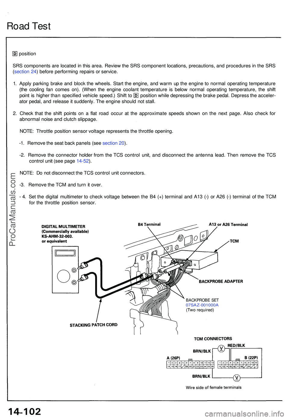
-3 . Remov e th e TC M an d tur n it over .
- 4 . Se t th e digita l multimete r t o chec k voltag e betwee n th e B 4 (+ ) termina l an d A1 3 (- ) o r A2 6 (- ) termina l o f th e TC M
fo r th e throttl e positio n sensor .
BACKPROB E SE T07SAZ-001000 A(Two required )
ProCarManuals.com
Page 779 of 1503
11. Remove the parking brake cable holders from the rear beam rod.
12. Remove the rear beam rod.
13. Remove the front exhaust pipe A.
14. Remove the parking brake cable holder and the wheel sensor wire clamp.
1 5. Make a reference mark on the flange of the adjusting bolt, adjusting cam and lower control arm.
16. Separate the toe control arm from the side beam.
17. Remove the damper fork bolt.
18. Separate the lower control arm from the side beam.
19. Remove the right driveshaft from the intermediate shaft.ProCarManuals.com
Page 780 of 1503
20. Remove the intermediate shaft heat shield cover and the intermediate shaft mounting bolts.
21. Pry the intermediate shaft out of the differential. Pull and remove it.
NOTE:
• Coat all precision finished surfaces with clean engine oil.
• Tie a plastic bag over the intermediate shaft end.
Removal (cont'd)
Transmission
22. Remove the parking brake cable holder and the wheel sensor wire clamp.
23. Make a reference mark on the flange of the adjusting bolt, adjusting cam and lower control arm.
24. Separate the toe control arm from the side beam.
25. Remove the damper fork bolt.
26. Separate the lower control arm from the side beam.
27. Pry the left driveshaft out of the differential. Pull and remove it.
NOTE:
• Coat all precision finished surfaces with clean engine oil.
• Tie a plastic bag over the driveshaft end.ProCarManuals.com
Page 836 of 1503
Installation (cont'd)
Transmission
11. Install a new set ring on the end of the left driveshaft and intermediate shaft. Apply a light film of grease around the
set ring grooves, then center the new set ring on the shafts. The grease keeps the set ring centered, making shaft
installation easier.
12. Install the left driveshaft.
13. Install the lower control arm to the side beam.
CAUTION: Line up the reference marks on the adjusting bolt, adjusting cam, and lower control arm.
14. Install the damper fork bolt.
15. Install the toe control arm to the side beam.
CAUTION: Make sure that the reference marks on the toe control arm are aligned.
16. Install the wheel sensor wire clamp and parking brake cable holder.
17. Install the intermediate shaft, and tighten the intermediate shaft mounting bolts to the intermediate shaft support
base.
18. Install the intermediate shaft heat shield cover.ProCarManuals.com
Page 837 of 1503
19. Install the right driveshaft on the intermediate shaft.
20. Install the lower control arm to the side beam.
CAUTION: Line up the reference marks on the adjusting bolt, adjusting cam, and lower control arm.
21. Install the damper fork bolt.
22. Install the toe control arm to the side beam.
CAUTION: Make sure that the reference marks on the toe control arm are aligned.
23. Install the wheel sensor wire clamp and parking brake cable holder.
24. Install the front exhaust pipe A.
25. Install the rear beam rod.
26. Install the parking brake cable.ProCarManuals.com
Page 877 of 1503

Driveshafts
Removal
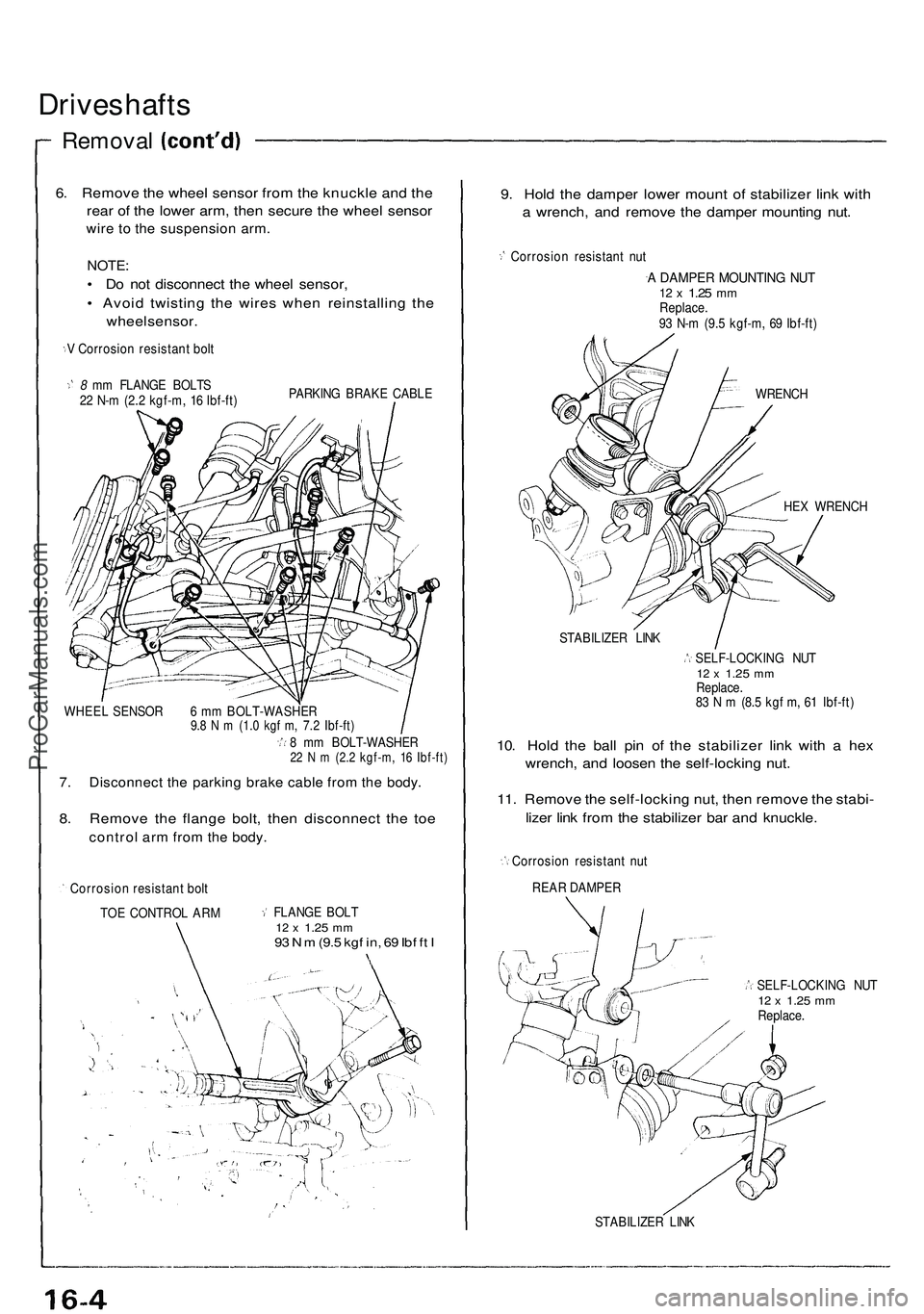
6. Remove the wheel sensor from the knuckle and the
rear of the lower arm, then secure the wheel sensor
wire to the suspension arm.
NOTE:
• Do not disconnect the wheel sensor,
• Avoid twisting the wires when reinstalling the
wheel sensor.
V Corrosion resistant bolt
8 mm FLANGE BOLTS
22 N-m (2.2 kgf-m, 16 Ibf-ft)
PARKING BRAKE CABLE
WHEEL SENSOR 6 mm BOLT-WASHER
9.8 N m (1.0 kgf m, 7.2 Ibf-ft)
8 mm BOLT-WASHER
22 N m (2.2 kgf-m, 16 Ibf-ft)
7. Disconnect the parking brake cable from the body.
8. Remove the flange bolt, then disconnect the toe
control arm from the body.
Corrosion resistant bolt
TOE CONTROL ARM
FLANGE BOLT
12 x
1.25
mm
93 N m
(9.5
kgf in, 69 Ibf ft I
9. Hold the damper lower mount of stabilizer link with
a wrench, and remove the damper mounting nut.
Corrosion resistant nut
A DAMPER MOUNTING NUT
12 x
1.25
mm
Replace.
93 N-m (9.5 kgf-m, 69 Ibf-ft)
WRENCH
HEX WRENCH
STABILIZER LINK
SELF-LOCKING NUT
12 x
1.25
mm
Replace.
83 N m (8.5 kgf m, 61 Ibf-ft)
10. Hold the ball pin of the stabilizer link with a hex
wrench, and loosen the self-locking nut.
11. Remove the self-locking nut, then remove the stabi-
lizer link from the stabilizer bar and knuckle.
Corrosion resistant nut
REAR DAMPER
SELF-LOCKING NUT
12 x
1.25
mm
Replace.
STABILIZER LINKProCarManuals.com