Page 280 of 1503
Security Alarm System
Control Unit Input Test
Remove the glove box, and disconnect the 22P connec-
tor and 16P connector from the control unit.
Inspect the connector and socket terminals to be sure
they are all making good contact.
• If the terminals are bent, loose, or corroded, repair
them as necessary, and recheck the system.
• If the terminals look OK, make the following input
tests at the connector.
If any test indicates a problem, find and correct the
cause, then recheck the system.
If all the input tests prove OK, the control unit
must be faulty; replace it.
• Different wires with the same color have been given a
number suffix to distinguish them (for example,
YEL/GRN1 and YEL/GRN2 are not the same).ProCarManuals.com
Page 290 of 1503

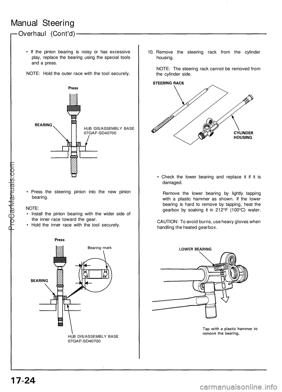
Overhaul (Cont'd )
Manual Steerin g
• I f th e pinio n bearin g i s nois y o r ha s excessiv e
play , replac e th e bearin g usin g th e specia l tool s
an d a press .
NOTE : Hol d th e oute r rac e wit h th e too l securely .10
. Remov e th e steerin g rac k fro m th e cylinde r
housing.
NOTE: Th e steerin g rac k canno t b e remove d fro m
th e cylinde r side .
HUB DIS/ASSEMBL Y BAS E07GAF-SD4070 0
• Chec k th e lowe r bearin g an d replac e i t i f i t i s
damaged .
Remov e th e lowe r bearin g b y lightl y tappin g
with a plasti c hamme r a s shown . I f th e lowe r
bearin g i s har d t o remov e b y tapping , hea t th e
gearbo x b y soakin g i t i n 212° F (100°C ) water .
CAUTION : T o avoi d burns , us e heav y glove s whe n
handlin g th e heate d gearbox .
•
Pres s th e steerin g pinio n int o th e ne w pinio n
bearing .
NOTE :
• Instal l th e pinio n bearin g wit h th e wide r sid e of
th e inne r rac e towar d th e gear .
• Hol d th e inne r rac e wit h th e too l securely .
HUB DIS/ASSEMBL Y BAS E07GAF-SD4070 0
ProCarManuals.com
Page 354 of 1503
Power Door Locks
Control Unit Input Test
1. Remove the glove box, then disconnect the 20P connector from the control unit.
2. Inspect the connector terminals to be sure they are all making good contact.
• If the terminals are bent, loose, or corroded, repair them as necessary, and recheck the system.
• If the terminals look OK, make the following input tests at the connector.
— If any test indicates a problem, find and correct the cause, then recheck the system.
— If all the input tests prove OK, the control unit must be faulty; replace it.ProCarManuals.com
Page 360 of 1503
Security Alarm System
Control Unit Input Test
Remove the glove box, and disconnect the 22P connec-
tor and 16P connector from the control unit.
Inspect the connector and socket terminals to be sure
they are all making good contact.
• If the terminals are bent, loose, or corroded, repair
them as necessary, and recheck the system.
• If the terminals look OK, make the following input
tests at the connector.
— If any test indicates a problem, find and correct the
cause, then recheck the system.
— If all the input tests prove OK, the control unit must
be faulty; replace it.
• Different wires with the same color have been given a
number suffix to distinguish them (for example,
YEL/GRN1 and YEL/GRN2 are not the same).ProCarManuals.com
Page 370 of 1503

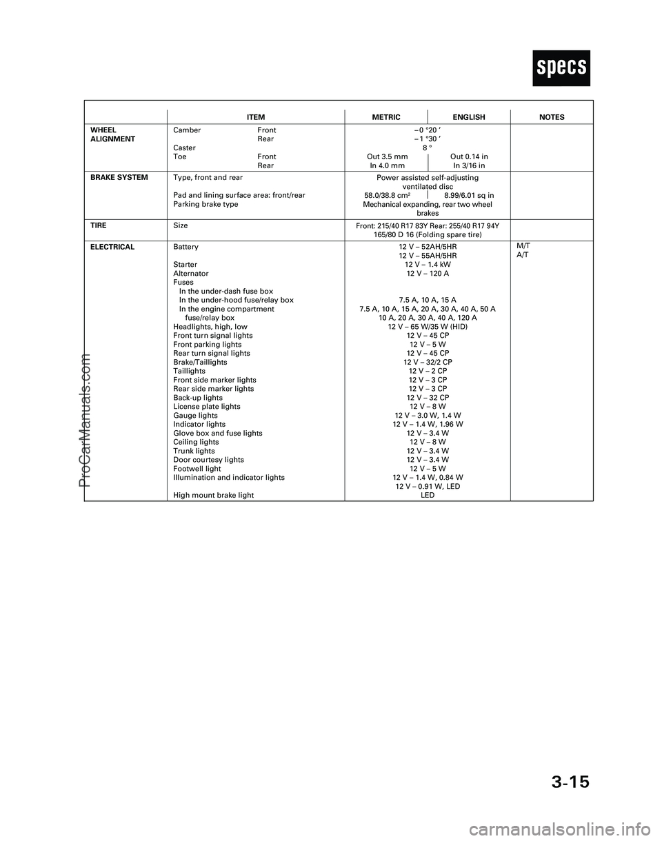
3-15
T
ITEMMETRICENGLISH
ELECTRICALBattery
Starter
Alternator
Fuses
In the under-dash fuse box
In the under-hood fuse/relay box
In the engine compartment
fuse/relay box
Headlights, high, low
Front turn signal lights
Front parking lights
Rear turn signal lights
Brake/Taillights
Taillights
Front side marker lights
Rear side marker lights
Back-up lights
License plate lights
Gauge lights
Indicator lights
Glove box and fuse lights
Ceiling lights
Trunk lights
Door courtesy lights
Footwell light
Illumination and indicator lights
High mount brake light12 V – 52AH/5HR
12 V – 55AH/5HR
12 V – 1.4 kW
12 V – 120 A
7.5 A, 10 A, 15 A
7.5 A, 10 A, 15 A, 20 A, 30 A, 40 A, 50 A
10 A, 20 A, 30 A, 40 A, 120 A
12 V – 65 W/35 W (HID)
12 V – 45 CP
12 V – 5 W
12 V – 45 CP
12 V – 32/2 CP
12 V – 2 CP
12 V – 3 CP
12 V – 3 CP
12 V – 32 CP
12 V – 8 W
12 V – 3.0 W, 1.4 W
12 V – 1.4 W, 1.96 W
12 V – 3.4 W
12 V – 8 W
12 V – 3.4 W
12 V – 3.4 W
12 V – 5 W
12 V – 1.4 W, 0.84 W
12 V – 0.91 W, LED
LED
TIRE
M/T
A/T
BRAKE SYSTEM
Front: 215/40 R17 83Y Rear: 255/40 R17 94Y165/80 D 16 (Folding spare tire)
Power assisted self-adjusting
ventilated disc
58.0/38.8 cm
28.99/6.01 sq in
Mechanical expanding, rear two wheel
brakes
WHEEL
ALIGNMENTCamber Front
Rear
Caster
Toe Front
Rear–0 °20 ’
–1 °30 ’
8 °
Out 3.5 mm Out 0.14 in
In 4.0 mm In 3/16 in
NOTES
Size
Type, front and rear
Pad and lining surface area: front/rear
Parking brake type
*04-NSX (61SW004)SEC03(01-16) 9/22/04 1:49 PM Page 3-15
ProCarManuals.com
Page 1112 of 1503
Climate control unit, stereo cassette/radio and glove box removal:
Disassemble in numbered sequence.
NOTE: Remove the center console panel.
CLIMATE CONTROL
UNIT
Disconnect the connectors.
SRS UNIT
Passenger's:
STEREO
CASSETTE RADIO
Disconnect the connectors.
GROUND CABLE
GLOVE BOX
Disconnect the connectors.
TRUNK LID OPENER
MAIN SWITCH
PASSENGER'S
AIRBAG
DLC
CONNECTOR
GLOVE BOX
LID
DASHBOARD LOWER
COVER (Passenger's)
Installation is the reverse of the removal procedure.
NOTE: Make sure the connectors are connected properly.
(cont'd)ProCarManuals.com
Page 1353 of 1503
Glove Box Light
Replacement/Test
1. Remove the glove box lower panel.
GLOVE
BOX
GLOVE BOX LOWER
PANEL
2. Remove the eight screws, then pull out the glove
box.
3. Disconnect the 2P connectors, then remove the glove
box.
4. Remove the two screws from the glove box light.
BULB
(3.4
W)
5. Check for continuity between the A terminal and B
terminal with a bulb installed. There should be con-
tinuity. There should be no continuity when the
switch plunger is pushed.
GLOVE BOX
LID
From
No.38 (15A1FUSE
G401
G402
G403
GLOVE BOX LIGHTProCarManuals.com
Page 1399 of 1503
Main Switch Test
1. Remove the glove box, and disconnect the 2P con-
nector from the switch.
2. Check for continuity between the terminals.
There should be continuity between the No. 1
terminal and No. 2 terminal with the main
switch ON.
There should be no continuity with the main
switch OFF.
View from
wire side
MAIN SWITCH
3. If necessary, replace the switch.
MAIN SWITCHProCarManuals.com