Page 163 of 1202

SS0LP-06
- SERVICE SPECIFICATIONSSUSPENSION AND AXLE
SS-33
1996 TERCEL (RM440U)
TORQUE SPECIFICATION
Part tightenedN´mkgf´cmft´lbf
FRONT:
Disc brake dust cover x Steering knuckle8.38574 in.´lbf
Lower ball joint x Steering knuckle981,00072
Steering knuckle x Shock absorber2452,500181
Lower ball joint x Lower suspension arm8082059
Tie rod end lock nut4748035
Tie rod end x Steering knuckle4950036
Disc brake caliper x Steering knuckle8890065
Drive shaft lock nut2162,200159
Piston rod x Suspension support4747534
Suspension support x Body3940029
Flexible hose x Shock absorber2930022
Lower suspension arm x BodyFront side1421,450105Lower sus ension arm x Body Front side
Rear side
142
74
1,450
750
105
55
Hub nut1031,05076
ABS speed sensor x Steering knuckle7.88069 in.´lbf
REAR:
Piston rod x Suspension support3435025
Suspension support x Body3940029
Shock absorber x Axle beam6869050
Backing plate x Axle beam7071051
Parking brake cable x Backing plate7.88069 in.´lbf
Brake line x Wheel cylinder1515511
Body x Axle beam1421,450105
Lateral control rod x Axle beam8385061
Lateral control rod x Body11 31,15083
ABS speed sensor x Axle beam7.88069 in.´lbf
ABS speed sensor wire x Axle beam5.45548 in.´lbf
Page 165 of 1202
SS0M3-10
- SERVICE SPECIFICATIONSBRAKE
SS-35
1996 TERCEL (RM440U)
TORQUE SPECIFICATION
Part tightenedN´mkgf´cmft´lbf
Master cylinder x Piston stopper bolt101007
Master cylinder x Reservoir1.717.515.2 in.´lbf
Master cylinder x Brake booster131309
Brake line union nut1515511
Brake booster clevis lock nut2526019
Brake booster x Pedal bracket1414510
Front disc brake caliper installation bolt2525518
Bleeding plug8.38574 in.´lbf
Front disc brake torque plate x Steering knuckle8890065
Front disc brake caliper x Flexible hose3031022
Rear drum brake wheel cylinder x Backing plate101007
ABS actuator assembly x Body1919514
ABS actuator x ABS actuator bracket assembly5.45548 in.´lbf
ABS actuator x ABS actuator No. 3 bracket1919514
Front speed sensor x Steering knuckle8.08271 in.´lbf
Front speed sensor wire harness clamp installation bolt5.05144 in.´lbf
Rear speed sensor x Axle beam8.08271 in.´lbf
Rear speed sensor wire harness clamp installation bolt5.05144 in.´lbf
Page 166 of 1202
SS0N1-03
SS-36
- SERVICE SPECIFICATIONSSTEERING
166 Author�: Date�:
1996 TERCEL (RM440U)
STEERING
SERVICE DATA
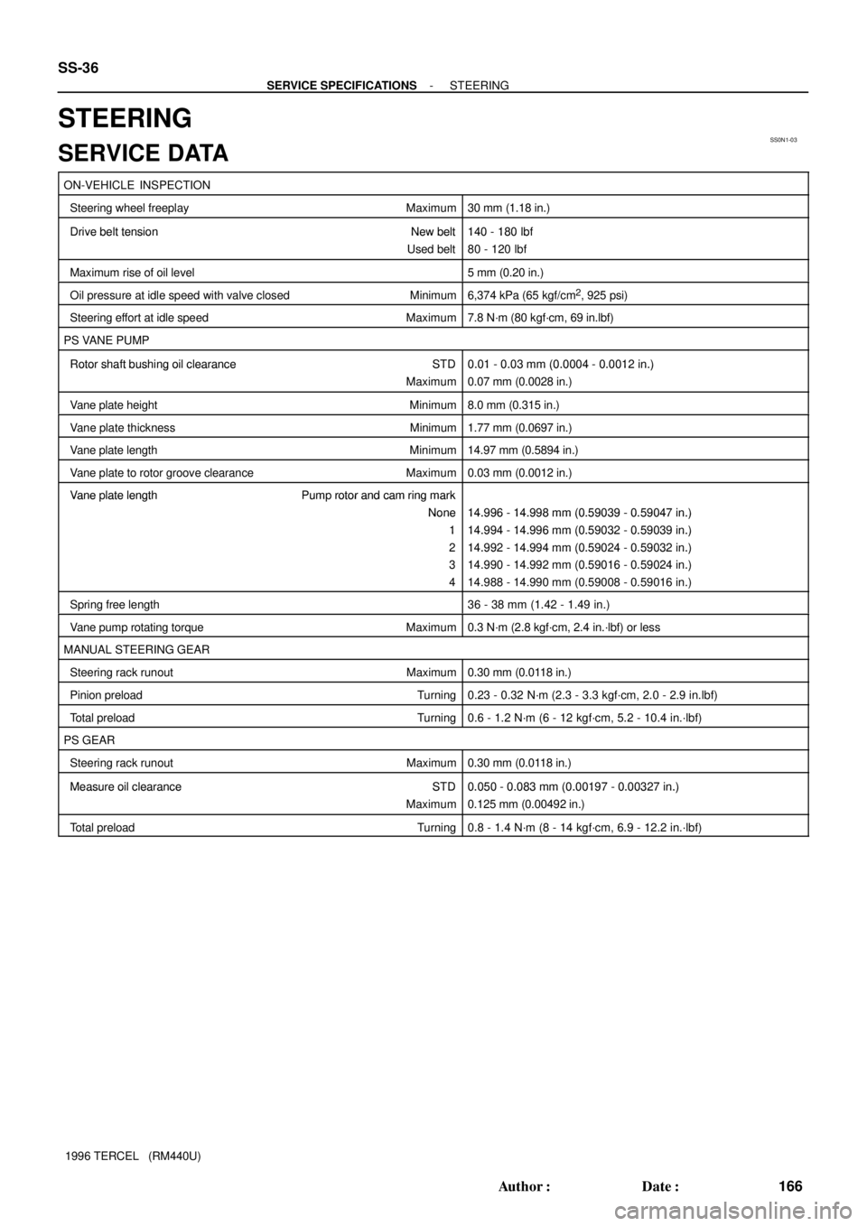
ON-VEHICLE INSPECTION
Steering wheel freeplayMaximum30 mm (1.18 in.)
Drive belt tension New belt140 - 180 lbf Drive belt tension New belt
Used belt
140 180 lbf
80 - 120 lbf
Maximum rise of oil level5 mm (0.20 in.)
Oil pressure at idle speed with valve closed Minimum6,374 kPa (65 kgf/cm2, 925 psi)
Steering effort at idle speedMaximum7.8 N´m (80 kgf´cm, 69 in.lbf)
PS VANE PUMP
Rotor shaft bushing oil clearance STD0.01 - 0.03 mm (0.0004 - 0.0012 in.) Rotor shaft bushing oil clearance STD
Maximum
0.01 0.03 mm (0.0004 0.0012 in.)
0.07 mm (0.0028 in.)
Vane plate heightMinimum8.0 mm (0.315 in.)
Vane plate thickness Minimum1.77 mm (0.0697 in.)
Vane plate lengthMinimum14.97 mm (0.5894 in.)
Vane plate to rotor groove clearanceMaximum0.03 mm (0.0012 in.)
Vane plate length Pump rotor and cam ring mark Vane late length Pum rotor and cam ring mark
None14.996 - 14.998 mm (0.59039 - 0.59047 in.)None
1
14.996 - 14.998 mm (0.59039 - 0.59047 in.)
14.994 - 14.996 mm (0.59032 - 0.59039 in.)1
2
14.994 14.996 mm (0.59032 0.59039 in.)
14.992 - 14.994 mm (0.59024 - 0.59032 in.)2
3
14.992 14.994 mm (0.59024 0.59032 in.)
14.990 - 14.992 mm (0.59016 - 0.59024 in.)3
4
14.990 14.992 mm (0.59016 0.59024 in.)
14.988 - 14.990 mm (0.59008 - 0.59016 in.)
Spring free length36 - 38 mm (1.42 - 1.49 in.)
Vane pump rotating torqueMaximum0.3 N´m (2.8 kgf´cm, 2.4 in.´lbf) or less
MANUAL STEERING GEAR
Steering rack runout Maximum0.30 mm (0.0118 in.)
Pinion preload Turning0.23 - 0.32 N´m (2.3 - 3.3 kgf´cm, 2.0 - 2.9 in.lbf)
Total preload Turning0.6 - 1.2 N´m (6 - 12 kgf´cm, 5.2 - 10.4 in.´lbf)
PS GEAR
Steering rack runout Maximum0.30 mm (0.0118 in.)
Measure oil clearance STD0.050 - 0.083 mm (0.00197 - 0.00327 in.) Measure oil clearance STD
Maximum
0.050 0.083 mm (0.00197 0.00327 in.)
0.125 mm (0.00492 in.)
Total preload Turning0.8 - 1.4 N´m (8 - 14 kgf´cm, 6.9 - 12.2 in.´lbf)
Page 167 of 1202
SS0N2-05
- SERVICE SPECIFICATIONSSTEERING
SS-37
1996 TERCEL (RM440U)
TORQUE SPECIFICATION
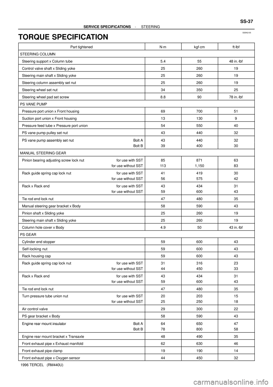
Part tightenedN´mkgf´cmft´lbf
STEERING COLUMN
Steering support x Column tube5.45548 in.´lbf
Control valve shaft x Sliding yoke2526019
Steering main shaft x Sliding yoke2526019
Steering column assembly set nut2526019
Steering wheel set nut3435025
Steering wheel pad set screw8.89078 in.´lbf
PS VANE PUMP
Pressure port union x Front housing6970051
Suction port union x Front housing131309
Pressure feed tube x Pressure port union5455040
PS vane pump pulley set nut4344032
PS vane pump assembly set nut Bolt A4344032 PS vane um assembly set nut Bolt A
Bolt B
43
39
440
400
32
30
MANUAL STEERING GEAR
Pinion bearing adjusting screw lock nut for use with SST
for use without SST85
11 3871
1,15063
83
Rack guide spring cap lock nut for use with SST
for use without SST41
56419
57530
42
Rack x Rack end for use with SST
for use without SST43
59434
60031
43
Tie rod end lock nut4748035
Manual steering gear bracket x Body5859043
Pinion shaft x Sliding yoke2526019
Steering main shaft x Sliding yoke2526019
Column hole cover x Body4.95043 in.´lbf
PS GEAR
Cylinder end stopper5960043
Self-locking nut5960043
Rack housing cap5960043
Rack guide spring cap lock nut for use with SST
for use without SST31
44316
45023
33
Rack x Rack end for use with SST
for use without SST43
59434
60031
43
Tie rod end lock nut4748035
Turn pressure tube union nut for use with SST
for use without SST20
25203
25015
18
Air control valve2930022
PS gear bracket x Body5859043
Engine rear mount insulator Bolt A6465047 Engine rear mount insulator Bolt A
Bolt B
64
78
650
800
47
58
Engine rear mount bracket x Transaxle4849035
Front exhaust pipe x Exhaust manifold6263046
Front exhaust pipe clamp1919014
Front exhaust pipe x Oxygen sensor4445032
Page 169 of 1202
SS061-41
- SERVICE SPECIFICATIONSSUPPLEMENTAL RESTRAINT SYSTEM
SS-39
169 Author�: Date�:
1996 TERCEL (RM440U)
SUPPLEMENTAL RESTRAINT SYSTEM
TORQUE SPECIFICATION
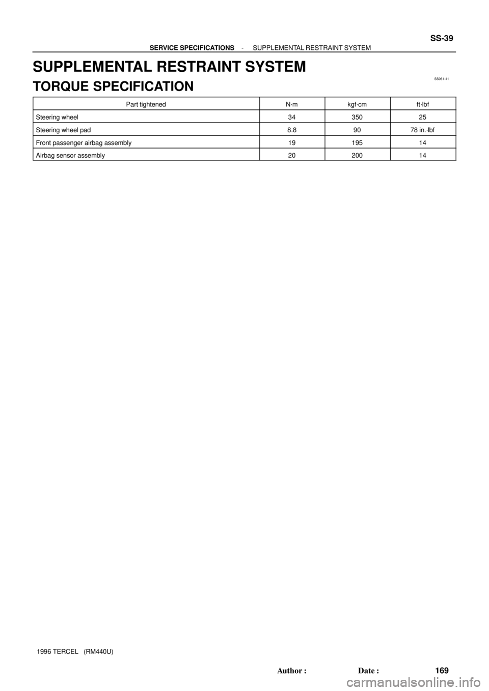
Part tightenedN´mkgf´cmft´lbf
Steering wheel3435025
Steering wheel pad8.89078 in.´lbf
Front passenger airbag assembly1919514
Airbag sensor assembly2020014
Page 172 of 1202
SS0NJ-06
SS-42
- SERVICE SPECIFICATIONSBODY
172 Author�: Date�:
1996 TERCEL (RM440U)
BODY
TORQUE SPECIFICATION
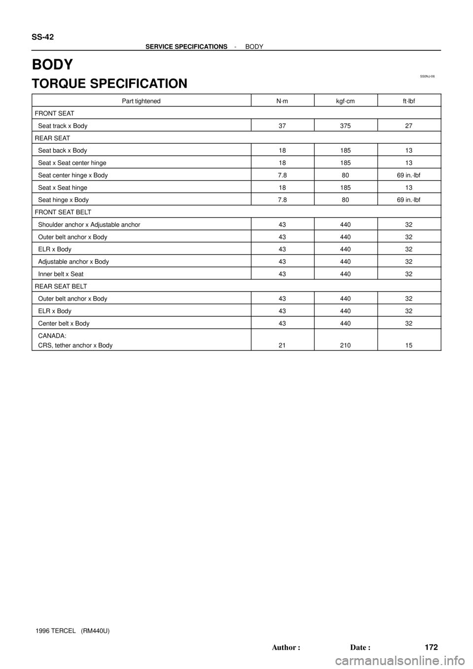
Part tightenedN´mkgf´cmft´lbf
FRONT SEAT
Seat track x Body3737527
REAR SEAT
Seat back x Body1818513
Seat x Seat center hinge1818513
Seat center hinge x Body7.88069 in.´lbf
Seat x Seat hinge1818513
Seat hinge x Body7.88069 in.´lbf
FRONT SEAT BELT
Shoulder anchor x Adjustable anchor4344032
Outer belt anchor x Body4344032
ELR x Body4344032
Adjustable anchor x Body4344032
Inner belt x Seat4344032
REAR SEAT BELT
Outer belt anchor x Body4344032
ELR x Body4344032
Center belt x Body4344032
CANADA:
CRS, tether anchor x Body
2121015
Page 174 of 1202
SS0MA-05
SS-44
- SERVICE SPECIFICATIONSAIR CONDITIONING
1996 TERCEL (RM440U)
TORQUE SPECIFICATION
Part tightenedN´mkgf´cmft´lbf
Compressor x Suction hose101007
Compressor x Discharge hose101007
Compressor x Compressor bracket2525018
Receiver x Liquid tube5.45548 in.´lbf
Condenser x Liquid tube5.45548 in.´lbf
Cooling unit x Liquid tube1414010
Cooling unit x Suction tube3233024
Expansion valve x Evaporator5.45548 in.´lbf
Revolution detecting sensor x Compressor1111 08
Pressure plate x Compressor1414010
Page 428 of 1202
EM0494
P20156
SST(A)
SST(B)
EM-6
- ENGINE MECHANICALVALVE CLEARANCE
427 Author�: Date�:
1996 TERCEL (RM440U)
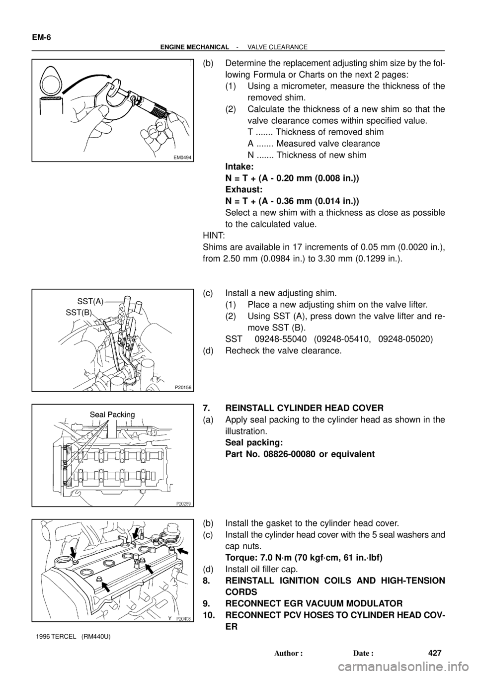
(b) Determine the replacement adjusting shim size by the fol-
lowing Formula or Charts on the next 2 pages:
(1) Using a micrometer, measure the thickness of the
removed shim.
(2) Calculate the thickness of a new shim so that the
valve clearance comes within specified value.
T ....... Thickness of removed shim
A ....... Measured valve clearance
N ....... Thickness of new shim
Intake:
N = T + (A - 0.20 mm (0.008 in.))
Exhaust:
N = T + (A - 0.36 mm (0.014 in.))
Select a new shim with a thickness as close as possible
to the calculated value.
HINT:
Shims are available in 17 increments of 0.05 mm (0.0020 in.),
from 2.50 mm (0.0984 in.) to 3.30 mm (0.1299 in.).
(c) Install a new adjusting shim.
(1) Place a new adjusting shim on the valve lifter.
(2) Using SST (A), press down the valve lifter and re-
move SST (B).
SST 09248-55040 (09248-05410, 09248-05020)
(d) Recheck the valve clearance.
7. REINSTALL CYLINDER HEAD COVER
(a) Apply seal packing to the cylinder head as shown in the
illustration.
Seal packing:
Part No. 08826-00080 or equivalent
(b) Install the gasket to the cylinder head cover.
(c) Install the cylinder head cover with the 5 seal washers and
cap nuts.
Torque: 7.0 N´m (70 kgf´cm, 61 in.´lbf)
(d) Install oil filler cap.
8. REINSTALL IGNITION COILS AND HIGH-TENSION
CORDS
9. RECONNECT EGR VACUUM MODULATOR
10. RECONNECT PCV HOSES TO CYLINDER HEAD COV-
ER