Page 930 of 1202

6. INSTALL VANE PLATES
Install the 10 plates with the round end facing outward.
7. INSTALL SIDE REAR PLAT")
R11071
Round End
R12361
R12362
- STEERINGPOWER STEERING VANE PUMP
SR-31
1996 TERCEL (RM440U)
6. INSTALL VANE PLATES
Install the 10 plates with the round end facing outward.
7. INSTALL SIDE REAR PLATe
(a) Coat a new O-ring with power steering fluid, and install
it to the plate.
(b) Align the holes of the plate and straight pins.
8. INSTALL WAVE WASHER
Install the washer so that its protrusions fit into the slots in the
side rear plate.
9. INSTALL REAR HOUSING
(a) Coat a new O-ring with power steering fluid and install it
to the rear housing.
(b) Install the rear housing and use a press to push down on
the wave washer hard enough to compress it.
NOTICE:
�Do not apply too much pressure.
�Be careful not to damage the O-ring.
10. INSTALL SPRING, FLOW CONTROL VALVE AND
PRESSURE PORT UNION
(a) Install the valve facing the correct direction.
(See page SR-22)
(b) Coat a new O-ring with power steering fluid, and install
it to the union.
(c) Torque the union.
Torque: 69 N´m (700 kgf´cm, 51 ft´lbf)
11. INSTALL SUCTION PORT UNION
(a) Coat a new O-ring with power steering fluid, and install
it to the union.
(b) Torque the 2 bolts.
Torque: 13 N´m (130 kgf´cm, 9 ft´lbf)
Page 931 of 1202
SR-32
- STEERINGPOWER STEERING VANE PUMP
1996 TERCEL (RM440U)
12. INSTALL VANE PUMP PULLEY
(a) Install the woodruff key to the vane pump shaft.
(b) Using SST to stop the pulley rotating, torque the pulley set
nut.
SST 09960-10010 (09962-01000, 09963-01000)
Torque: 43 N´m (440 kgf´cm, 32 ft´lbf)
13. MEASURE PS VANE PUMP ROTATING TORQUE
(See page SR-25)
Page 932 of 1202
SR0KQ-03
- STEERINGPOWER STEERING VANE PUMP
SR-33
1996 TERCEL (RM440U)
INSTALLATION
1. INSTALL PS VANE PUMP ASSEMBLY
Temporarily tighten the 2 bolts (A and B).
2. INSTALL DRIVE BELT
(a) Adjust drive belt tension (See page SR-3).
(b) Torque the A bolt.
Torque: 43 N´m (440 kgf´cm, 32 ft´lbf)
(c) Torque the B bolt.
Torque: 39 N´m (400 kgf´cm, 30 ft´lbf)
3. CONNECT PRESSURE FEED TUBE
Torque the union bolt over a new gasket.
Torque: 54 N´m (550 kgf´cm, 40 ft´lbf)
4. CONNECT RETURN HOSE
5. BLEED POWER STEERING SYSTEM
(See page SR-5)
Page 945 of 1202
SR0KX-04
SR-46
- STEERINGPOWER STEERING GEAR
966 Author�: Date�:
1996 TERCEL (RM440U)
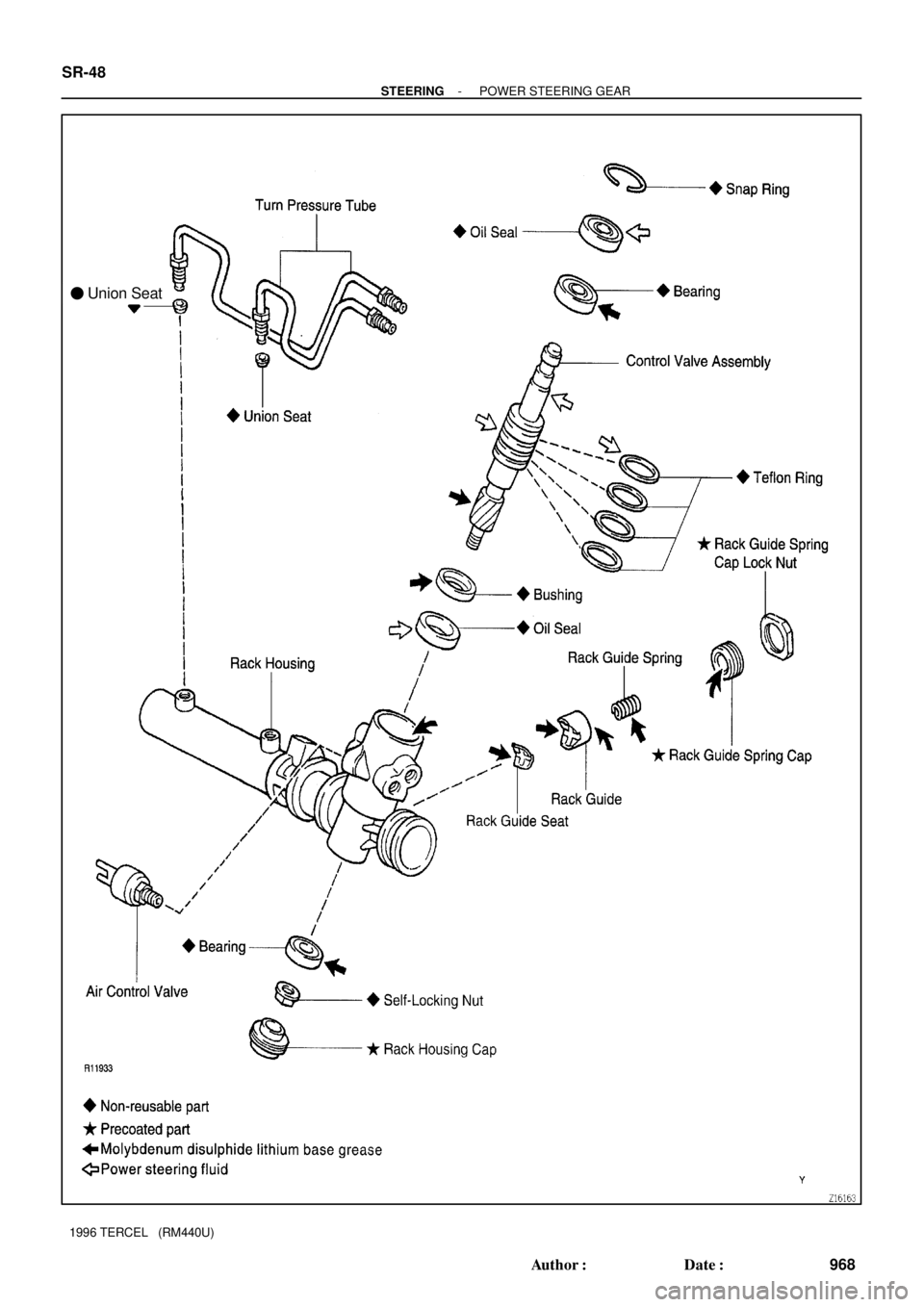
POWER STEERING GEAR
COMPONENTS
Page 946 of 1202
- STEERINGPOWER STEERING GEAR
SR-47
967 Author�: Date�:
1996 TERCEL (RM440U)
Page 947 of 1202
� Union Seat SR-48
- STEERINGPOWER STEERING GEAR
968 Author�: Date�:
1996 TERCEL (RM440U)
Page 948 of 1202

REMOVAL
1. PLACE FRONT WHEELS FACING STRAIGHT AHEAD
2. w/ Airbag:
REMOVE STEERING WHEEL PAD (See page SR-13)
3. w/")
SR0KY-02
R11074
SST
SR4244
- STEERINGPOWER STEERING GEAR
SR-49
1996 TERCEL (RM440U)
REMOVAL
1. PLACE FRONT WHEELS FACING STRAIGHT AHEAD
2. w/ Airbag:
REMOVE STEERING WHEEL PAD (See page SR-13)
3. w/ Airbag:
REMOVE STEERING WHEEL (See page SR-13)
4. DISCONNECT RH AND LH TIE ROD ENDS (See page
SA-10)
5. REMOVE COLUMN HOLE COVER
Remove the 2 bolts and nut.
6. DISCONNECT SLIDING YOKE (See page SR-13)
7. REMOVE OXYGEN SENSOR
8. REMOVE FRONT EXHAUST PIPE
(a) Remove the 2 bolts, compression springs and gasket.
(b) Remove the bolt, clamp and gasket.
(c) Disconnect the 2 rings.
9. REMOVE ENGINE REAR MOUNT INSULATOR
Remove the 6 bolts.
10. REMOVE ENGINE REAR MOUNT BRACKET
Remove the 2 bolts.
11. DISCONNECT 2 VACUUM HOSES
12. M/T:
DISCONNECT CONTROL CABLES
(a) Remove the 2 clips and washers.
(b) Remove the 2 clips from the cables.
(c) Disconnect the 2 cables from the control lever housing
support bracket.
13. DISCONNECT PRESSURE FEED AND RETURN
TUBES
Using SST, disconnect the tube.
SST 09631-22020
14. DISCONNECT TUBE CLAMP
Remove the bolt.
15. REMOVE 2 BRACKETS AND GROMMETS
Remove the 2 bolts and nuts.
16. REMOVE PS GEAR ASSEMBLY
(a) Slide the gear assembly to the RH side of the vehicle.
(b) Slide the gear assembly to the LH side and pull it out.
Page 949 of 1202

DISASSEMBLY
NOTICE:
When using a vise, do not overtighten it.
1. SECURE PS GEAR ASSEMBLY IN")
SR17W-02
R11026
SST
R11027
SST
R13122
R11029
SST SR-50
- STEERINGPOWER STEERING GEAR
1996 TERCEL (RM440U)
DISASSEMBLY
NOTICE:
When using a vise, do not overtighten it.
1. SECURE PS GEAR ASSEMBLY IN VISE
Using SST, secure the gear assembly in a vise.
SST 09612-00012
2. REMOVE 2 TURN PRESSURE TUBES
(a) Using SST, remove the tube.
SST 09633-00020
(b) Remove the 2 union seats from the rack housing.
3. REMOVE AIR CONTROL VALVE
4. REMOVE RH AND LH TIE ROD ENDS AND LOCK
NUTS (See page SR-37)
5. REMOVE RH AND LH CLIPS, RACK BOOTS AND
CLAMPS
Using a screwdriver, loosen the clamp.
NOTICE:
�Be careful not to damage the boot.
�Mark the RH and LH boots.
6. REMOVE RH AND LH RACK ENDS AND CLAW WASH-
ERS (See page SR-37)
7. REMOVE RACK GUIDE SPRING CAP LOCK NUT
Using SST, remove the nut.
SST 09922-10010
NOTICE:
Use SST 09922-10010 in the direction shown in the illustra-
tion.
8. REMOVE RACK GUIDE SPRING CAP
Using a hexagon wrench (21 mm), remove the cap.
9. REMOVE RACK GUIDE SPRING, RACK GUIDE AND
RACK GUIDE SEAT
Remove the seat from the guide.
10. REMOVE RACK HOUSING CAP

12. INSTALL VANE PUMP PULLEY
(a) Install the woodruff key to the vane pump shaft.
(b) Using SST to stop the pulley rotating, torque the")

INSTALLATION
1. INSTALL PS VANE PUMP ASSEMBLY
Temporarily tighten the 2 bolts (A and B).
2. INSTALL DRIVE BELT
(a) Adjust drive")