Page 446 of 1202

EG0023
EM-24
- ENGINE MECHANICALCYLINDER HEAD
1996 TERCEL (RM440U)
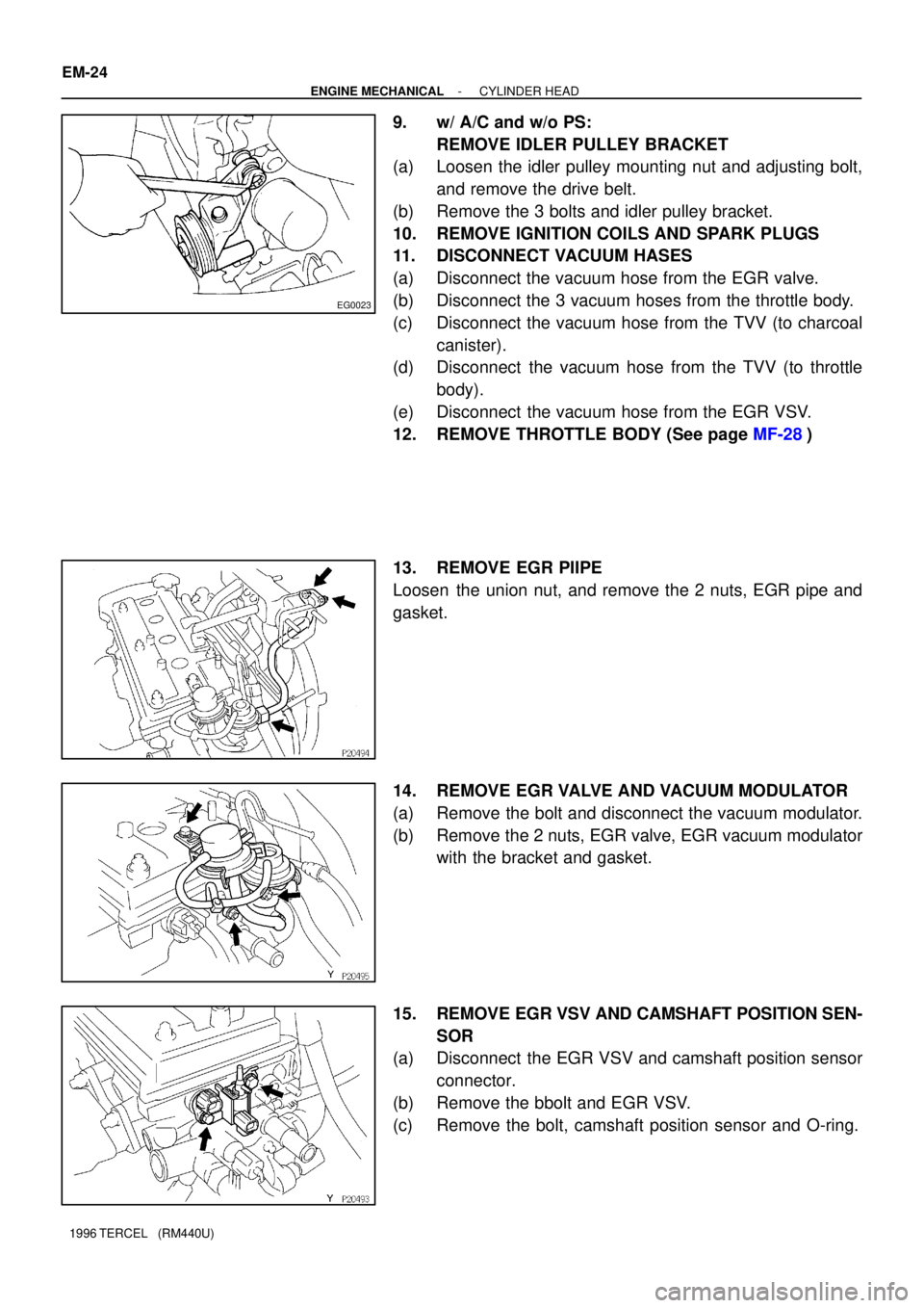
9. w/ A/C and w/o PS:
REMOVE IDLER PULLEY BRACKET
(a) Loosen the idler pulley mounting nut and adjusting bolt,
and remove the drive belt.
(b) Remove the 3 bolts and idler pulley bracket.
10. REMOVE IGNITION COILS AND SPARK PLUGS
11. DISCONNECT VACUUM HASES
(a) Disconnect the vacuum hose from the EGR valve.
(b) Disconnect the 3 vacuum hoses from the throttle body.
(c) Disconnect the vacuum hose from the TVV (to charcoal
canister).
(d) Disconnect the vacuum hose from the TVV (to throttle
body).
(e) Disconnect the vacuum hose from the EGR VSV.
12. REMOVE THROTTLE BODY (See page MF-28)
13. REMOVE EGR PIIPE
Loosen the union nut, and remove the 2 nuts, EGR pipe and
gasket.
14. REMOVE EGR VALVE AND VACUUM MODULATOR
(a) Remove the bolt and disconnect the vacuum modulator.
(b) Remove the 2 nuts, EGR valve, EGR vacuum modulator
with the bracket and gasket.
15. REMOVE EGR VSV AND CAMSHAFT POSITION SEN-
SOR
(a) Disconnect the EGR VSV and camshaft position sensor
connector.
(b) Remove the bbolt and EGR VSV.
(c) Remove the bolt, camshaft position sensor and O-ring.
Page 475 of 1202

EG0023
P20290
- ENGINE MECHANICALCYLINDER HEAD
EM-53
1996 TERCEL (RM440U)
22. INSTALL EGR PIPE
Install a new gasket, sleeve ball and the EGR pipe with the
union nut and 2 nuts.
Torque:
Union nut
40 N´m (400 kgf´cm, 29 in.´lbf)
Nut
30 N´m (300 kgf´cm, 22 in.´lbf)
23. INSTALL THROTTLE BODY (See page MF-32)
24. CONNECT VACUUM HOSES
(a) Connect the vacuum hose from the EGR valve.
(b) Connect the 3 vacuum hoses from the throttle body.
(c) Connect the vacuum hose from TVV (to charcoal canis-
ter).
(d) Connect the vacuum hose from the TVV (to throttle body).
(e) Connect the vacuum hose from the EGR VSV.
25. INSTALL IGNITION COILS AND SPARK PLUGS
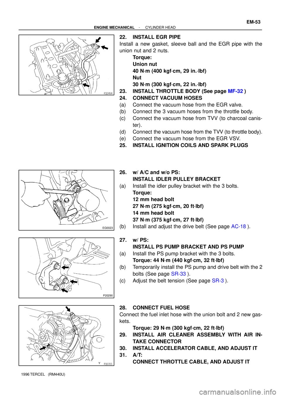
26. w/ A/C and w/o PS:
INSTALL IDLER PULLEY BRACKET
(a) Install the idler pulley bracket with the 3 bolts.
Torque:
12 mm head bolt
27 N´m (275 kgf´cm, 20 ft´lbf)
14 mm head bolt
37 N´m (375 kgf´cm, 27 ft´lbf)
(b) Install and adjust the drive belt (See page AC-18).
27. w/ PS:
INSTALL PS PUMP BRACKET AND PS PUMP
(a) Install the PS pump bracket with the 3 bolts.
Torque: 44 N´m (440 kgf´cm, 32 ft´lbf)
(b) Temporarily install the PS pump and drive belt with the 2
bolts (See page SR-33).
(c) Adjust the belt tension (See page SR-3).
28. CONNECT FUEL HOSE
Connect the fuel inlet hose with the union bolt and 2 new gas-
kets.
Torque: 29 N´m (300 kgf´cm, 22 ft´lbf)
29. INSTALL AIR CLEANER ASSEMBLY WITH AIR IN-
TAKE CONNECTOR
30. INSTALL ACCELERATOR CABLE, AND ADJUST IT
31. A/T:
CONNECT THROTTLE CABLE, AND ADJUST IT
Page 520 of 1202

Port B
Port C
(a)
(b)
P05838
EC-6
- EMISSION CONTROLEVAPORATIVE EMISSION (EVAP) CONTROL SYSTEM
519 Author�: Date�:
1996 TERCEL (RM440U)
(c) Clean the filter by blowing 294 kPa (3 kgf/cm2,
43 psi) of
compressed air into port A while holding port B closed.
NOTICE:
�Do not attempt to wash the canister.
�No activated carbon shold come out.
8. REINSTALL CAP TO CHARCOAL CANISTER
9. REINSTALL CHARCOAL CANISTER
10. DRAIN ENGINE COOLANT
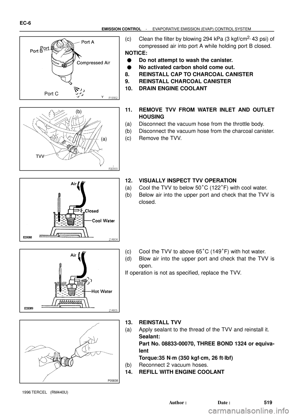
11. REMOVE TVV FROM WATER INLET AND OUTLET
HOUSING
(a) Disconnect the vacuum hose from the throttle body.
(b) Disconnect the vacuum hose from the charcoal canister.
(c) Remove the TVV.
12. VISUALLY INSPECT TVV OPERATION
(a) Cool the TVV to below 50°C (122°F) with cool water.
(b) Below air into the upper port and check that the TVV is
closed.
(c) Cool the TVV to above 65°C (149°F) with hot water.
(d) Blow air into the upper port and check that the TVV is
open.
If operation is not as specified, replace the TVV.
13. REINSTALL TVV
(a) Apply sealant to the thread of the TVV and reinstall it.
Sealant:
Part No. 08833-00070, THREE BOND 1324 or equiva-
lent
Torque:35 N´m (350 kgf´cm, 26 ft´lbf)
(b) Reconnect 2 vacuum hoses.
14. REFILL WITH ENGINE COOLANT
Page 526 of 1202

SF1PQ-02
- MFIMFI SYSTEM
MF-1
525 Author�: Date�:
1996 TERCEL (RM440U)
MFI SYSTEM
PRECAUTION
1. BEFORE WORKING ON FUEL SYSTEM, DISCON-
NECT NEGATIVE (-) TERMINAL CABLE FROM BAT-
TERY
HINT:
Any diagnostic trouble code retained by the computer will be
erased when the negative (-) terminal cable is disconnected.
Therefore, if necessary, read the diagnosis before disconnect-
ing the negative (-) terminal cable from the battery.
2. DO NOT SMOKE OR WORK NEAR AN OPEN FLAME
WHEN WORKING ON THE FUEL SYSTEM
3. KEEP GASOLINE AWAY FROM RUBBER OR LEATH-
ER PARTS
4. MAINTENANCE PRECAUTIONS
(a) In event of engine misfire, the following precautions
should be taken.
(1) Check proper connection to battery terminals, etc.
(2) Handle higt-tension cords carefully.
(3) After repair work, check that the ignition coil termi-
nals and all other ignition system lines are recon-
nected securely.
(4) When cleaning the engine compartment, be espe-
cially careful to protect the electrical system from
water.
(b) Precautions when handling the oxygen sensor.
(1) Do not allow the oxygen sensor to drop or hit
against an object.
(2) Do not allow the sensor to come into contact with
water.
5. IF VEHICLE IS EQUIPPED WITH MOBILE RADIO SYS-
TEM (HAM, CB, ETC.)
If the vehicle is equipped with a mobile communication system,
refer to the precaution in the IN section.
6. AIR INDUCTION SYSTEM
(a) Separation of the engine oil dipstick, oil filler cap, PCV
hose, etc. may cause the engine out of tune.
(b) Disconnection, looseness or cracks in the parts of the air
induction system between the throttle body and cylinder
head will cause air suction and cause the engine out of
tune.
7. ELECTRONIC CONTROL SYSTEM
(a) Before removing MFI wiring connectors, terminals, etc.,
first disconnect the power by either turning the ignition
switch to LOCK or disconnecting the negative (-) terminal
cable from the battery.
Page 551 of 1202
SF1PW-01
MF-26
- MFITHROTTLE BODY
550 Author�: Date�:
1996 TERCEL (RM440U)
THROTTLE BODY
ON-VEHICLE INSPECTION
1. INSPECT THROTTLE BODY
(a) Check that the throttle linkage moves smoothly.
(b) Check the vacuum at port.
(1) Start the engine.
(2) Check the vacuum with your finger.
Port nameAt idleOther than idle
PNo vacuumVacuum
ENo vacuumVacuum
RNo vacuumNo vacuum
2. INSPECT THROTTLE POSITION SENSOR
(a) A/T:
Disconnect the throttle cable from the linkage.
(b) Disconnect the sensor connector.
(c) Insert feeler gauge between the throttle stop screw and
stop lever.
(d) Using an ohmmeter, measure the resistance between
each terminal.
Clearance between
lever and stop screwBetween
terminalsResistance
0 mm (0 in.)VTA - E20.2 - 5.7 kW
0.50 mm (0.020 in.)IDL - E22.3 kW or less
0.70 mm (0.028 in.)IDL - E2Infinity
Throttle valve
fully openedVTA - E22.0 - 10.2 kW
-VC - E22.5 - 5.9 kW
(e) Reconnect the sensor connector.
(f) A/T:
Reconnect the throttle cable.
Page 552 of 1202
SF0X9-05
Air Cleaner Cap
- MFITHROTTLE BODY
MF-27
1996 TERCEL (RM440U)
COMPONENTS
Page 553 of 1202

SF1PX-01
(a)
(b)
(a)
(b)
(c)(d)(e)
MF-28
- MFITHROTTLE BODY
1996 TERCEL (RM440U)
REMOVAL
1. DRAIN ENGINE COOLANT
2. REMOVE AIR CLEANER CAP
3. DISCONNECT CONTROL CABLES FROM THROTTLE
BODY
(a) Disconnect the accelerator cable
(b) Disconnect the A/T throttle cable.
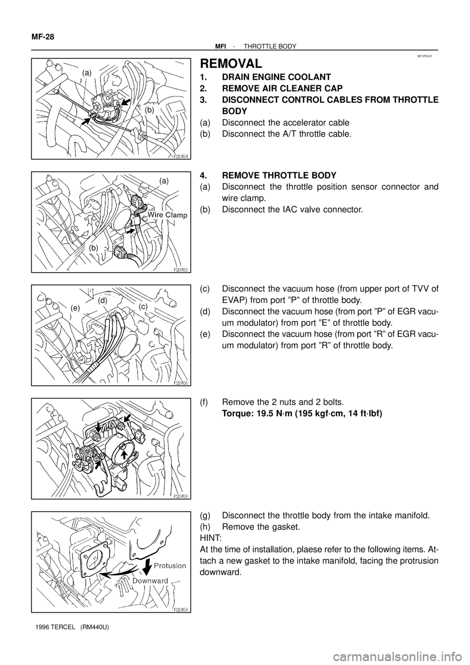
4. REMOVE THROTTLE BODY
(a) Disconnect the throttle position sensor connector and
wire clamp.
(b) Disconnect the IAC valve connector.
(c) Disconnect the vacuum hose (from upper port of TVV of
EVAP) from port ºPº of throttle body.
(d) Disconnect the vacuum hose (from port ºPº of EGR vacu-
um modulator) from port ºEº of throttle body.
(e) Disconnect the vacuum hose (from port ºRº of EGR vacu-
um modulator) from port ºRº of throttle body.
(f) Remove the 2 nuts and 2 bolts.
Torque: 19.5 N´m (195 kgf´cm, 14 ft´lbf)
(g) Disconnect the throttle body from the intake manifold.
(h) Remove the gasket.
HINT:
At the time of installation, plaese refer to the following items. At-
tach a new gasket to the intake manifold, facing the protrusion
downward.
Page 554 of 1202
(j)
(k)
(i)
- MFITHROTTLE BODY
MF-29
1996 TERCEL (RM440U)
(i) Disconnect water bypass hose (from water bypass pipe).
(j) Disconnect the water bypass hose (from water outlet).
(k) Disconnect the air hoses (from PS air control valve).