Page 1366 of 2062
EXTENSION HOUSING
MT−41
1996 T")
Downloaded from www.Manualslib.com manuals search engine MT044−01
Q04410
D00877
Reverse Restrict PinSlotted
Spring Pin
WM0085
Q07553
SST
− MANUAL TRANSMISSION (W59)EXTENSION HOUSING
MT−41
1996 TOYOTA T100 (RM449U)
REPLACEMENT
1. IF NECESSARY, REPLACE REVERSE RESTRICT PIN
(a) Remove the reverse restrict pin.
(1) Using a hexagon wrench, remove the screw plug.
(2) Using a pin punch and hammer, drive out the slotted
spring pin.
(3) Pull off the lever housing and slide out the shaft.
(b) Inspect the reverse restrict pin.
Turn and push the reverse restrict pin by hand.
Check for smooth operation.
(c) Install the reverse restrict pin.
(1) Install the lever housing.
(2) Using a pin punch and hammer, drive in the slotted
spring pin, as shown.
(3) Apply sealant to the plug threads.
Sealant:
Part No. 08833 − 00080, THREE BOND 1344, LOCTITE
242 or equivalent
(4) Install and torque the screw plug.
Torque: 25 N·m (250 kgf·cm, 18 ft·lbf)
2. IF NECESSARY, REPLACE REAR BEARING OUTER
RACE
(a) Using 2 screwdrivers, remove the snap ring.
(b) Using SST, remove the outer race.
SST 09308−00010
Page 1367 of 2062
Downloaded from www.Manualslib.com manuals search engine Q07370
SST
WM0110
SST
Q07371
SST MT−42
− MANUAL TRANSMISSION (W59)EXTENSION HOUSING
1996 TOYOTA T100 (RM449U)
(c) Using SST, install a new outer race.
SST 09950−60010 (09951−00560), 09950−70010
(09951−07150)
(d) Using a screwdriver, install the snap ring.
3. IF NECESSARY, REPLACE EXTENSION HOUSING
OIL SEAL
(a) Using SST, remove the oil seal.
SST 09308−00010 or 09308−10010 w/ output shaft
installed
(b) Using SST and a hammer, drive in a new oil seal.
SST 09950−60010 (09951−00560), 09950−70010
(09951−07150)
Drive in depth: 0 ± 0.5 mm (0 ± 0.020 in.)
Page 1387 of 2062
Downloaded from www.Manualslib.com manuals search engine AT024−01
− AUTOMATIC TRANSMISSIONSHIFT LOCK SYSTEM
AT−19
1360 Author�: Date�:
1996 TOYOTA T100 (RM449U)
SHIFT LOCK SYSTEM
ON−VEHICLE INSPECTION
CHECK SHIFT LOCK SYSTEM
(a) With depressing the brake pedal, check that the tip of the parking lock cable protrudes from the pedal
bracket.
(b) Set the shift position to the P position. With the brake pedal depressed, check the select lock cancel.
(c) Check that the lock pin has no unusual operation sound.
(d) Remove the center cluster finish lower panel. (See page BO−36)
(1) Check that the sliding rod is protruded when the ignition key plate is turned from LOCK position
to ACC position.
(2) Check that the sliding rod is released when the ignition key plate is turned to LOCK position.
If the key interlock solenoid operation is defective, replace the key cylinder.
Page 1396 of 2062

1996 TOYOTA T100 (RM449U)
REMOVAL
1.")
Downloaded from www.Manualslib.com manuals search engine AT02B−02
Q06797
Q06962
3RZ−FE AT−28
− AUTOMATIC TRANSMISSIONAUTOMATIC TRANSMISSION UNIT (A340E)
1996 TOYOTA T100 (RM449U)
REMOVAL
1. REMOVE ATF LEVEL GAUGE
2. REMOVE ENGINE UNDER COVER
3. DISCONNECT THROTTLE CABLE
(a) Loosen the nut and disconnect the cable.
(b) Remove the throttle cable from the clamps.
4. 5VZ−FE:
REMOVE NO.1 THROTTLE CABLE CLAMP
Remove the 2 nuts and No.1 throttle cable clamp.
5. JACK UP VEHICLE
6. REMOVE OIL FILLER PIPE
Remove the bolt and oil filler pipe with the O−ring.
HINT:
At the time of reassembly, please refer to the following item.
Replace used O−ring with a new one.
7. REMOVE PROPELLER SHAFT (See page PR−3)
8. 3RZ−FE:
REMOVE FRONT EXHAUST PIPE
(a) Disconnect the oxygen sensor connector.
(b) Remove the 2 bolts and retainer.
Torque: 48 N·m (490 kgf·cm, 35 ft·lbf)
(c) Loosen the clamp bolt and disconnect the clamp from the
support bracket.
Torque: 19 N·m (195 kgf·cm, 14 ft·lbf)
(d) Remove the 2 bolts and support bracket.
Torque: 71 N·m (730 kgf·cm, 53 ft·lbf)
(e) Remove the 3 nuts, front exhaust pipe and 3 gaskets.
Torque: 62 N·m (630 kgf·cm, 40 ft·lbf)
HINT:
At the time of reassembly, please refer to the following item.
Replace the used 3 gaskets with new ones.
Page 1397 of 2062

AT−29
1996 TOYOTA T100 (RM449U)
9.")
Downloaded from www.Manualslib.com manuals search engine Q06796
5VZ−FE
Q06806
Z18883
A
B
C
Q06986
− AUTOMATIC TRANSMISSIONAUTOMATIC TRANSMISSION UNIT (A340E)
AT−29
1996 TOYOTA T100 (RM449U)
9. 5VZ−FE:
REMOVE FRONT EXHAUST PIPE
(a) Disconnect the oxygen sensor connector.
(b) Remove the 2 bolts and retainer.
Torque: 48 N·m (490 kgf·cm, 35 ft·lbf)
(c) Remove the 3 bolts and support bracket.
Torque: 44 N·m (450 kgf·cm, 33 ft·lbf)
(d) Remove the 3 nuts, front exhaust pipe and 3 gaskets.
Torque: 62 N·m (630 kgf·cm, 40 ft·lbf)
HINT:
At the time of reassembly, please refer to the following item.
Replace the used 3 gaskets with new ones.
10. DISCONNECT SPEEDOMETER CABLE
(a) Loosen the serrated collar with pliers. Do not lose the felt
dust protector and washer.
(b) Disconnect the cable.
11. DISCONNECT NO.2 VEHICLE SPEED SENSOR CON-
NECTOR AND SOLENOID CONNECTOR
12. REMOVE CROSS SHAFT
(a) Remove the clip and disconnect the No.2 gear shifting
rod.
(b) Remove the nut, washer, 4 bolts and the cross shaft.
Torque:
A (Transmission side): 13 N·m (130 kgf·cm, 9 ft·lbf)
B (Frame side): 28 N·m (290 kgf·cm, 21 ft·lbf)
C (Nut): 13 N·m (130 kgf·cm, 9 ft·lbf)
13. REMOVE OIL COOLER PIPE
(a) Remove the bolts and 3 clamps.
(b) Disconnect the 2 oil cooler pipes.
Torque: 34 N·m (350 kgf·cm, 25 ft·lbf)
Page 1406 of 2062

Downloaded from www.Manualslib.com manuals search engine AT0953
SST
AT02G−06
AT3306
Free Lock Hold
Turn
D00843
AT−38
− AUTOMATIC TRANSMISSIONTORQUE CONVERTER CLUTCH AND DRIVE PLATE
1379 Author�: Date�:
1996 TOYOTA T100 (RM449U)
TORQUE CONVERTER CLUTCH
AND DRIVE PLATE
INSPECTION
1. INSPECT ONE−WAY CLUTCH
(a) Install SST in the inner race of one−way clutch.
SST 09350−30020 (09351−32010)
(b) Install SST so that it fits in the notch of the converter hub
and outer race of the one−way clutch.
SST 09350−30020 (09351−32020)
(c) With the torque converter clutch standing on its side,
check that the clutch locks when turned counterclock-
wise, and rotates freely and smoothly clockwise.
If necessary, clean the converter and retest the clutch.
(d) Replace the converter if the clutch still fails the test.
2. MEASURE DRIVE PLATE RUNOUT AND INSPECT
RING GEAR
Set up a dial indicator, measure the drive plate runout.
Maximum runout: 0.20 mm (0.0079 in.)
If runout is not within the specification or if the ring gear is dam-
aged, replace the drive plate.
Torque: 83 N·m (850 kgf·cm, 61 ft·lbf)
Page 1448 of 2062
Downloaded from www.Manualslib.com manuals search engine PR01F−01
− PROPELLER SHAFTTROUBLESHOOTING
PR−1
1419 Author�: Date�:
1996 TOYOTA T100 (RM449U)
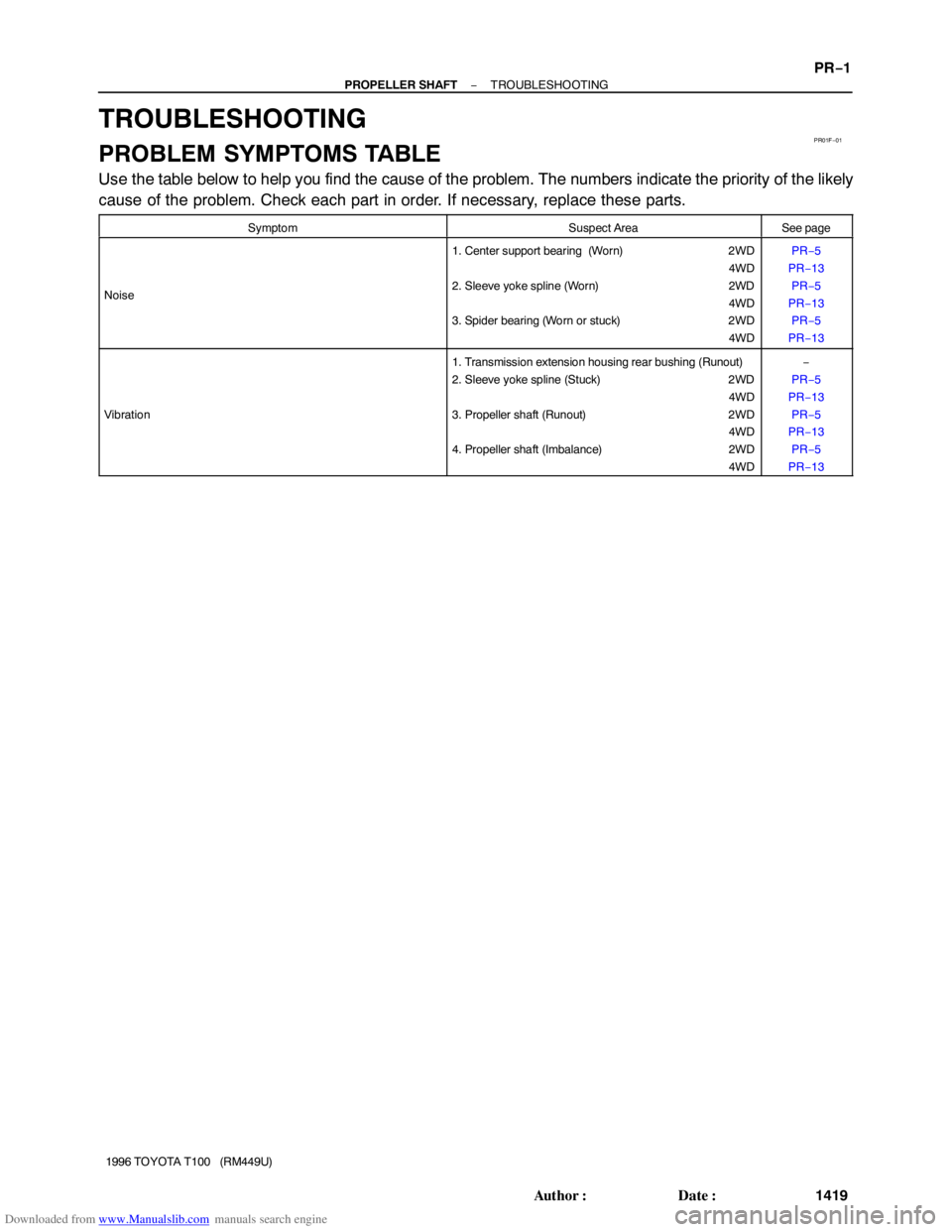
TROUBLESHOOTING
PROBLEM SYMPTOMS TABLE
Use the table below to help you find the cause of the problem. The numbers indicate the priority of the likely
cause of the problem. Check each part in order. If necessary, replace these parts.
SymptomSuspect AreaSee page
Noise
1. Center support bearing (Worn) 2WD
4WD
2. Sleeve yoke spline (Worn) 2WD
4WD
3. Spider bearing (Worn or stuck) 2WD
4WDPR−5
PR−13
PR−5
PR−13
PR−5
PR−13
Vibration
1. Transmission extension housing rear bushing (Runout)
2. Sleeve yoke spline (Stuck) 2WD
4WD
3. Propeller shaft (Runout) 2WD
4WD
4. Propeller shaft (Imbalance) 2WD
4WD−
PR−5
PR−13
PR−5
PR−13
PR−5
PR−13
EXTENSION HOUSING
1996 TOYOTA T100 (RM449U)
(c) Using SST, install a ne")