Page 1517 of 2062
Downloaded from www.Manualslib.com manuals search engine SA0G5−01
R04298
Matchmarks
R04533
FA0858
− SUSPENSION AND AXLEFRONT DIFFERENTIAL CARRIER (4WD)
SA−47
1996 TOYOTA T100 (RM449U)
REMOVAL
1. REMOVE ENGINE UNDER COVER AND DRAIN HYPO-
ID GEAR OIL
2. REMOVE FRONT PROPELLER SHAFT
(See page PR−11)
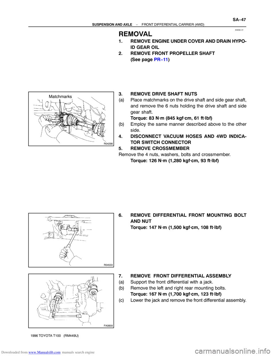
3. REMOVE DRIVE SHAFT NUTS
(a) Place matchmarks on the drive shaft and side gear shaft,
and remove the 6 nuts holding the drive shaft and side
gear shaft.
Torque: 83 N·m (845 kgf·cm, 61 ft·lbf)
(b) Employ the same manner described above to the other
side.
4. DISCONNECT VACUUM HOSES AND 4WD INDICA-
TOR SWITCH CONNECTOR
5. REMOVE CROSSMEMBER
Remove the 4 nuts, washers, bolts and crossmember.
Torque: 126 N·m (1,280 kgf·cm, 93 ft·lbf)
6. REMOVE DIFFERENTIAL FRONT MOUNTING BOLT
AND NUT
Torque: 147 N·m (1,500 kgf·cm, 108 ft·lbf)
7. REMOVE FRONT DIFFERENTIAL ASSEMBLY
(a) Support the front differential with a jack.
(b) Remove the left and right rear mounting bolts.
Torque: 167 N·m (1,700 kgf·cm, 123 ft·lbf)
(c) Lower the jack and remove the front differential assembly.
Page 1521 of 2062
Downloaded from www.Manualslib.com manuals search engine SA2348
SST
Z00641
SST
Z03859
Matchmarks
FA0751
SST
− SUSPENSION AND AXLEFRONT DIFFERENTIAL CARRIER (4WD)
SA−51
1996 TOYOTA T100 (RM449U)
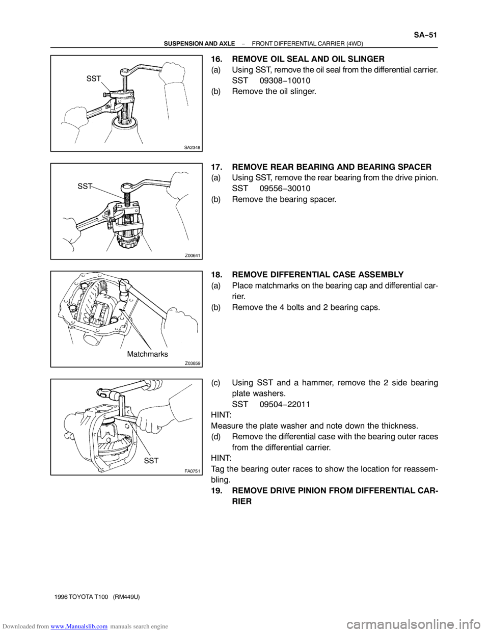
16. REMOVE OIL SEAL AND OIL SLINGER
(a) Using SST, remove the oil seal from the differential carrier.
SST 09308−10010
(b) Remove the oil slinger.
17. REMOVE REAR BEARING AND BEARING SPACER
(a) Using SST, remove the rear bearing from the drive pinion.
SST 09556−30010
(b) Remove the bearing spacer.
18. REMOVE DIFFERENTIAL CASE ASSEMBLY
(a) Place matchmarks on the bearing cap and differential car-
rier.
(b) Remove the 4 bolts and 2 bearing caps.
(c) Using SST and a hammer, remove the 2 side bearing
plate washers.
SST 09504−22011
HINT:
Measure the plate washer and note down the thickness.
(d) Remove the differential case with the bearing outer races
from the differential carrier.
HINT:
Tag the bearing outer races to show the location for reassem-
bling.
19. REMOVE DRIVE PINION FROM DIFFERENTIAL CAR-
RIER
Page 1529 of 2062
Downloaded from www.Manualslib.com manuals search engine Z03851
W00404
SST Front Rear
R01197
SST
R11163SST
SA2347
SST
− SUSPENSION AND AXLEFRONT DIFFERENTIAL CARRIER (4WD)
SA−59
1996 TOYOTA T100 (RM449U)
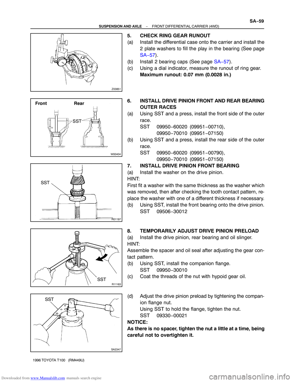
5. CHECK RING GEAR RUNOUT
(a) Install the differential case onto the carrier and install the
2 plate washers to fill the play in the bearing (See page
SA−57).
(b) Install 2 bearing caps (See page SA−57).
(c) Using a dial indicator, measure the runout of ring gear.
Maximum runout: 0.07 mm (0.0028 in.)
6. INSTALL DRIVE PINION FRONT AND REAR BEARING
OUTER RACES
(a) Using SST and a press, install the front side of the outer
race.
SST 09950−60020 (09951−00710),
09950−70010 (09951−07150)
(b) Using SST and a press, install the rear side of the outer
race.
SST 09950−60020 (09951−00790),
09950−70010 (09951−07150)
7. INSTALL DRIVE PINION FRONT BEARING
(a) Install the washer on the drive pinion.
HINT:
First fit a washer with the same thickness as the washer which
was removed, then after checking the tooth contact pattern, re-
place the washer with one of a different thickness if necessary.
(b) Using SST, install the front bearing onto the drive pinion.
SST 09506−30012
8. TEMPORARILY ADJUST DRIVE PINION PRELOAD
(a) Install the drive pinion, rear bearing and oil slinger.
HINT:
Assemble the spacer and oil seal after adjusting the gear con-
tact pattern.
(b) Using SST, install the companion flange.
SST 09950−30010
(c) Coat the threads of the nut with hypoid gear oil.
(d) Adjust the drive pinion preload by tightening the compan-
ion flange nut.
Using SST to hold the flange, tighten the nut.
SST 09330−00021
NOTICE:
As there is no spacer, tighten the nut a little at a time, being
careful not to overtighten it.
Page 1533 of 2062
Downloaded from www.Manualslib.com manuals search engine R02495
Proper ContactHeel ContactFace Contact
Toe ContactFlank Contact Select an adjusting shim that will bring the drive
pinion closer to the gear.
Select an adjusting shim that will shaft the drive
pinion gear away from the ring gear.
FA2008
Washer
Z03850
− SUSPENSION AND AXLEFRONT DIFFERENTIAL CARRIER (4WD)
SA−63
1996 TOYOTA T100 (RM449U)
If the teeth are not contacting properly, use the following chart
to select a proper washer for correction.
Washer thickness
Thickness mm (in.)Thickness mm (in.)
2.27 (0.0894)2.51 (0.0988)
2.30 (0.0906)2.54 (0.1000)
2.33 (0.0917)2.57 (0.1012)
2.36 (0.0929)2.60 (0.1024)
2.39 (0.0941)2.63 (0.1035)
2.42 (0.0953)2.66 (0.1047)
2.45 (0.0965)2.69 (0.1059)
2.48 (0.0976)−
15. INSTALL BEARING SPACER
(a) Remove the companion flange, oil slinger and rear bear-
ing (See page SA−48).
(b) Install a new bearing spacer.
(c) Install the rear bearing and oil slinger.
Page 1604 of 2062
Downloaded from www.Manualslib.com manuals search engine R04283
SST
R04284
SST
R12939
SSTBearing Side
Z17542SST 122.2 ± 1mm
(4.811 ± 0.039 in.) SA−134
− SUSPENSION AND AXLEREAR AXLE SHAFT
1996 TOYOTA T100 (RM449U)
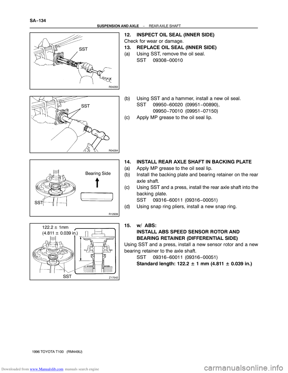
12. INSPECT OIL SEAL (INNER SIDE)
Check for wear or damage.
13. REPLACE OIL SEAL (INNER SIDE)
(a) Using SST, remove the oil seal.
SST 09308−00010
(b) Using SST and a hammer, install a new oil seal.
SST 09950−60020 (09951−00890),
09950−70010 (09951−07150)
(c) Apply MP grease to the oil seal lip.
14. INSTALL REAR AXLE SHAFT IN BACKING PLATE
(a) Apply MP grease to the oil seal lip.
(b) Install the backing plate and bearing retainer on the rear
axle shaft.
(c) Using SST and a press, install the rear axle shaft into the
backing plate.
SST 09316−60011 (09316−00051)
(d) Using snap ring pliers, install a new snap ring.
15. w/ ABS:
INSTALL ABS SPEED SENSOR ROTOR AND
BEARING RETAINER (DIFFERENTIAL SIDE)
Using SST and a press, install a new sensor rotor and a new
bearing retainer to the axle shaft.
SST 09316−60011 (09316−00051)
Standard length: 122.2 ± 1 mm (4.811 ± 0.039 in.)
Page 1609 of 2062
Downloaded from www.Manualslib.com manuals search engine R04163
Matchmarks
SA0I3−01
R08285
− SUSPENSION AND AXLEREAR DIFFERENTIAL CARRIER
SA−139
1996 TOYOTA T100 (RM449U)
REMOVAL
1. DRAIN HYPOID GEAR OIL
2. REMOVE REAR AXLE SHAFTS (See page SA−131)
3. REMOVE PROPELLER SHAFT
(2WD: See page PR−3)
(4WD: See page PR−11)
4. REMOVE DIFFERENTIAL CARRIER ASSEMBLY
(a) Remove the 10 nuts, washers and differential carrier as-
sembly.
Torque: 73 N·m (740 kgf·cm, 54 ft·lbf)
NOTICE:
Be careful not to damage the installation surface.
(b) Remove the gasket.
Page 1611 of 2062
Downloaded from www.Manualslib.com manuals search engine SA2349
SST
R11391SST
SA2348
SST
Z00641
SST
R04324
Matchmarks
− SUSPENSION AND AXLEREAR DIFFERENTIAL CARRIER
SA−141
1996 TOYOTA T100 (RM449U)
6. REMOVE COMPANION FLANGE
(a) Using a chisel and hammer, unstake the staked part of the
nut.
(b) Using SST to hold the flange, remove the nut.
SST 09330−00021
(c) Using SST, remove the companion flange.
SST 09950−30010
7. REMOVE FRONT OIL SEAL
Using SST, remove the oil seal from the differential carrier.
SST 09308−10010
8. REMOVE FRONT BEARING AND BEARING SPECER
(a) Using SST, remove the bearing from the drive pinion.
SST 09556−22010
(b) Remove the 2 washers and bearing spacer. If the front
bearing is damaged or worn, replace the bearing.
9. REMOVE DIFFERENTIAL CASE
(a) Place matchmarks on the bearing cap and differential car-
rier.
(b) Remove the 4 bolts and bearing cap.
Page 1616 of 2062
Downloaded from www.Manualslib.com manuals search engine R04333
SST
SST
SA1143
Boiling Water
R04332
Matchmarks
R04334
R04335
SST SA−146
− SUSPENSION AND AXLEREAR DIFFERENTIAL CARRIER
1996 TOYOTA T100 (RM449U)
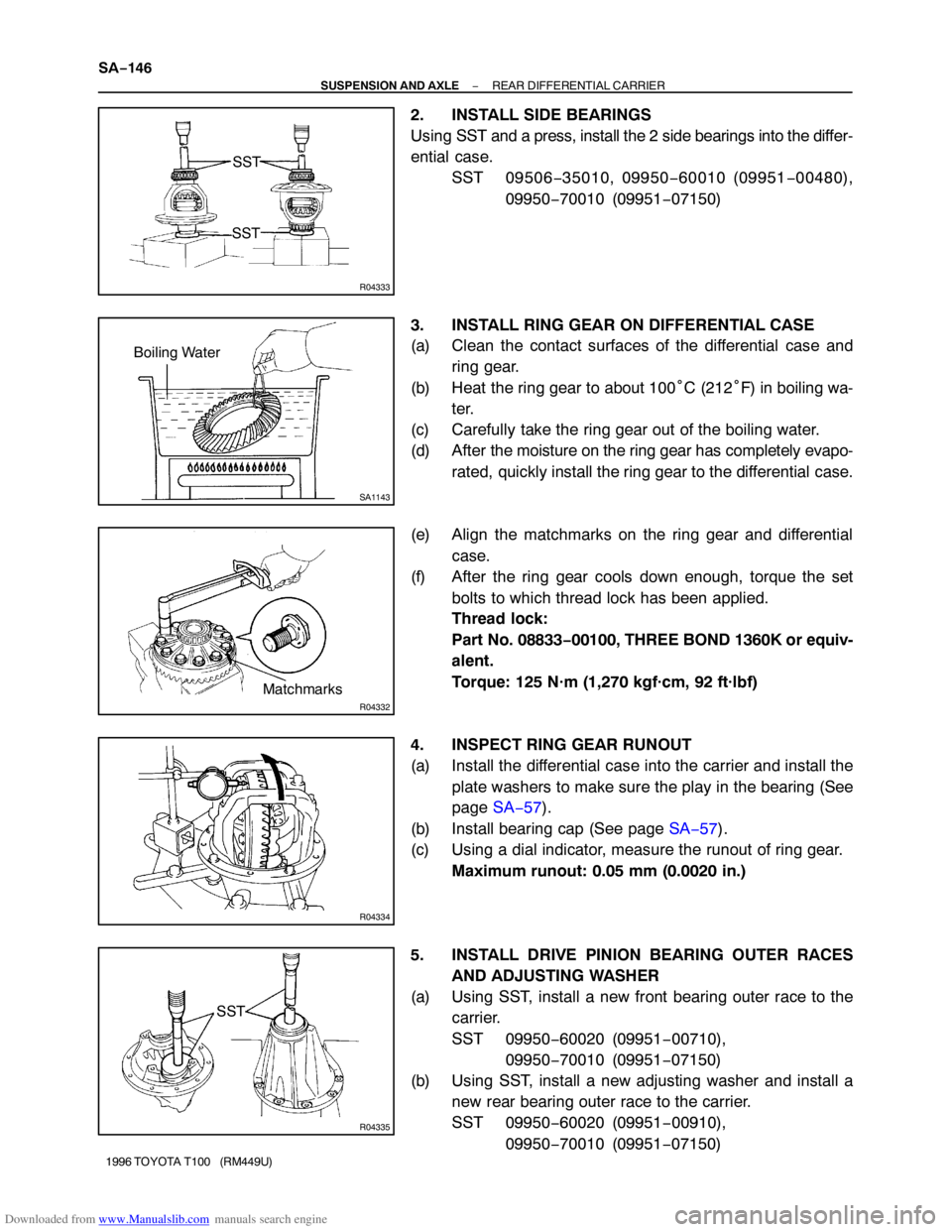
2. INSTALL SIDE BEARINGS
Using SST and a press, install the 2 side bearings into the differ-
ential case.
SST 09506−35010, 09950−60010 (09951−00480),
09950−70010 (09951−07150)
3. INSTALL RING GEAR ON DIFFERENTIAL CASE
(a) Clean the contact surfaces of the differential case and
ring gear.
(b) Heat the ring gear to about 100°C (212°F) in boiling wa-
ter.
(c) Carefully take the ring gear out of the boiling water.
(d) After the moisture on the ring gear has completely evapo-
rated, quickly install the ring gear to the differential case.
(e) Align the matchmarks on the ring gear and differential
case.
(f) After the ring gear cools down enough, torque the set
bolts to which thread lock has been applied.
Thread lock:
Part No. 08833−00100, THREE BOND 1360K or equiv-
alent.
Torque: 125 N·m (1,270 kgf·cm, 92 ft·lbf)
4. INSPECT RING GEAR RUNOUT
(a) Install the differential case into the carrier and install the
plate washers to make sure the play in the bearing (See
page SA−57).
(b) Install bearing cap (See page SA−57).
(c) Using a dial indicator, measure the runout of ring gear.
Maximum runout: 0.05 mm (0.0020 in.)
5. INSTALL DRIVE PINION BEARING OUTER RACES
AND ADJUSTING WASHER
(a) Using SST, install a new front bearing outer race to the
carrier.
SST 09950−60020 (09951−00710),
09950−70010 (09951−07150)
(b) Using SST, install a new adjusting washer and install a
new rear bearing outer race to the carrier.
SST 09950−60020 (09951−00910),
09950−70010 (09951−07150)


