Page 1246 of 2062
Downloaded from www.Manualslib.com manuals search engine P20582
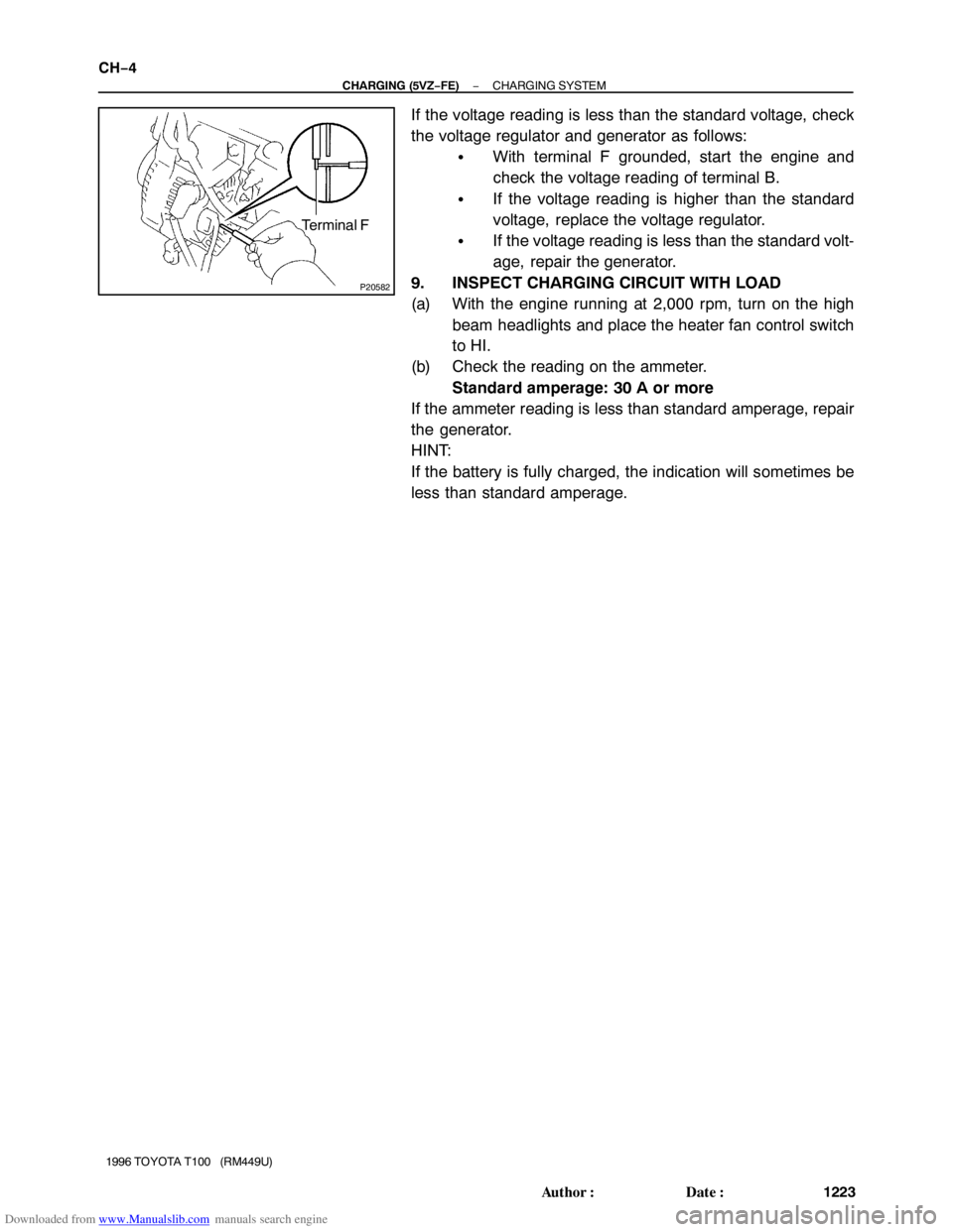
Terminal F
CH−4
− CHARGING (5VZ−FE)CHARGING SYSTEM
1223 Author�: Date�:
1996 TOYOTA T100 (RM449U)
If the voltage reading is less than the standard voltage, check
the voltage regulator and generator as follows:
�With terminal F grounded, start the engine and
check the voltage reading of terminal B.
�If the voltage reading is higher than the standard
voltage, replace the voltage regulator.
�If the voltage reading is less than the standard volt-
age, repair the generator.
9. INSPECT CHARGING CIRCUIT WITH LOAD
(a) With the engine running at 2,000 rpm, turn on the high
beam headlights and place the heater fan control switch
to HI.
(b) Check the reading on the ammeter.
Standard amperage: 30 A or more
If the ammeter reading is less than standard amperage, repair
the generator.
HINT:
If the battery is fully charged, the indication will sometimes be
less than standard amperage.
Page 1371 of 2062
Downloaded from www.Manualslib.com manuals search engine AT022−06
OR0004
SST
OR0005
SST
− AUTOMATIC TRANSMISSIONEXTENSION HOUSING OIL SEAL (A340E)
AT−3
1344 Author�: Date�:
1996 TOYOTA T100 (RM449U)
EXTENSION HOUSING OIL SEAL
(A340E)
ON−VEHICLE REPAIR
1. REMOVE PROPELLER SHAFT (See page PR−3)
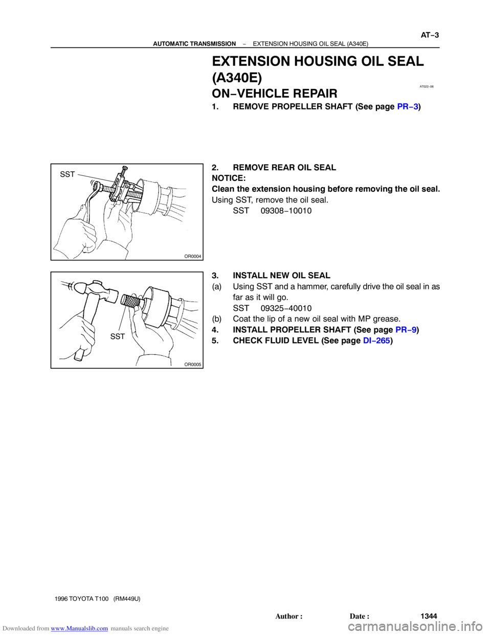
2. REMOVE REAR OIL SEAL
NOTICE:
Clean the extension housing before removing the oil seal.
Using SST, remove the oil seal.
SST 09308−10010
3. INSTALL NEW OIL SEAL
(a) Using SST and a hammer, carefully drive the oil seal in as
far as it will go.
SST 09325−40010
(b) Coat the lip of a new oil seal with MP grease.
4. INSTALL PROPELLER SHAFT (See page PR−9)
5. CHECK FLUID LEVEL (See page DI−265)
Page 1372 of 2062
Downloaded from www.Manualslib.com manuals search engine AT023−02
Q06961
3RZ−FE
Z14780
5VZ−FE
Q06981
AT−4
− AUTOMATIC TRANSMISSIONSENSOR ROTOR (A340E)
1345 Author�: Date�:
1996 TOYOTA T100 (RM449U)
SENSOR ROTOR (A340E)
ON−VEHICLE REPAIR
1. REMOVE PROPELLER SHAFT (See page PR−3)
2. DISCONNECT SPEEDOMETER CABLE AND RE-
MOVE SPEEDOMETER DRIVEN GEAR
(See page AT−8)
3. REMOVE NO.2 VEHICLE SPEED SENSOR
(See page AT−10)
4. JACK UP TRANSMISSION SLIGHTLY
Securely support the transmission on a transmission jack. Lift
the transmission slightly from the crossmember.
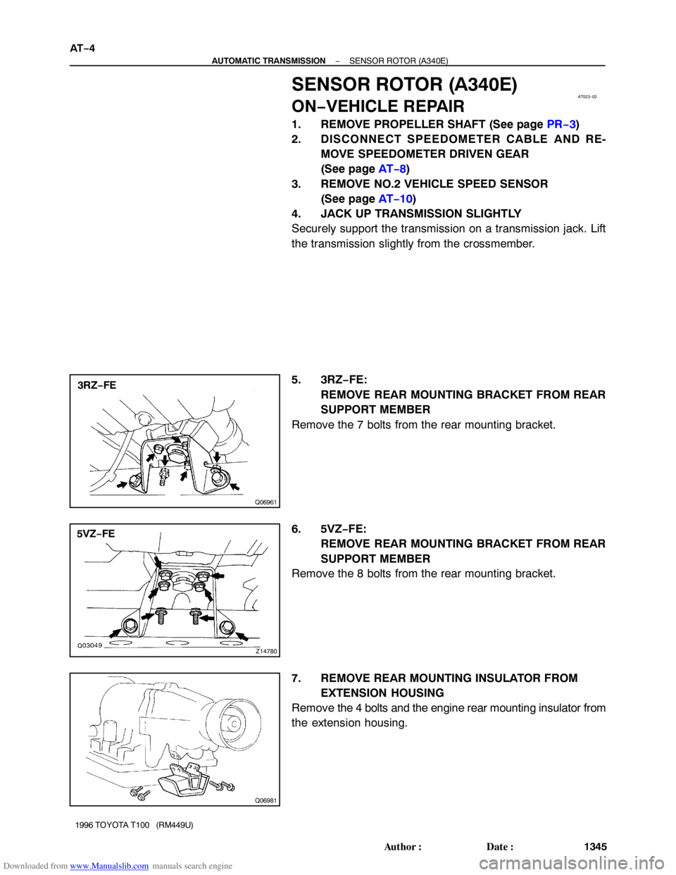
5. 3RZ−FE:
REMOVE REAR MOUNTING BRACKET FROM REAR
SUPPORT MEMBER
Remove the 7 bolts from the rear mounting bracket.
6. 5VZ−FE:
REMOVE REAR MOUNTING BRACKET FROM REAR
SUPPORT MEMBER
Remove the 8 bolts from the rear mounting bracket.
7. REMOVE REAR MOUNTING INSULATOR FROM
EXTENSION HOUSING
Remove the 4 bolts and the engine rear mounting insulator from
the extension housing.
Page 1376 of 2062
Downloaded from www.Manualslib.com manuals search engine Q04730
AT01W−02
Q06873
Z15613
A340E
SST
SST
A340F
Q07623
A340ESST
SST A340F
AT−8
− AUTOMATIC TRANSMISSIONSPEEDOMETER DRIVEN GEAR
1349 Author�: Date�:
1996 TOYOTA T100 (RM449U)
SPEEDOMETER DRIVEN GEAR
ON−VEHICLE REPAIR
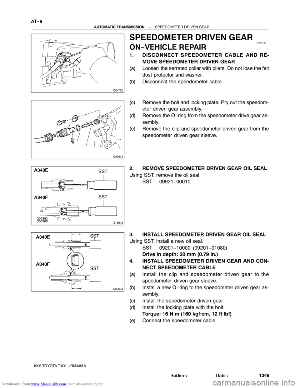
1. DISCONNECT SPEEDOMETER CABLE AND RE-
MOVE SPEEDOMETER DRIVEN GEAR
(a) Loosen the serrated collar with pliers. Do not lose the felt
dust protector and washer.
(b) Disconnect the speedometer cable.
(c) Remove the bolt and locking plate. Pry out the speedom-
eter driven gear assembly.
(d) Remove the O−ring from the speedometer drive gear as-
sembly.
(e) Remove the clip and speedometer driven gear from the
speedometer driven gear sleeve.
2. REMOVE SPEEDOMETER DRIVEN GEAR OIL SEAL
Using SST, remove the oil seal.
SST 09921−00010
3. INSTALL SPEEDOMETER DRIVEN GEAR OIL SEAL
Using SST, install a new oil seal.
SST 09201−10000 (09201−01080)
Drive in depth: 20 mm (0.79 in.)
4. INSTALL SPEEDOMETER DRIVEN GEAR AND CON-
NECT SPEEDOMETER CABLE
(a) Install the clip and speedometer driven gear to the
speedometer driven gear sleeve.
(b) Install a new O−ring to the speedometer driven gear as-
sembly.
(c) Install the speedometer driven gear.
(d) Install the locking plate with the bolt.
Torque: 16 N·m (160 kgf·cm, 12 ft·lbf)
(e) Connect the speedometer cable.
Page 1378 of 2062
Downloaded from www.Manualslib.com manuals search engine AT01X−01
Z14781
A340E
Z14782
A340F AT−10
− AUTOMATIC TRANSMISSIONVEHICLE SPEED SENSOR
1351 Author�: Date�:
1996 TOYOTA T100 (RM449U)
VEHICLE SPEED SENSOR
ON−VEHICLE REPAIR
1. DISCONNECT NO.2 VEHICLE SPEED SENSOR CON-
NECTOR
2. REMOVE NO.2 VEHICLE SPEED SENSOR
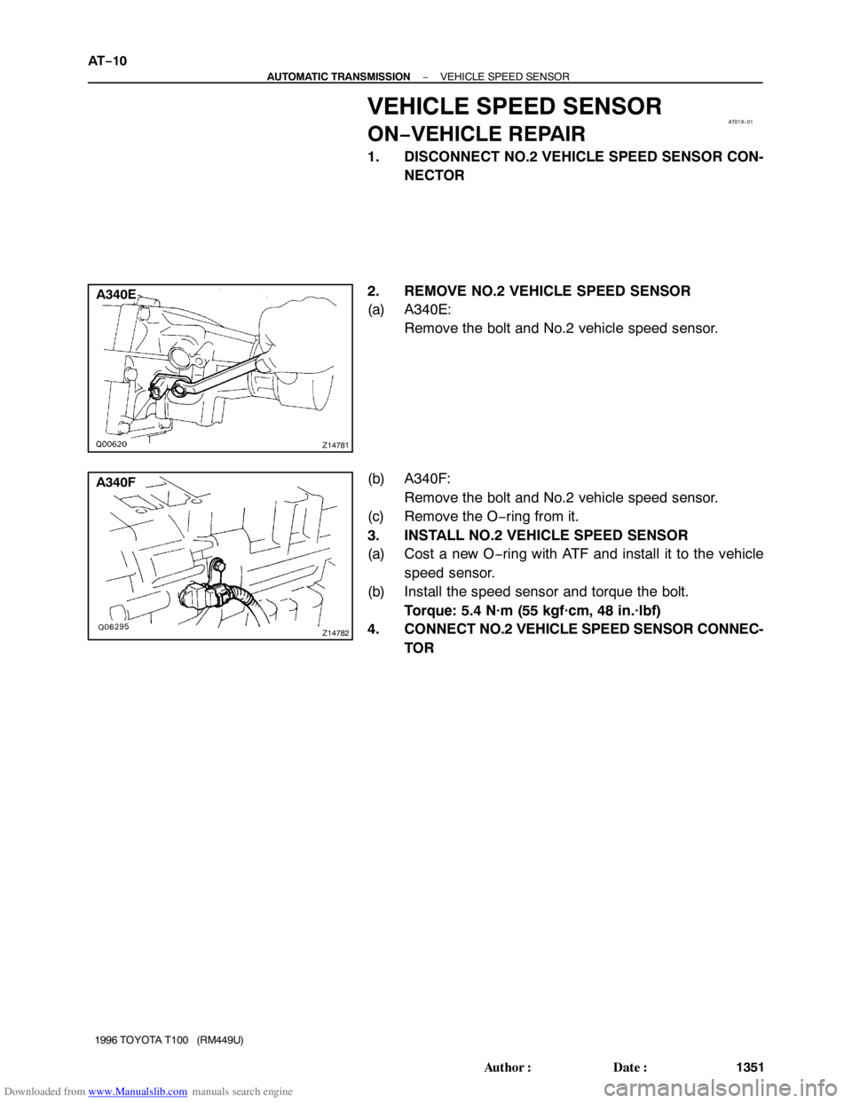
(a) A340E:
Remove the bolt and No.2 vehicle speed sensor.
(b) A340F:
Remove the bolt and No.2 vehicle speed sensor.
(c) Remove the O−ring from it.
3. INSTALL NO.2 VEHICLE SPEED SENSOR
(a) Cost a new O−ring with ATF and install it to the vehicle
speed sensor.
(b) Install the speed sensor and torque the bolt.
Torque: 5.4 N·m (55 kgf·cm, 48 in.·lbf)
4. CONNECT NO.2 VEHICLE SPEED SENSOR CONNEC-
TOR
Page 1379 of 2062
Downloaded from www.Manualslib.com manuals search engine Q07624
AT01Y−01
− AUTOMATIC TRANSMISSIONPARK/NEUTRAL POSITION (PNP) SWITCH
AT−11
1352 Author�: Date�:
1996 TOYOTA T100 (RM449U)
PARK/NEUTRAL POSITION (PNP)
SWITCH
ON−VEHICLE REPAIR
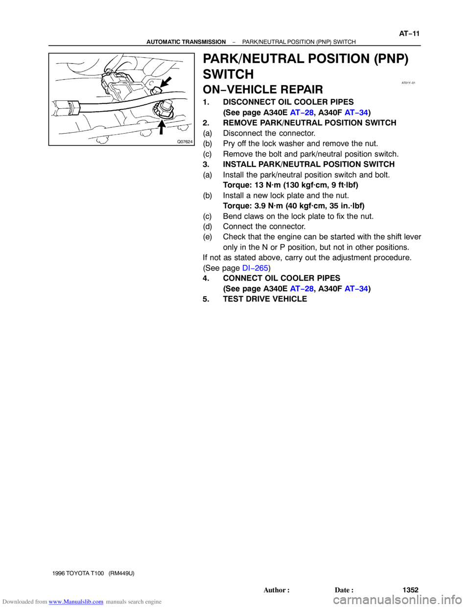
1. DISCONNECT OIL COOLER PIPES
(See page A340E AT−28, A340F AT−34)
2. REMOVE PARK/NEUTRAL POSITION SWITCH
(a) Disconnect the connector.
(b) Pry off the lock washer and remove the nut.
(c) Remove the bolt and park/neutral position switch.
3. INSTALL PARK/NEUTRAL POSITION SWITCH
(a) Install the park/neutral position switch and bolt.
Torque: 13 N·m (130 kgf·cm, 9 ft·lbf)
(b) Install a new lock plate and the nut.
Torque: 3.9 N·m (40 kgf·cm, 35 in.·lbf)
(c) Bend claws on the lock plate to fix the nut.
(d) Connect the connector.
(e) Check that the engine can be started with the shift lever
only in the N or P position, but not in other positions.
If not as stated above, carry out the adjustment procedure.
(See page DI−265)
4. CONNECT OIL COOLER PIPES
(See page A340E AT−28, A340F AT−34)
5. TEST DRIVE VEHICLE
Page 1380 of 2062
Downloaded from www.Manualslib.com manuals search engine AT0ZJ−01
Q07625
AT3168SST
AT0103
AT−12
− AUTOMATIC TRANSMISSIONVALVE BODY ASSEMBLY
1353 Author�: Date�:
1996 TOYOTA T100 (RM449U)
VALVE BODY ASSEMBLY
ON−VEHICLE REPAIR
CAUTION:
When working with FIPG material, you must observe the
followings.
�Using a razor blade and a gasket scraper, remove all
oil FIPG material from the gasket surfaces.
�Remove all loose material to thoroughly clean all
components.
�Clean both sealing surfaces with a non−residue sol-
vent.
�Apply FIPG in an approx. 1 mm (0.04 in.) wide bead
along the sealing surface.
�Parts must be assembled within 10 minutes of ap-
plication. Otherwise, the FIPG material must be re-
moved and reapplied.
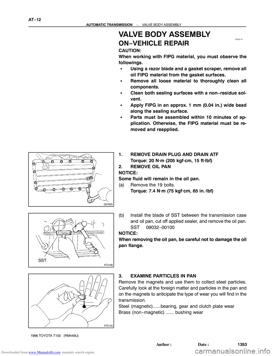
1. REMOVE DRAIN PLUG AND DRAIN ATF
Torque: 20 N·m (205 kgf·cm, 15 ft·lbf)
2. REMOVE OIL PAN
NOTICE:
Some fluid will remain in the oil pan.
(a) Remove the 19 bolts.
Torque: 7.4 N·m (75 kgf·cm, 65 in.·lbf)
(b) Install the blade of SST between the transmission case
and oil pan, cut off applied sealer, and remove the oil pan.
SST 09032−00100
NOTICE:
When removing the oil pan, be careful not to damage the oil
pan flange.
3. EXAMINE PARTICLES IN PAN
Remove the magnets and use them to collect steel particles.
Carefully look at the foreign matter and particles in the pan and
on the magnets to anticipate the type of wear you will find in the
transmission.
Steel (magnetic)......bearing, gear and clutch plate wear
Brass (non−magnetic) ...... bushing wear
Page 1385 of 2062
Downloaded from www.Manualslib.com manuals search engine AT1366
AT020−01
AT2000
AT2001
AT2000
AT1366
− AUTOMATIC TRANSMISSIONPARKING LOCK PAWL
AT−17
1358 Author�: Date�:
1996 TOYOTA T100 (RM449U)
PARKING LOCK PAWL
ON−VEHICLE REPAIR
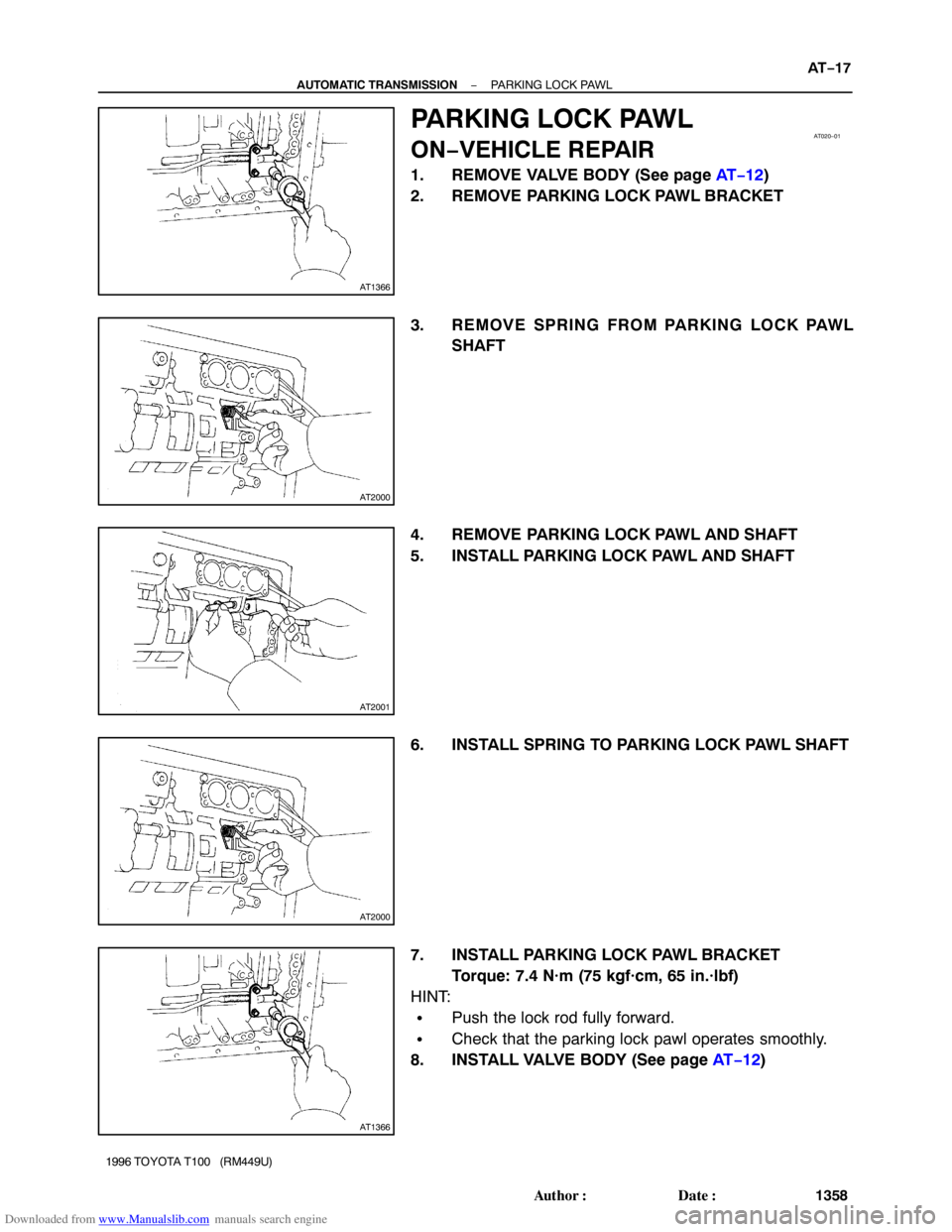
1. REMOVE VALVE BODY (See page AT−12)
2. REMOVE PARKING LOCK PAWL BRACKET
3. REMOVE SPRING FROM PARKING LOCK PAWL
SHAFT
4. REMOVE PARKING LOCK PAWL AND SHAFT
5. INSTALL PARKING LOCK PAWL AND SHAFT
6. INSTALL SPRING TO PARKING LOCK PAWL SHAFT
7. INSTALL PARKING LOCK PAWL BRACKET
Torque: 7.4 N·m (75 kgf·cm, 65 in.·lbf)
HINT:
�Push the lock rod fully forward.
�Check that the parking lock pawl operates smoothly.
8. INSTALL VALVE BODY (See page AT−12)