Page 1907 of 2062
Downloaded from www.Manualslib.com manuals search engine S
UP S : Radio + Tape player U : Radio − Tape Player (Built−in Power Amplifier)
P : Radio − Tape Player (Separate Power Amplifier)
Ye s
Ye s
Ye s No
No
NoRadio assembly faulty. 10 Tape Player POWER COMING IN, BUT TAPE PLAYER NOT OPERATION
Tape player faulty. Is radio operating normally?Cassette tape faulty. Functions OK if different cassette tape inserted?
Is there, continuity in speaker wire harness? Speaker wire harness faulty.
Temporarily install another speaker. Functions OK? Speaker faulty.Ye s
No
P
S
Ye sNo
P
UTape player faulty.
Radio assembly faulty.
Power amplifier faulty. Recheck system after
repair. Hissing sound from speaker?
Radio assembly faulty. Recheck system after repair.
SU
BE−72
− BODY ELECTRICALAUDIO SYSTEM
1996 TOYOTA T100 (RM449U)
Page 1909 of 2062
Downloaded from www.Manualslib.com manuals search engine 12 Tape Player SOUND QUALITY POOR (VOLUME FAINT)
S : Radio + Tape Player U : Radio − Tape Player (Built−in Power Amplifier)
P : Radio − Tape Player (Separate Power Amplifier)
Functions OK if different cassette tape inserted? Cassette tape faulty.
NoYe s
No
No
NoNo Ye s
Ye s
Ye s
Ye s Operates normally after cleaning the heads?
Head dirty.
Install properly.
Speaker faulty. Is radio operating normally?
Is speaker properly installed?
Temporarily install another speaker.
Functions OK?Radio assembly faulty.
S
U
PTape player faulty.
Radio assembly faulty.
Radio assembly faulty.
Recheck system after repair.
BE−74
− BODY ELECTRICALAUDIO SYSTEM
1996 TOYOTA T100 (RM449U)
Page 1910 of 2062
Downloaded from www.Manualslib.com manuals search engine S
UPS : Radio + Tape Player U : Radio − Tape Player (Built−in Power Amplifier)
P : Radio − Tape Player (Separate Power Amplifier)Tape player faulty.
Radio assembly faulty. 13 Tape Player TAPE JAMMED, MALFUNCTION WITH TAPE SPEED OR AUTO−REVERSE
Functions OK if different tape (less than 120 mins.)
is inserted?
Is there a foreign object inside tape player?
Operates normally after cleaning the heads?Cassette tape faulty.
Remove foreign object.
Head dirty. No
No
NoYe s
Ye s
Ye s
14 Tape Player APS, SKIP, RPT BUTTONS NOT OPERATING
S : Radio + Tape Player U : Radio − Tape Player (Built−in Power Amplifier)
P : Radio − Tape Player (Separate Power Amplifier)
Functions OK if different cassette tape inserted? Radio assembly faulty.
Ye s
Cassette tape faulty.(Less than 3 secs. of silence between songs (APS, RPT). Less than 15 secs.of silence (SKIP).)
No
− BODY ELECTRICALAUDIO SYSTEM
BE−75
1996 TOYOTA T100 (RM449U)
Page 1911 of 2062
Downloaded from www.Manualslib.com manuals search engine S : Radio + Tape Player U : Radio − Tape Player (Built−in Power Amplifier)
P : Radio − Tape − CD Player (Separate Power Amplifier)
15 Tape Player
No
Radio assembly faulty. CASSETTE TAPE WILL NOT EJECT
Is tape player operating normally?
OK Is radio operating normally?
NG
Check if DOME fuse is OK? Replace fuse.
Is B + applied to power amplifier? Ye s
Ye s
Ye s
Ye s
Ye sNo
No
No Cassette tape jammed.
Tape player faulty. S
UP
S
UPB + wire harness faulty.
Is B + applied to tape player?
Is B + applied to radio assembly?Is there continuity in
B+ wire harness between
power amplifier and
radio assembly.Power amplifier
faulty.
No
Radio assembly faulty. Tape player faulty. S
UP
B + wire harness faulty.
P
SU BE−76
− BODY ELECTRICALAUDIO SYSTEM
1996 TOYOTA T100 (RM449U)
Page 1916 of 2062
Downloaded from www.Manualslib.com manuals search engine BE1PK−02
− BODY ELECTRICALANTENNA
BE−81
1881 Author�: Date�:
1996 TOYOTA T100 (RM449U)
ANTENNA
INSPECTION
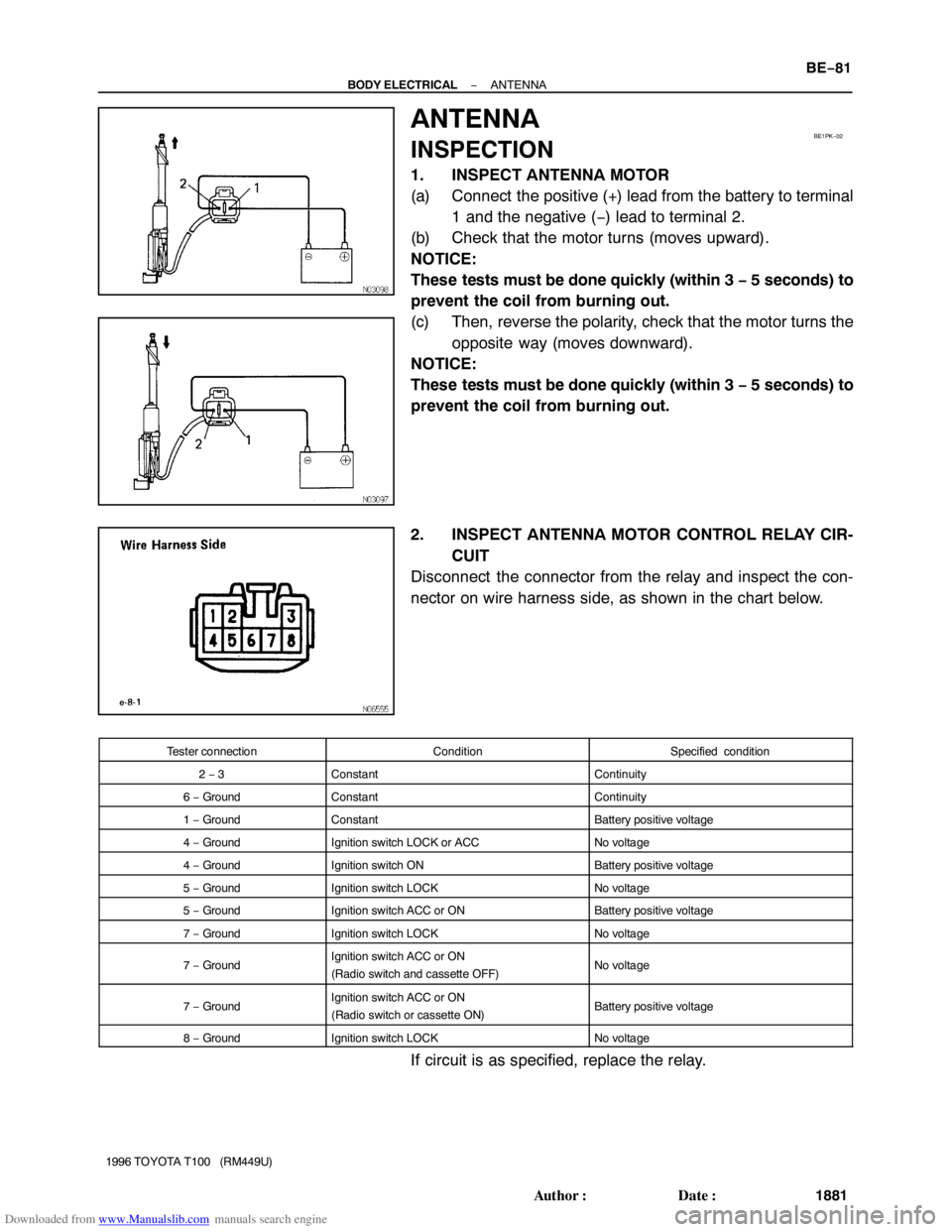
1. INSPECT ANTENNA MOTOR
(a) Connect the positive (+) lead from the battery to terminal
1 and the negative (−) lead to terminal 2.
(b) Check that the motor turns (moves upward).
NOTICE:
These tests must be done quickly (within 3 − 5 seconds) to
prevent the coil from burning out.
(c) Then, reverse the polarity, check that the motor turns the
opposite way (moves downward).
NOTICE:
These tests must be done quickly (within 3 − 5 seconds) to
prevent the coil from burning out.
2. INSPECT ANTENNA MOTOR CONTROL RELAY CIR-
CUIT
Disconnect the connector from the relay and inspect the con-
nector on wire harness side, as shown in the chart below.
Tester connectionConditionSpecified condition
2 − 3ConstantContinuity
6 − GroundConstantContinuity
1 − GroundConstantBattery positive voltage
4 − GroundIgnition switch LOCK or ACCNo voltage
4 − GroundIgnition switch ONBattery positive voltage
5 − GroundIgnition switch LOCKNo voltage
5 − GroundIgnition switch ACC or ONBattery positive voltage
7 − GroundIgnition switch LOCKNo voltage
7 − GroundIgnition switch ACC or ON
(Radio switch and cassette OFF)No voltage
7 − GroundIgnition switch ACC or ON
(Radio switch or cassette ON)Battery positive voltage
8 − GroundIgnition switch LOCKNo voltage
If circuit is as specified, replace the relay.


