Page 1201 of 2062

Downloaded from www.Manualslib.com manuals search engine P25593
(1)
(2)
(3)
(4) (5) (6) (7)
Long
Short
Lead Terminal
P25597
40 mm
37 mm
20 mm Wooden Block
Contact
Plate
(kgf/cm2)
=
100 kgf
Ram diameter (cm)
2
2
2Ram diameter (in.) (psi)
=
x 3.14 (π) x 3.14 (π)
2
(kPa) = (kgf/cm
2) x 98.1
(kPa) = (psi) x 6.9221 lbf
P25596
SST
ST−12
− STARTING (3RZ−FE)STARTER
1996 TOYOTA T100 (RM449U)
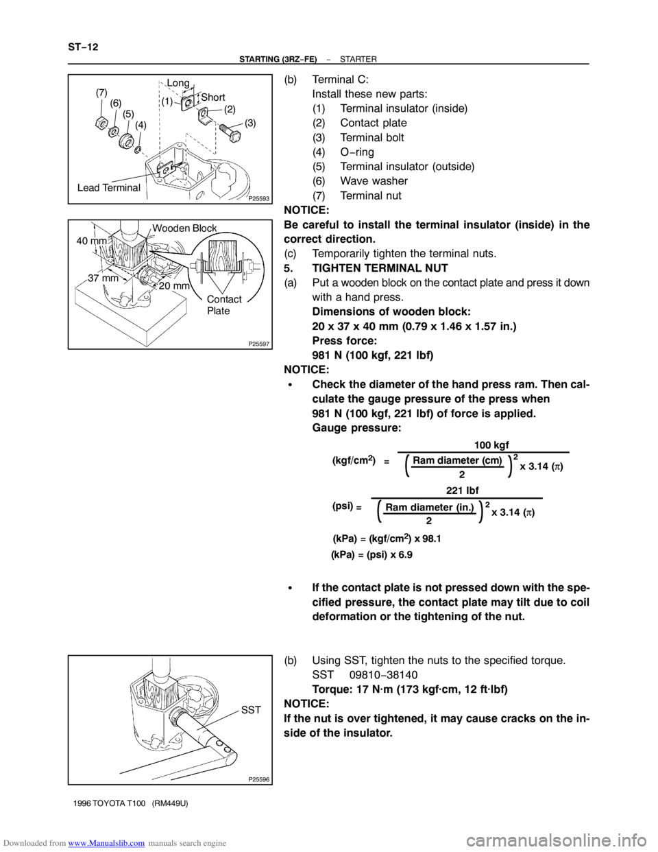
(b) Terminal C:
Install these new parts:
(1) Terminal insulator (inside)
(2) Contact plate
(3) Terminal bolt
(4) O−ring
(5) Terminal insulator (outside)
(6) Wave washer
(7) Terminal nut
NOTICE:
Be careful to install the terminal insulator (inside) in the
correct direction.
(c) Temporarily tighten the terminal nuts.
5. TIGHTEN TERMINAL NUT
(a) Put a wooden block on the contact plate and press it down
with a hand press.
Dimensions of wooden block:
20 x 37 x 40 mm (0.79 x 1.46 x 1.57 in.)
Press force:
981 N (100 kgf, 221 lbf)
NOTICE:
�Check the diameter of the hand press ram. Then cal-
culate the gauge pressure of the press when
981 N (100 kgf, 221 lbf) of force is applied.
Gauge pressure:
�If the contact plate is not pressed down with the spe-
cified pressure, the contact plate may tilt due to coil
deformation or the tightening of the nut.
(b) Using SST, tighten the nuts to the specified torque.
SST 09810−38140
Torque: 17 N·m (173 kgf·cm, 12 ft·lbf)
NOTICE:
If the nut is over tightened, it may cause cracks on the in-
side of the insulator.
Page 1202 of 2062
Downloaded from www.Manualslib.com manuals search engine P25589
− STARTING (3RZ−FE)STARTER
ST−13
1996 TOYOTA T100 (RM449U)
6. CLEAN CONTACT SURFACES OF CONTACT PLATE
AND PLUNGER
Clean the contact surfaces of the remaining contact plate and
plunger with a dry shop rag.
7. REINSTALL MAGNETIC SWITCH END COVER
Install the plunger, new gasket, end cover and lead clamp with
the 3 bolts.
Torque:
1.2 kW, 1.4 kW type: 2.5 N·m (25 kgf·cm, 22 in.·lbf)
1.8 kW, 2.0 kW type: 3.6 N·m (35 kgf·cm, 30 in.·lbf)
Page 1203 of 2062
Downloaded from www.Manualslib.com manuals search engine ST031−02
ST−14
− STARTING (3RZ−FE)STARTER
1996 TOYOTA T100 (RM449U)
REASSEMBLY
Reassembly is in the reverse order of disassembly (See page ST−4).
Page 1204 of 2062

Downloaded from www.Manualslib.com manuals search engine ST032−02
P14894
Terminal 50
Terminal C
Battery
P14895
P14896
P14897
Terminal 30Ammeter
Battery
− STARTING (3RZ−FE)STARTER
ST−15
1996 TOYOTA T100 (RM449U)
TEST
NOTICE:
These tests must be done within 3 to 5 seconds to avoid
burning out the coil.
1. DO PULL−IN TEST
(a) Disconnect the field coil lead wire from terminal C.
(b) Connect the battery to the magnetic switch as shown.
Check that the clutch pinion gear moves outward.
2. DO HOLD−IN TEST
With battery connected as above with the clutch pinion gear
out, disconnect the negative (−) lead from terminal C. Check
that the pinion gear remains out.
3. INSPECT CLUTCH PINION GEAR RETURN
Disconnect the negative (−) lead from the switch body.
Check that the clutch pinion gear returns inward.
4. DO NO−LOAD PERFORMANCE TEST
(a) Connect the battery and ammeter to the starter as shown.
(b) Check that the starter rotates smoothly and steadily with
the pinion gear moving out. Check that the ammeter
reads the specified current.
Specified current:
1.2 kW, 1.4 kW type
90 A or less at 11.5 V
1.8 kW, 2.0 kW type
100 A or less at 11.5 V
Page 1205 of 2062
Downloaded from www.Manualslib.com manuals search engine ST033−02
ST−16
− STARTING (3RZ−FE)STARTER
1996 TOYOTA T100 (RM449U)
INSTALLATION
Installation is in the reverse order of removal (See page ST−3).
Page 1206 of 2062
Downloaded from www.Manualslib.com manuals search engine P07170
Ohmmeter
No
ContinuityContinuity
Ohmmeter 1
3
25ST034−02
P07171
Ohmmeter
Continuity
Battery 1
2 35
− STARTING (3RZ−FE)STARTER RELAY
ST−17
1186 Author�: Date�:
1996 TOYOTA T100 (RM449U)
STARTER RELAY
INSPECTION
1. REMOVE STARTER RELAY (Marking: ST)
HINT:
The relay is located in the No. 1 junction block on the driver’s
side.
2. INSPECT STARTER RELAY CONTINUITY
(a) Using an ohmmeter, check that there is continuity be-
tween terminals 1 and 2.
If there is no continuity, replace the relay.
(b) Check that there is no continuity between terminals 3 and
5.
If there is continuity, replace the relay.
3. INSPECT STARTER RELAY OPERATION
(a) Apply battery voltage across terminals 1 and 2.
(b) Using an ohmmeter, check that there is continuity be-
tween terminals 3 and 5.
If there is no continuity, replace the relay.
4. REINSTALL STARTER RELAY
Page 1207 of 2062
Downloaded from www.Manualslib.com manuals search engine ST – STARTING (5VZ-FE)
STARTER ST-1
STARTER RELAY ST-16
Page 1208 of 2062
Downloaded from www.Manualslib.com manuals search engine ST036−04
P20589
Starter Connector
Starter WireStarter
− STARTING (5VZ−FE)STARTER
ST−1
1187 Author�: Date�:
1996 TOYOTA T100 (RM449U)
STARTER
COMPONENTS