Page 1115 of 2062
Downloaded from www.Manualslib.com manuals search engine CO05X−01
P20967Jiggle Valve
− COOLING (5VZ−FE)THERMOSTAT
CO−11
1996 TOYOTA T100 (RM449U)
INSTALLATION
1. INSTALL THERMOSTAT
(a) Place a new gasket to the thermostat.
(b) Install the thermostat with the jiggle valve downward.
(c) Install the water inlet with the 3 bolts.
Torque: 20 N·m (200 kgf·cm, 14 ft·lbf)
2. CONNECT LOWER RADIATOR HOSE
3. FILL WITH ENGINE COOLANT
4. START ENGINE AND CHECK FOR LEAKS
Page 1117 of 2062

Downloaded from www.Manualslib.com manuals search engine CO05Z−03
Z02362
Radiator Cap Tester
Radiator Cap
P14264
− COOLING (5VZ−FE)RADIATOR
CO−13
1996 TOYOTA T100 (RM449U)
ON−VEHICLE INSPECTION
1. REMOVE RADIATOR CAP
CAUTION:
To avoid the danger of being burned, do not remove the ra-
diator cap while the engine and radiator are still hot, as fluid
and steam can be blown out under pressure.
2. INSPECT RADIATOR CAP
NOTICE:
If the radiator cap has contaminations, always rinse it with
water.
Using a radiator cap tester, pump the tester and measure the
relief valve opening pressure.
Standard opening pressure:
74 − 103 kPa
(0.75 − 1.05 kgf/cm
2, 10.7 − 14.9 psi)
Minimum opening pressure:
59 kPa (0.6 kgf/cm
2, 8.5 psi)
HINT:
Use the tester’s maximum reading as the opening pressure.
If the opening pressure is less than minimum, replace the radia-
tor cap.
3. INSPECT COOLING SYSTEM FOR LEAKS
(a) Fill the radiator with coolant and attach a radiator cap tes-
ter.
(b) Warm up the engine.
(c) Pump it to 118 kPa (1.2 kgf/cm
2, 17.1 psi), and check that
the pressure does not drop.
If the pressure drops, check the hoses, radiator or water pump
for leaks. If no external leaks are found, check the heater core,
cylinder block and head.
4. REINSTALL RADIATOR CAP
Page 1120 of 2062
Downloaded from www.Manualslib.com manuals search engine CO061−01
P20524
P20523
CO−16
− COOLING (5VZ−FE)RADIATOR
1996 TOYOTA T100 (RM449U)
REMOVAL
1. DRAIN ENGINE COOLANT
2. REMOVE RADIATOR GRILLE
(a) Remove the 4 screws, and clearance lights.
(b) Remove the 4 screws, 11 clips and radiator grille.
3. DISCONNECT UPPER RADIATOR HOSE
4. DISCONNECT RADIATOR RESERVOIR HOSE
5. DISCONNECT LOWER RADIATOR HOSE
6. REMOVE RADIATOR NO.2 FAN SHROUD
7. A/T:
DISCONNECT OIL COOLER HOSES
8. REMOVE RADIATOR
Remove the 4 bolts and radiator.
Torque:12 N·m (120 kgf·cm, 8.7 ft·lbf)
HINT:
Insert the tabs of the radiator support through the radiator ser-
vice holes.
Page 1155 of 2062
Downloaded from www.Manualslib.com manuals search engine P20928
LU03D−03
LU−18
− LUBRICATION (5VZ−FE)OIL COOLER
1996 TOYOTA T100 (RM449U)
REMOVAL
1. DRAIN ENGINE COOLANT
2. DISCONNECT OIL COOLER HOSES
Disconnect the No.1 and No.2 oil cooler hoses.
3. REMOVE OIL COOLER
Remove the bolt, relief valve, gaskets and oil cooler.
Torque:59 N·m (600 kgf·cm, 43 ft·lbf)
HINT:
�Replace the O−ring with a new part.
�Use a new gasket to the relief valve.
Page 1841 of 2062

Downloaded from www.Manualslib.com manuals search engine BE−6
− BODY ELECTRICALBODY ELECTRICAL SYSTEM
1996 TOYOTA T100 (RM449U)
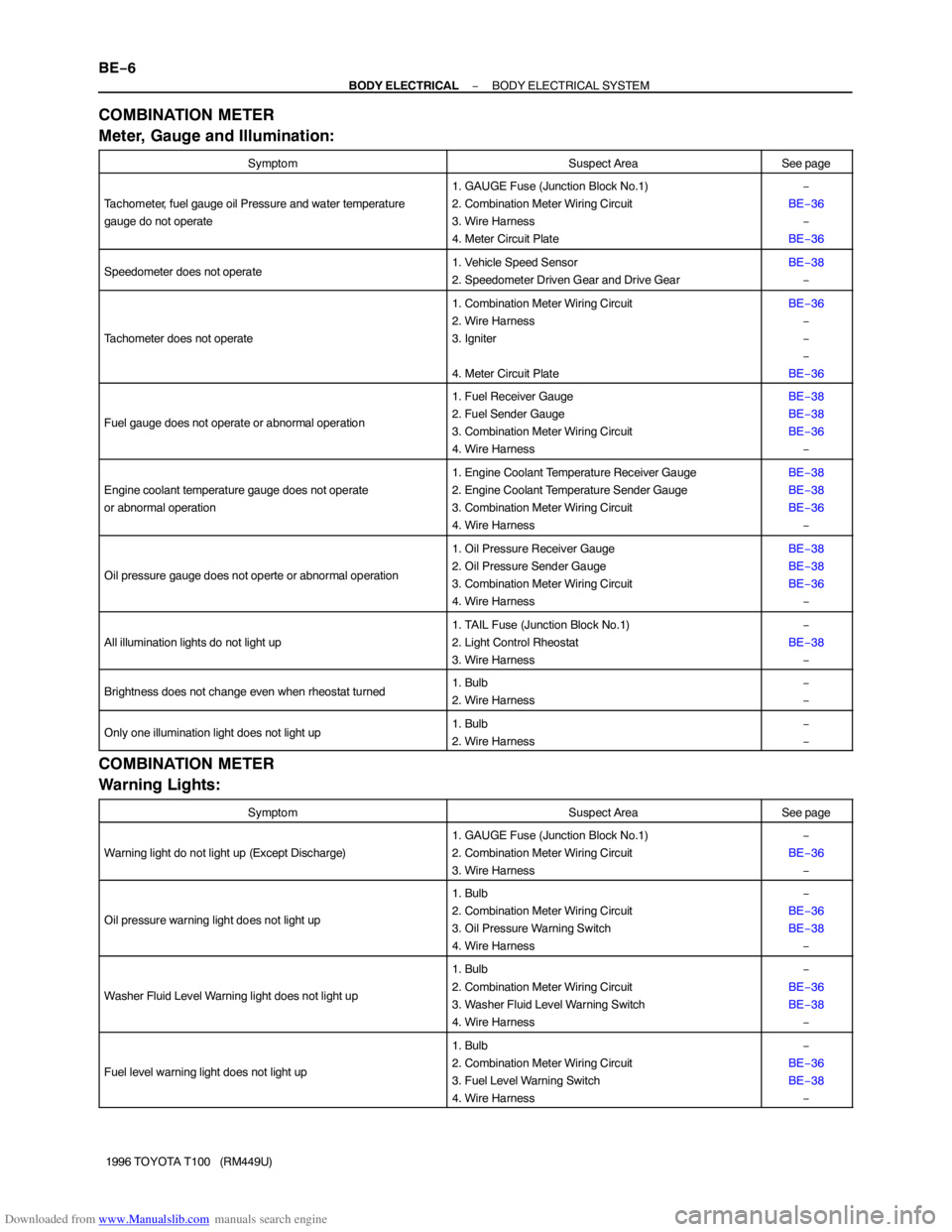
COMBINATION METER
Meter, Gauge and Illumination:
SymptomSuspect AreaSee page
Tachometer, fuel gauge oil Pressure and water temperature
gauge do not operate
1. GAUGE Fuse (Junction Block No.1)
2. Combination Meter Wiring Circuit
3. Wire Harness
4. Meter Circuit Plate−
BE−36
−
BE−36
Speedometer does not operate1. Vehicle Speed Sensor
2. Speedometer Driven Gear and Drive GearBE−38
−
Tachometer does not operate
1. Combination Meter Wiring Circuit
2. Wire Harness
3. Igniter
4. Meter Circuit PlateBE−36
−
−
−
BE−36
Fuel gauge does not operate or abnormal operation
1. Fuel Receiver Gauge
2. Fuel Sender Gauge
3. Combination Meter Wiring Circuit
4. Wire HarnessBE−38
BE−38
BE−36
−
Engine coolant temperature gauge does not operate
or abnormal operation
1. Engine Coolant Temperature Receiver Gauge
2. Engine Coolant Temperature Sender Gauge
3. Combination Meter Wiring Circuit
4. Wire HarnessBE−38
BE−38
BE−36
−
Oil pressure gauge does not operte or abnormal operation
1. Oil Pressure Receiver Gauge
2. Oil Pressure Sender Gauge
3. Combination Meter Wiring Circuit
4. Wire HarnessBE−38
BE−38
BE−36
−
All illumination lights do not light up
1. TAIL Fuse (Junction Block No.1)
2. Light Control Rheostat
3. Wire Harness−
BE−38
−
Brightness does not change even when rheostat turned1. Bulb
2. Wire Harness−
−
Only one illumination light does not light up1. Bulb
2. Wire Harness−
−
COMBINATION METER
Warning Lights:
SymptomSuspect AreaSee page
Warning light do not light up (Except Discharge)
1. GAUGE Fuse (Junction Block No.1)
2. Combination Meter Wiring Circuit
3. Wire Harness−
BE−36
−
Oil pressure warning light does not light up
1. Bulb
2. Combination Meter Wiring Circuit
3. Oil Pressure Warning Switch
4. Wire Harness−
BE−36
BE−38
−
Washer Fluid Level Warning light does not light up
1. Bulb
2. Combination Meter Wiring Circuit
3. Washer Fluid Level Warning Switch
4. Wire Harness−
BE−36
BE−38
−
Fuel level warning light does not light up
1. Bulb
2. Combination Meter Wiring Circuit
3. Fuel Level Warning Switch
4. Wire Harness−
BE−36
BE−38
−
Page 1876 of 2062

Downloaded from www.Manualslib.com manuals search engine N12609
N12610
N06616
Engine Coolant Temperature Gauge
Ignition
Switch
BatterySender
Gauge
N06617
Engine Coolant Temperature Gauge
Test
Bulb
(3.4 W)
− BODY ELECTRICALCOMBINATION METER
BE−41
1996 TOYOTA T100 (RM449U)
10. INSPECT FUEL LEVEL WARNING SWITCH
(a) Apply battery positive voltage between terminal 1 and 3,
and through a 3.4 W test bulb, check the bulb lights up.
HINT:
It will take a short time for bulb to light up.
(b) Submerge the switch in fuel, check that the bulb goes out.
If operation is not as specified, replace the sender gauge.
11. INSPECT ENGINE COOLANT TEMPERATURE RE-
CEIVER GAUGE OPERATION
(a) Disconnect the connector from the sender gauge.
(b) Turn the ignition switch ON, check that the receiver gauge
needle indicates COOL.
(c) Ground terminal on the wire harness side connecter
through a 3.4 W test bulb.
(d) Turn the ignition switch ON, check that the bulb lights up
and the receiver gauge needle moves to the hot side.
If operation is as specified, replace the sender gauge. Then, re-
check the system.
If operation is not as specified, measure the receiver gauge re-
sistance.
Page 1877 of 2062

Downloaded from www.Manualslib.com manuals search engine Z09691
w/ Tachometer
w/o TachometerB
A
C
B A
N02651
Warning Light
Ignition
Switch
Battery
BE0146
BE1222
Oil Pressure Gauge
Ignition
Switch
BatterySender
Gauge BE−42
− BODY ELECTRICALCOMBINATION METER
1996 TOYOTA T100 (RM449U)
12. INSPECT ENGINE COOLANT TEMPERATURE RE-
CEIVER GAUGE RESISTANCE
Measure the resistance between terminals.
w/ Tachometer:
Between terminalsResistance (Ω)
A − BApprox. 150.0
A − CApprox. 54.0
B − CApprox. 138.0
w/o Tachometer:
Between terminalsResistance (Ω)
A − BApprox. 25.0
HINT:
Connect the test leads so that the current from the ohmmeter
can flow according to the above order. This circuit includes the
diode.
If resistance value is not as specified, replace the receiver
gauge.
13. INSPECT OIL PRESSURE WARNING LIGHT
(a) Disconnect the connector from the warning switch and
ground terminal on the wire harness side connector.
(b) Turn the ignition switch ON, check that the warning light
lights up.
If the warning light does not light up, test the bulb.
14. INSPECT OIL PRESSURE SENDER GAUGE
(a) Disconnect the connector from the sender gauge.
(b) Check that there is continuity between terminal and
ground with the engine stopped.
(c) Check that there is no continuity between terminal and
ground with the engine running.
HINT:
Oil pressure should be over 49 kPa (0.5 kgf/cm
2, 7.1 psi).
If operation is not as specified, replace the sender gauge.
15. INSPECT RECEIVER OIL PRESSURE GAUGE OP-
ERATION
(a) Disconnect the connector from the sender gauge.
(b) Turn the ignition switch ON, check that the receiver gauge
needle indicates LOW.
Page 1998 of 2062

Downloaded from www.Manualslib.com manuals search engine AC0FF−02
I01453
N06486
Hose ClipHeater Radiator Pipe
Second ridge Water Hose45 ° Upper
LowerLH
RH
N05820
AC−28
− AIR CONDITIONINGHEATER UNIT
1996 TOYOTA T100 (RM449U)
REMOVAL
1. REMOVE COOLING UNIT (See page AC−23)
2. DRAIN ENGINE COOLANT FROM RADIATOR
HINT:
It is not necessary to drain out all coolant.
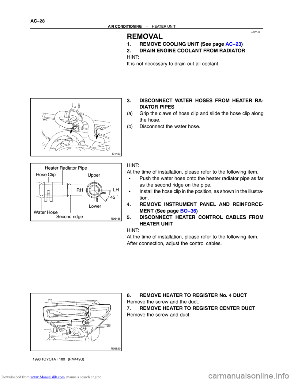
3. DISCONNECT WATER HOSES FROM HEATER RA-
DIATOR PIPES
(a) Grip the claws of hose clip and slide the hose clip along
the hose.
(b) Disconnect the water hose.
HINT:
At the time of installation, please refer to the following item.
�Push the water hose onto the heater radiator pipe as far
as the second ridge on the pipe.
�Install the hose clip in the position, as shown in the illustra-
tion.
4. REMOVE INSTRUMENT PANEL AND REINFORCE-
MENT (See page BO−36)
5. DISCONNECT HEATER CONTROL CABLES FROM
HEATER UNIT
HINT:
At the time of installation, please refer to the following item.
After connection, adjust the control cables.
6. REMOVE HEATER TO REGISTER No. 4 DUCT
Remove the screw and the duct.
7. REMOVE HEATER TO REGISTER CENTER DUCT
Remove the screw and duct.