Page 1031 of 1354
MX02C−02
Q06216
4th Driven Gear3rd Driven GearNeedle Roller Bearing
1st Gear Bearing Inner Race Spacer
Inner Race
2nd Gear
Spacer
Output Shaft Rear Bearing
SpringNo.1 Hub Sleeve
Needle Roller Bearing
1st Gear
Synchronizer Ring
Ball
Output Shaft Front
Bearing
Output Shaft Shifting Key
No.1 Clutch Hub
Synchronizer Ring
� Non−reusable part� MX−36
− MANUAL TRANSAXLEOUTPUT SHAFT
1996 RAV4 (RM447U)
OUTPUT SHAFT
COMPONENTS
Page 1036 of 1354

REASSEMBLY
HINT:
Coat all of the sliding and rotating surfaces with g")
MX02F−04
Q06204
Front
Q06205
SST Align the holes
Z00225
Q06206
SST
− MANUAL TRANSAXLEOUTPUT SHAFT
MX−41
1996 RAV4 (RM447U)
REASSEMBLY
HINT:
Coat all of the sliding and rotating surfaces with gear oil before
reassembly.
1. INSTALL NO.1 CLUTCH HUB INTO HUB SLEEVE
(a) Install the 3 springs and shifting keys to the clutch hub.
(b) Install the hub sleeve to the clutch hub.
HINT:
Direct identification groove of the hub sleeve to the front of the
transmission.
2. INSTALL 1ST GEAR BEARING INNER RACE
Using SST and a press, install the 1st gear bearing inner race.
SST 09506−35010
HINT:
Align the hole of the output shaft and inner race.
3. INSTALL NEEDLE ROLLER BEARING, 1ST GEAR,
SYNCHRONIZER RING AND NO.1 HUB SLEEVE TO
OUTPUT SHAFT
(a) Apply MP grease to the needle roller bearing.
(b) Install the 1st gear.
(c) Place the synchronizer ring (for the 1st gear) on the gear
and align the ring slots with the shifting keys.
(d) Using SST and a press, install the 1st gear and No.1 hub
sleeve.
SST 09316−60011 (09316−00041)
4. MEASURE 1ST GEAR THRUST CLEARANCE
(See page MX−37)
Page 1290 of 1354

INSPECTION
1. INSPECT STEERING LOCK OPERATION
Check that the steering lock mechanism oper")
W01114
SR0F3−03
W01115
ACC
W04213
W04212
SR−16
− STEERINGNON−TILT STEERING COLUMN
1996 RAV4 (RM447U)
INSPECTION
1. INSPECT STEERING LOCK OPERATION
Check that the steering lock mechanism operates properly.
2. IF NECESSARY, REPLACE IGNITION KEY CYLINDER
(a) Place the ignition key at the ACC position.
(b) Using a screwdriver, push down the stop pin of the cylin-
der, and pull it out.
(c) Install a new key cylinder.
HINT:
Make sure that the ignition key is at the ACC position.
3. INSPECT IGNITION SWITCH (See page BE−11)
4. IF NECESSARY, REPLACE IGNITION SWITCH
(a) Remove the 2 screws.
(b) Install a new switch with the 2 screws.
5. INSPECT KEY UNLOCK WARNING SWITCH
(See page BE−11)
6. IF NECESSARY, REPLACE KEY UNLOCK WARNING
SWITCH
(a) Remove the 2 screws.
(b) Install a new switch with the 2 screws.
7. IF NECESSARY, REPLACE STEERING MAIN SHAFT
BUSHING
(a) Using a screwdriver, loosen the 3 projections of the bush-
ing, and remove the bushing from the steering column
tube.
(b) Coat the inside of a new bushing with molybdenum disul-
fide lithium base grease.
(c) Align the projections on the bushing with the holes in the
column tube, then install the bushing until the projections
are firmly engaged in the holes.
Page 1306 of 1354
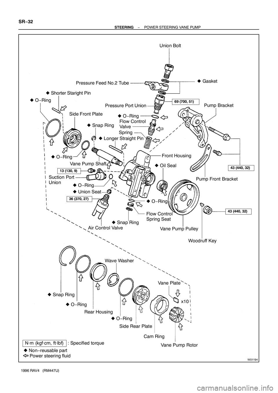
W01194
N·m (kgf·cm, ft·lbf) : Specified torque
� Non−reusable partUnion Bolt
Spring Pressure Feed No.2 Tube
Side Front PlatePressure Port Union
Flow Control
Valve
Pump Front Bracket
Flow Control
Spring Seat� Gasket
� Shorter Staright Pin
Air Control Valve � O−Ring
� Snap Ring� O−Ring
� Union Seat� Longer Straight Pin
Vane Pump Shaft
Suction Port
UnionFront Housing
� O−Ring
� Oil Seal
� O−Ring
� O−Ring
Woodruff Key Vane Pump PulleyPump Bracket
� Snap Ring
Cam Ring Side Rear PlateVane Plate Wave Washer
Vane Pump Rotorx10
Power steering fluidRear Housing
� O−Ring � O−Ring � Snap Ring
69 (700, 51)
13 (130, 9)43 (440, 32)
36 (370, 27)
43 (440, 32)
SR−32
− STEERINGPOWER STEERING VANE PUMP
1996 RAV4 (RM447U)
Page 1308 of 1354

DISASSEMBLY
NOTICE:
When using a vise, do not overtighten it.
1. MEASURE PS VANE PUMP ROTATING TOR")
SR0FX−03
R10967
R10992
SST
R10968
SR−34
− STEERINGPOWER STEERING VANE PUMP
1996 RAV4 (RM447U)
DISASSEMBLY
NOTICE:
When using a vise, do not overtighten it.
1. MEASURE PS VANE PUMP ROTATING TORQUE
(a) Check that the pump rotates smoothly without abnormal
noise.
(b) Using a torque wrench, check the pump rotating torque.
Rotating torque:
0.3 N·m (2.8 kgf·cm, 2.4 in.·lbf) or less
2. REMOVE PUMP FRONT BRACKET AND PUMP
BRACKET
Remove the 2 bolts.
3. REMOVE VANE PUMP PULLEY
(a) Using SST to stop the pulley rotating, remove the pulley
set nut.
SST 09960−10010 (09962−01000, 09963−01000)
(b) Remove the woodruff key from the vane pump shaft.
4. REMOVE AIR CONTROL VALVE
Remove the union seat.
5. REMOVE PRESSURE FEED NO.2 TUBE
Remove the union bolt and 2 gaskets.
6. REMOVE SUCTION PORT UNION
(a) Remove the union set bolt.
(b) Remove the O−ring from the union.
7. REMOVE PRESSURE PORT UNION
Remove the O−ring from the union.
8. REMOVE FLOW CONTROL VALVE AND SPRING
9. REMOVE FLOW CONTROL SPRING SEAT
(a) Using snap ring pliers, remove the snap ring.
(b) Install the 2 or 3 threads of a bolt (6 mm normal diameter,
1.0 mm pitch, 50 mm length).
Reference
Bolt: 91651−60650
(c) Using pliers, remove the spring seat from the front hous-
ing.
(d) Remove the O−ring from the flow control spring seat.
Page 1315 of 1354

(d) Using snap ring pliers, install a new snap ring.
12. INSTALL SPRING AND FLOW CONTROL VALVE
Install the val")
R10995
2.5°
R10992
SST
− STEERINGPOWER STEERING VANE PUMP
SR−41
1996 RAV4 (RM447U)
(d) Using snap ring pliers, install a new snap ring.
12. INSTALL SPRING AND FLOW CONTROL VALVE
Install the valve facing the correct direction
(See page SR−31).
13. INSTALL PRESSURE PORT UNION
(a) Coat a new O−ring with power steering fluid and install it
to the union.
(b) Torque the union.
Torque: 69 N·m (700 kgf·cm, 51 ft·lbf)
14. INSTALL SUCTION PORT UNION
(a) Coat a new O−ring with power steering fluid and install it
to the union.
(b) Install the O−ring to the union.
(c) Install the union with the bolt.
Torque: 13 N·m (130 kgf·cm, 9 ft·lbf)
15. INSTALL PRESSURE FEED NO.2 TUBE
Torque the union bolt with a new gasket on each side of the
tube.
Torque: 69 N·m (700 kgf·cm, 51 ft·lbf)
HINT:
Pressure feed No.2 tube installation angle is 2.5°.
16. INSTALL AIR CONTROL VALVE
(a) Install a new union seat.
(b) Torque the valve.
Torque: 36 N·m (370 kgf·cm, 27 ft·lbf)
17. INSTALL VANE PUMP PULLEY
(a) Install the woodruff key to the vane pump shaft.
(b) Using SST to stop the pulley rotating, torque the nut.
SST 09960−10010
Torque: 43 N·m (440 kgf·cm, 32 ft·lbf)
18. INSTALL PUMP BRACKET AND PUMP FRONT
BRACKET
Temporarily tighten the 2 bolts.
19. MEASURE PS VANE PUMP ROTATING TORQUE
(See page SR−34)