Page 728 of 1354
S01560
(1)
(2)
(3)
P15451
ConnectNew
New
Gasket
O−Ring
S01594
S01368
EM−62
− ENGINE MECHANICALCYLINDER HEAD
1996 RAV4 (RM447U)
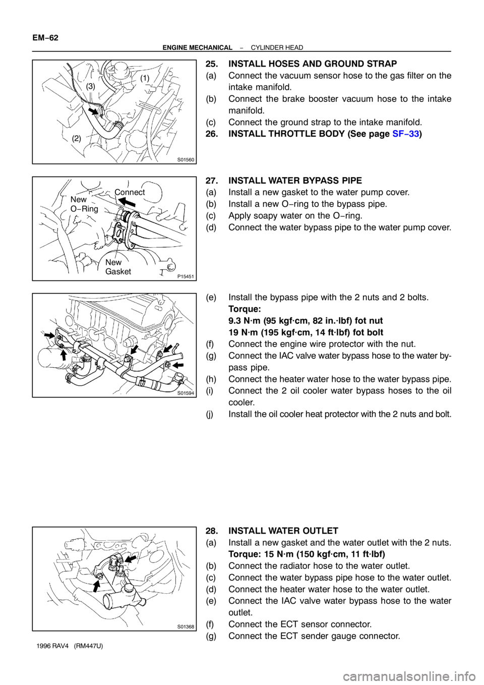
25. INSTALL HOSES AND GROUND STRAP
(a) Connect the vacuum sensor hose to the gas filter on the
intake manifold.
(b) Connect the brake booster vacuum hose to the intake
manifold.
(c) Connect the ground strap to the intake manifold.
26. INSTALL THROTTLE BODY (See page SF−33)
27. INSTALL WATER BYPASS PIPE
(a) Install a new gasket to the water pump cover.
(b) Install a new O−ring to the bypass pipe.
(c) Apply soapy water on the O−ring.
(d) Connect the water bypass pipe to the water pump cover.
(e) Install the bypass pipe with the 2 nuts and 2 bolts.
Torque:
9.3 N·m (95 kgf·cm, 82 in.·lbf) fot nut
19 N·m (195 kgf·cm, 14 ft·lbf) fot bolt
(f) Connect the engine wire protector with the nut.
(g) Connect the IAC valve water bypass hose to the water by-
pass pipe.
(h) Connect the heater water hose to the water bypass pipe.
(i) Connect the 2 oil cooler water bypass hoses to the oil
cooler.
(j) Install the oil cooler heat protector with the 2 nuts and bolt.
28. INSTALL WATER OUTLET
(a) Install a new gasket and the water outlet with the 2 nuts.
Torque: 15 N·m (150 kgf·cm, 11 ft·lbf)
(b) Connect the radiator hose to the water outlet.
(c) Connect the water bypass pipe hose to the water outlet.
(d) Connect the heater water hose to the water outlet.
(e) Connect the IAC valve water bypass hose to the water
outlet.
(f) Connect the ECT sensor connector.
(g) Connect the ECT sender gauge connector.
Page 731 of 1354
EM0EV−02
A04063
N·m (kgf·cm, ft·lbf) : Specified torque
� Non−reusable part
29 (300, 22)
Hold Down ClampHold Down Clamp
BatteryEngine Hood
Battery Tray
Lower Radiator
HosePS Pump
w/ BracketCharcoal Canister
Battery Tray
IAT Sensor ConnectorAir Cleaner Cap
� Gasket
� Gasket
Fuel Inlet Hose
Fuel Filter
Water Inlet
Upper Radiator
Hose
Heater Hose
PS Pump Drive Belt
Generator Drive
Belt
Accelerator Cable
Generator
Generator Drive Belt
Adjusting Bar
Air Filter
EVAP VSV Connector
Air Cleaner Case
Radiator
Reservoir
Relay Block No. 2
Upper Cover
Relay Block No. 2
Wire Harness
A/C Compressor
Type B Type A
Type B Type A
− ENGINE MECHANICALENGINE UNIT
EM−65
1996 RAV4 (RM447U)
ENGINE UNIT
COMPONENTS
Page 734 of 1354
EM1BA−02
S01374
Cover
Connector EM−68
− ENGINE MECHANICALENGINE UNIT
1996 RAV4 (RM447U)
REMOVAL
1. REMOVE BATTERY
2. REMOVE ENGINE HOOD
3. REMOVE ENGINE UNDER COVERS
4. DRAIN ENGINE COOLANT
5. DRAIN ENGINE OIL
6. DRAIN TRANSAXLE OIL
7. REMOVE AIR CLEANER CAP AND CASE
8. DISCONNECT ACCELERATOR CABLE FROM
THROTTLE BODY, CABLE BRACKET AND CLAMPS
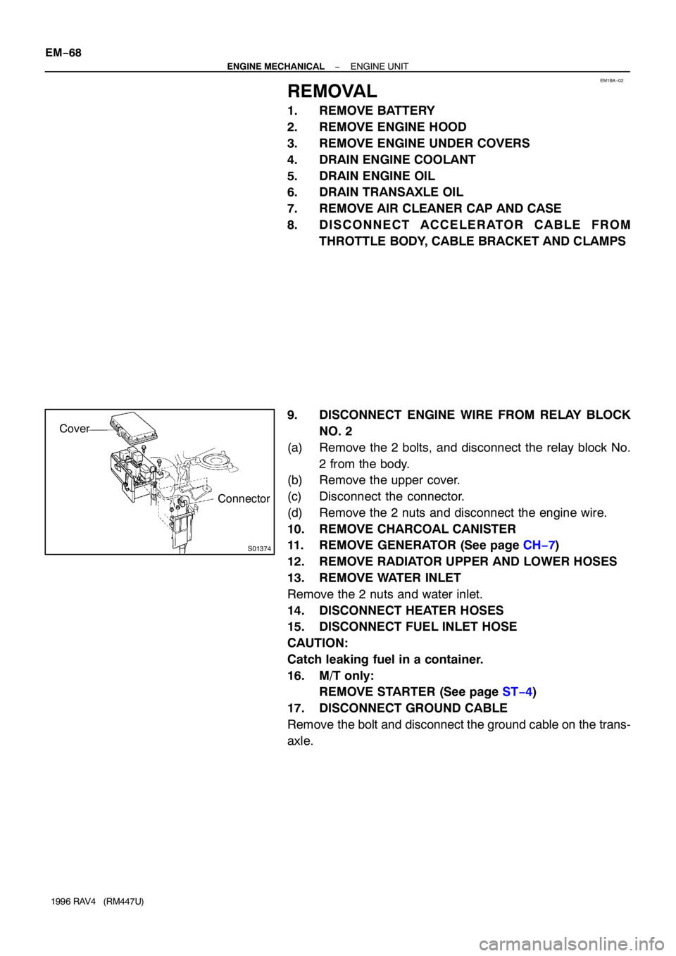
9. DISCONNECT ENGINE WIRE FROM RELAY BLOCK
NO. 2
(a) Remove the 2 bolts, and disconnect the relay block No.
2 from the body.
(b) Remove the upper cover.
(c) Disconnect the connector.
(d) Remove the 2 nuts and disconnect the engine wire.
10. REMOVE CHARCOAL CANISTER
11. REMOVE GENERATOR (See page CH−7)
12. REMOVE RADIATOR UPPER AND LOWER HOSES
13. REMOVE WATER INLET
Remove the 2 nuts and water inlet.
14. DISCONNECT HEATER HOSES
15. DISCONNECT FUEL INLET HOSE
CAUTION:
Catch leaking fuel in a container.
16. M/T only:
REMOVE STARTER (See page ST−4)
17. DISCONNECT GROUND CABLE
Remove the bolt and disconnect the ground cable on the trans-
axle.
Page 744 of 1354
S01797
M/T
A/T
S01785
A/T Only
S01351
M/T Only
Back−up Light
Connector EM−78
− ENGINE MECHANICALENGINE UNIT
1996 RAV4 (RM447U)
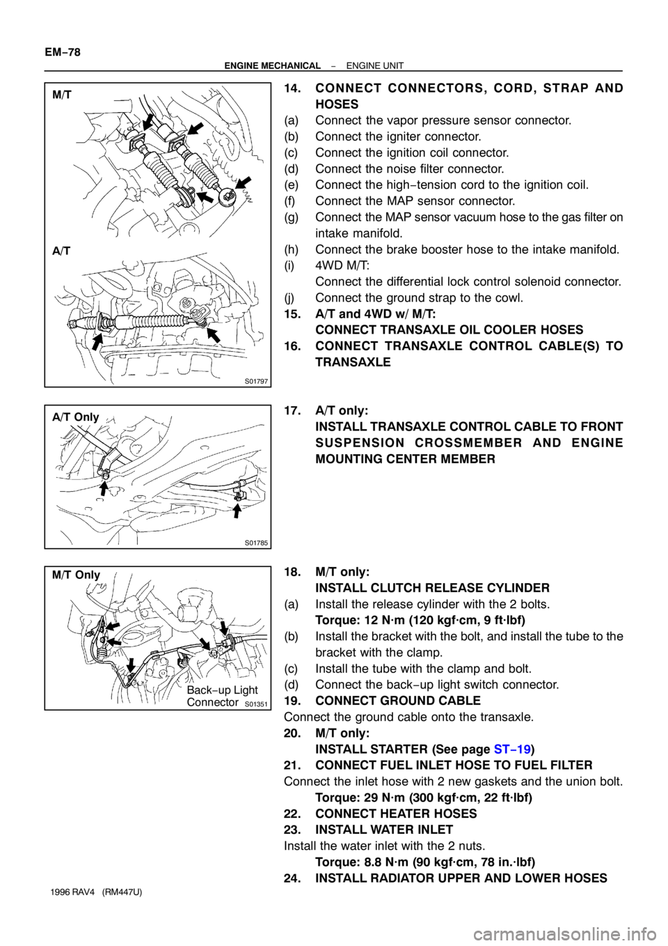
14. CONNECT CONNECTORS, CORD, STRAP AND
HOSES
(a) Connect the vapor pressure sensor connector.
(b) Connect the igniter connector.
(c) Connect the ignition coil connector.
(d) Connect the noise filter connector.
(e) Connect the high−tension cord to the ignition coil.
(f) Connect the MAP sensor connector.
(g) Connect the MAP sensor vacuum hose to the gas filter on
intake manifold.
(h) Connect the brake booster hose to the intake manifold.
(i) 4WD M/T:
Connect the differential lock control solenoid connector.
(j) Connect the ground strap to the cowl.
15. A/T and 4WD w/ M/T:
CONNECT TRANSAXLE OIL COOLER HOSES
16. CONNECT TRANSAXLE CONTROL CABLE(S) TO
TRANSAXLE
17. A/T only:
INSTALL TRANSAXLE CONTROL CABLE TO FRONT
SUSPENSION CROSSMEMBER AND ENGINE
MOUNTING CENTER MEMBER
18. M/T only:
INSTALL CLUTCH RELEASE CYLINDER
(a) Install the release cylinder with the 2 bolts.
Torque: 12 N·m (120 kgf·cm, 9 ft·lbf)
(b) Install the bracket with the bolt, and install the tube to the
bracket with the clamp.
(c) Install the tube with the clamp and bolt.
(d) Connect the back−up light switch connector.
19. CONNECT GROUND CABLE
Connect the ground cable onto the transaxle.
20. M/T only:
INSTALL STARTER (See page ST−19)
21. CONNECT FUEL INLET HOSE TO FUEL FILTER
Connect the inlet hose with 2 new gaskets and the union bolt.
Torque: 29 N·m (300 kgf·cm, 22 ft·lbf)
22. CONNECT HEATER HOSES
23. INSTALL WATER INLET
Install the water inlet with the 2 nuts.
Torque: 8.8 N·m (90 kgf·cm, 78 in.·lbf)
24. INSTALL RADIATOR UPPER AND LOWER HOSES
Page 799 of 1354
29
G
Position of Parts in Engine Compartment
I 1 Idle Air Control Valve R 1Radiator Fan Motor
I 2 Igniter R 2 Rear Washer Motor
I 3 Ignition Coil and Distributor
I 4 Ignition Coil and Distributor S 1 Solenoid Valve SLD
I 5 Injector No. 1 S 2 Starter
I 6 Injector No. 2 S 3 Starter
I 7 Injector No. 3
I 8 Injector No. 4 T 1 Throttle Position Sensor
I 9 Intake Air Temp. Sensor
V 1 Vapor Pressure Sensor
K 1 Knock Sensor V 2 Vehicle Speed Sensor (Combination Meter)
V 3 Vehicle Speed Sensor (Front)
M 1 Manifold Absolute Pressure Sensor V 4 Vehicle Speed Sensor (Rear)
V 5 VSV (Center Diff. Lock No. 1)
N 1 Noise Filter (Ignition System) V 6 VSV (Center Diff. Lock No. 2)
V 7 VSV (EGR)
O 1 Oil Pressure SW V 8 VSV (EVAP)
O 2 Oxygen Sensor (Bank 1 Sensor 1) V 9 VSV (Vapor Pressure Sensor)
O 3 Oxygen Sensor (Bank 1 Sensor 2)
W 1 Water Temp. Sender
P 1 Park/Neutral Position SW (A/T)
Page 828 of 1354
12
X
X78A A A A A
AAAA AAAA A A
CCC
X23
XX
56
X C 8 F 7 I10 J 1
BLUEJ 5
BLACK
BGRAY P 1 (
4WD)
AGRAY P 1 (
2WD)(
HINT : SEE PAGE 7) (
HINT : SEE PAGE 7) (
SEE PAGE 25)
X1
1 ABLACK S 3
B S 2
59
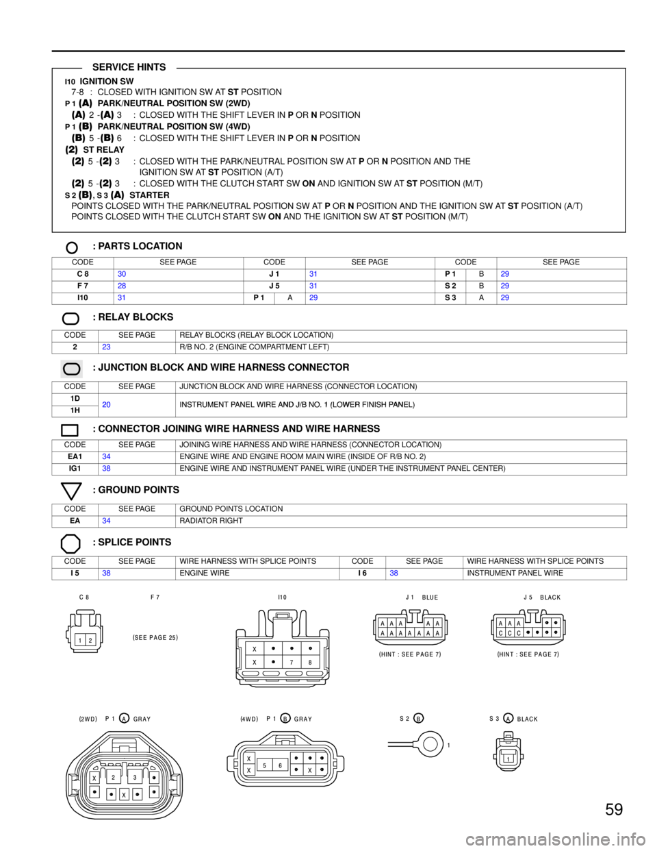
I10 IGNITION SW
7-8 : CLOSED WITH IGNITION SW AT ST POSITION
P 1 (A) PARK/NEUTRAL POSITION SW (2WD)
(A) 2 -(A) 3 : CLOSED WITH THE SHIFT LEVER IN P OR N POSITION
P 1 (B) PARK/NEUTRAL POSITION SW (4WD)
(B) 5 -(B) 6 : CLOSED WITH THE SHIFT LEVER IN P OR N POSITION
(2) ST RELAY
(2) 5 -(2) 3 : CLOSED WITH THE PARK/NEUTRAL POSITION SW AT P OR N POSITION AND THE
IGNITION SW AT ST POSITION (A/T)
(2) 5 -(2) 3 : CLOSED WITH THE CLUTCH START SW ON AND IGNITION SW AT ST POSITION (M/T)
S 2 (B), S 3 (A) STARTER
POINTS CLOSED WITH THE PARK/NEUTRAL POSITION SW AT P OR N POSITION AND THE IGNITION SW AT ST POSITION (A/T)
POINTS CLOSED WITH THE CLUTCH START SW ON AND THE IGNITION SW AT ST POSITION (M/T)
: PARTS LOCATION
CODESEE PAGECODESEE PAGECODESEE PAGE
C 830J 131P 1B29
F 728J 531S 2B29
I1031P 1A29S 3A29
: RELAY BLOCKS
CODESEE PAGERELAY BLOCKS (RELAY BLOCK LOCATION)
223R/B NO. 2 (ENGINE COMPARTMENT LEFT)
: JUNCTION BLOCK AND WIRE HARNESS CONNECTOR
CODESEE PAGEJUNCTION BLOCK AND WIRE HARNESS (CONNECTOR LOCATION)
1D20INSTRUMENT PANEL WIRE AND J/B NO 1 (LOWER FINISH PANEL)1H20INSTRUMENT PANEL WIRE AND J/B NO. 1 (LOWER FINISH PANEL)
: CONNECTOR JOINING WIRE HARNESS AND WIRE HARNESS
CODESEE PAGEJOINING WIRE HARNESS AND WIRE HARNESS (CONNECTOR LOCATION)
EA134ENGINE WIRE AND ENGINE ROOM MAIN WIRE (INSIDE OF R/B NO. 2)
IG138ENGINE WIRE AND INSTRUMENT PANEL WIRE (UNDER THE INSTRUMENT PANEL CENTER)
: GROUND POINTS
CODESEE PAGEGROUND POINTS LOCATION
EA34RADIATOR RIGHT
: SPLICE POINTS
CODESEE PAGEWIRE HARNESS WITH SPLICE POINTSCODESEE PAGEWIRE HARNESS WITH SPLICE POINTS
I 538ENGINE WIREI 638INSTRUMENT PANEL WIRE
SERVICE HINTS
Page 841 of 1354
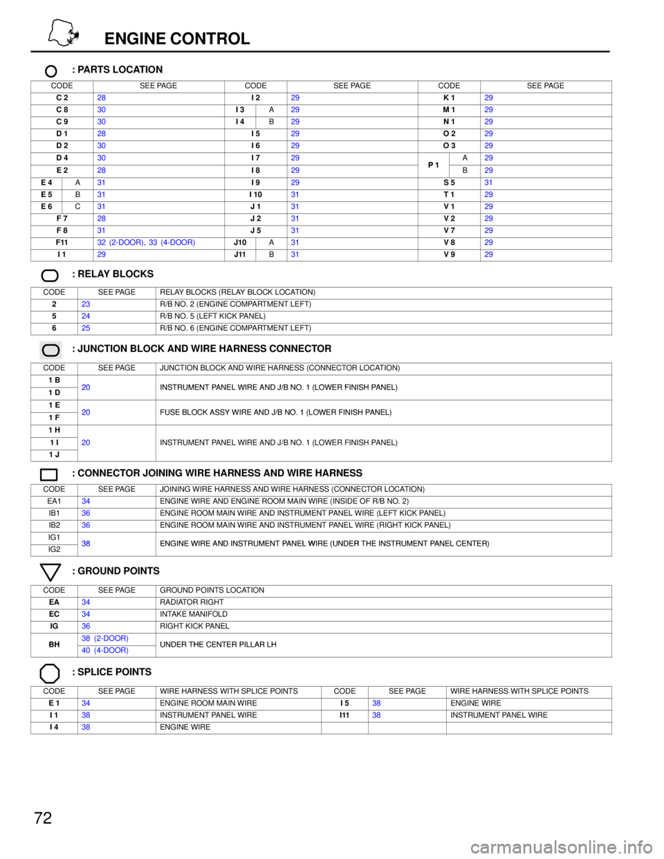
72
ENGINE CONTROL
: PARTS LOCATION
CODESEE PAGECODESEE PAGECODESEE PAGE
C 228I 229K 129
C 830I 3A29M 129
C 930I 4B29N 129
D 128I 529O 229
D 230I 629O 329
D 430I 729P1A29
E 228I 829P 1B29
E 4A31I 929S 531
E 5B31I 1031T 129
E 6C31J 131V 129
F 728J 231V 229
F 831J 531V 729
F1132 (2-DOOR), 33 (4-DOOR)J10A31V 829
I 129J11B31V 929
: RELAY BLOCKS
CODESEE PAGERELAY BLOCKS (RELAY BLOCK LOCATION)
223R/B NO. 2 (ENGINE COMPARTMENT LEFT)
524R/B NO. 5 (LEFT KICK PANEL)
625R/B NO. 6 (ENGINE COMPARTMENT LEFT)
: JUNCTION BLOCK AND WIRE HARNESS CONNECTOR
CODESEE PAGEJUNCTION BLOCK AND WIRE HARNESS (CONNECTOR LOCATION)
1 B20INSTRUMENT PANEL WIRE AND J/B NO 1 (LOWER FINISH PANEL)1 D20INSTRUMENT PANEL WIRE AND J/B NO. 1 (LOWER FINISH PANEL)
1 E20FUSE BLOCK ASSY WIRE AND J/B NO 1 (LOWER FINISH PANEL)1 F20FUSE BLOCK ASSY WIRE AND J/B NO. 1 (LOWER FINISH PANEL)
1 H
1 I20INSTRUMENT PANEL WIRE AND J/B NO. 1 (LOWER FINISH PANEL)
1 J
()
: CONNECTOR JOINING WIRE HARNESS AND WIRE HARNESS
CODESEE PAGEJOINING WIRE HARNESS AND WIRE HARNESS (CONNECTOR LOCATION)
EA134ENGINE WIRE AND ENGINE ROOM MAIN WIRE (INSIDE OF R/B NO. 2)
IB136ENGINE ROOM MAIN WIRE AND INSTRUMENT PANEL WIRE (LEFT KICK PANEL)
IB236ENGINE ROOM MAIN WIRE AND INSTRUMENT PANEL WIRE (RIGHT KICK PANEL)
IG138ENGINE WIRE AND INSTRUMENT PANEL WIRE (UNDER THE INSTRUMENT PANEL CENTER)IG238ENGINE WIRE AND INSTRUMENT PANEL WIRE (UNDER THE INSTRUMENT PA N E L CENTER)
: GROUND POINTS
CODESEE PAGEGROUND POINTS LOCATION
EA34RADIATOR RIGHT
EC34INTAKE MANIFOLD
IG36RIGHT KICK PANEL
BH38 (2-DOOR)UNDER THE CENTER PILLAR LHBH40 (4-DOOR)UNDER THE CENTER PILLAR LH
: SPLICE POINTS
CODESEE PAGEWIRE HARNESS WITH SPLICE POINTSCODESEE PAGEWIRE HARNESS WITH SPLICE POINTS
E 134ENGINE ROOM MAIN WIREI 538ENGINE WIRE
I 138INSTRUMENT PANEL WIREI1138INSTRUMENT PANEL WIRE
I 438ENGINE WIRE
Page 852 of 1354
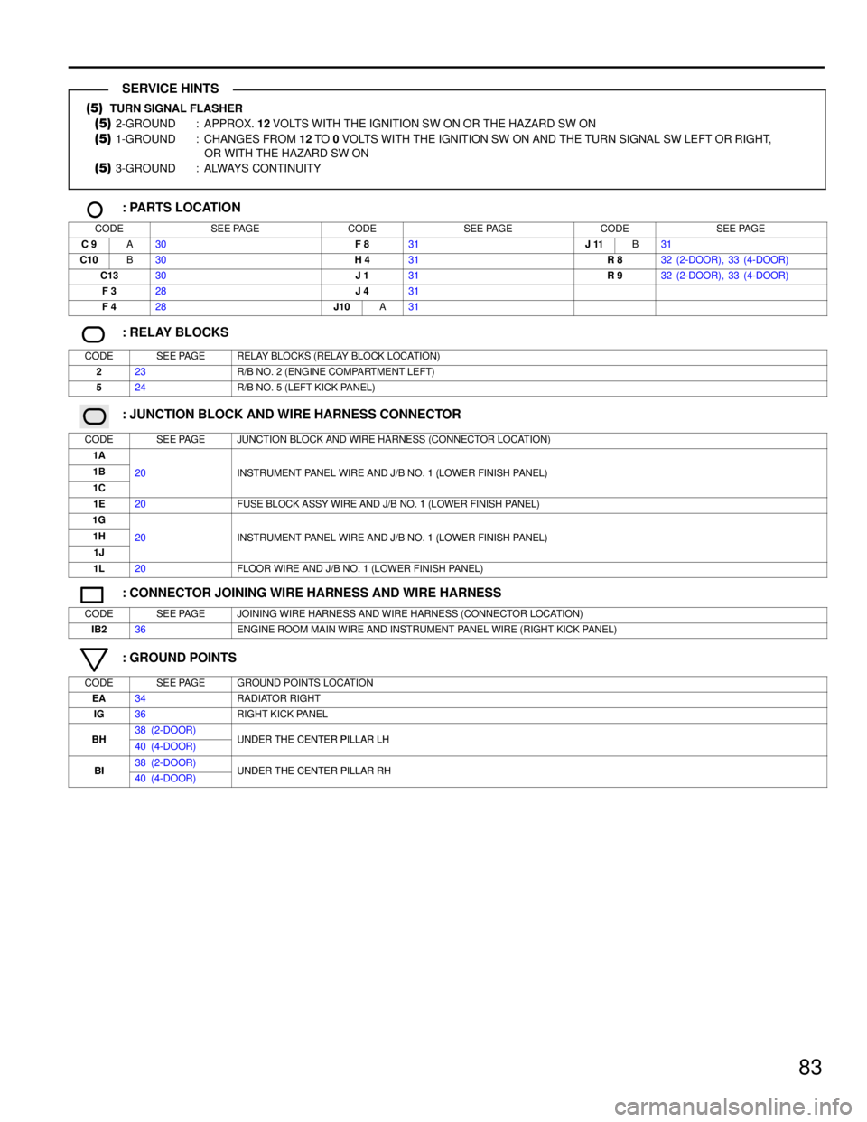
83
(5) TURN SIGNAL FLASHER
(5) 2-GROUND : APPROX. 12 VOLTS WITH THE IGNITION SW ON OR THE HAZARD SW ON
(5) 1-GROUND : CHANGES FROM 12 TO 0 VOLTS WITH THE IGNITION SW ON AND THE TURN SIGNAL SW LEFT OR RIGHT,
OR WITH THE HAZARD SW ON
(5) 3-GROUND : ALWAYS CONTINUITY
: PARTS LOCATION
CODESEE PAGECODESEE PAGECODESEE PAGE
C 9A30F 831J 11B31
C10B30H 431R 832 (2-DOOR), 33 (4-DOOR)
C1330J 131R 932 (2-DOOR), 33 (4-DOOR)
F 328J 431
F 428J10A31
: RELAY BLOCKS
CODESEE PAGERELAY BLOCKS (RELAY BLOCK LOCATION)
223R/B NO. 2 (ENGINE COMPARTMENT LEFT)
524R/B NO. 5 (LEFT KICK PANEL)
: JUNCTION BLOCK AND WIRE HARNESS CONNECTOR
CODESEE PAGEJUNCTION BLOCK AND WIRE HARNESS (CONNECTOR LOCATION)
1A
1B20INSTRUMENT PANEL WIRE AND J/B NO. 1 (LOWER FINISH PANEL)
1C
20INSTRUMENT PANEL WIRE AND J/B NO. 1 (LOWER FINISH PANEL)
1E20FUSE BLOCK ASSY WIRE AND J/B NO. 1 (LOWER FINISH PANEL)
1G
1H20INSTRUMENT PANEL WIRE AND J/B NO. 1 (LOWER FINISH PANEL)
1J
20INSTRUMENT PANEL WIRE AND J/B NO. 1 (LOWER FINISH PANEL)
1L20FLOOR WIRE AND J/B NO. 1 (LOWER FINISH PANEL)
: CONNECTOR JOINING WIRE HARNESS AND WIRE HARNESS
CODESEE PAGEJOINING WIRE HARNESS AND WIRE HARNESS (CONNECTOR LOCATION)
IB236ENGINE ROOM MAIN WIRE AND INSTRUMENT PANEL WIRE (RIGHT KICK PANEL)
: GROUND POINTS
CODESEE PAGEGROUND POINTS LOCATION
EA34RADIATOR RIGHT
IG36RIGHT KICK PANEL
BH38 (2-DOOR)UNDER THE CENTER PILLAR LHBH40 (4-DOOR)UNDER THE CENTER PILLAR LH
BI38 (2-DOOR)UNDER THE CENTER PILLAR RHBI40 (4-DOOR)UNDER THE CENTER PILLAR RH
SERVICE HINTS