Page 1004 of 1354

MX−9
1996 RAV4 (RM447U)
REMOVAL
1. REMOVE TRANSAXLE WITH ENGINE
(See page EM−80)
2. R")
MX05S−01
Q09031
B
A
C
FED A
A
C
Q08759
No.1
No.2 No.0
No.0
− MANUAL TRANSAXLEMANUAL TRANSAXLE UNIT (4WD)
MX−9
1996 RAV4 (RM447U)
REMOVAL
1. REMOVE TRANSAXLE WITH ENGINE
(See page EM−80)
2. REMOVE TRANSAXLE CASE PROTECTOR
Remove the 2 bolts and transaxle case protector.
Torque: 25 N·m (250 kgf·cm, 18 ft·lbf)
3. REMOVE STARTER
(a) Disconnect the connector and wire from the starter.
(b) Remove the 2 bolts and starter.
Torque: 39 N·m (400 kgf·cm, 29 ft·lbf)
4. DISCONNECT DIFFERENTIAL LOCK INDICATOR
SWITCH, BACK−UP LIGHT SWITCH AND VEHICLE
SPEED SENSOR CONNECTORS
5. REMOVE TRANSFER VACUUM ACTUATOR BRACK-
ET
Remove the 4 bolts and bracket.
Torque: 37 N·m (380 kgf·cm, 27 ft·lbf)
6. REMOVE TRANSFER VACUUM ACTUATOR AS-
SEMBLY
(a) Disconnect the 4 solenoid hoses from the transfer vacu-
um actuator assembly.
NOTICE:
At the time of installation, please refer to the following item.
Check that the hose No.0, No.1 and No.2 are securely
installed to the solenoid.
(b) Remove the 2 bolts and transfer vacuum actuator assem-
bly.
Torque: 37 N·m (380 kgf·cm, 27 ft·lbf)
7. REMOVE RIGHT TRANSFER STIFFENER PLATE
Remove the 5 bolts and right transfer stiffener plate.
Torque: 37 N·m (380 kgf·cm, 27 ft·lbf)
8. REMOVE CENTER TRANSFER STIFFENER PLATE
Remove the 3 bolts and center transfer stiffener plate.
Torque: 37 N·m (380 kgf·cm, 27 ft·lbf)
9. REMOVE STIFFENER PLATE
Remove the 2 bolts and stiffener plate.
Torque: 37 N·m (380 kgf·cm, 27 ft·lbf)
10. REMOVE TRANSAXLE FROM ENGINE
(a) Remove the 9 transaxle mounting bolts from the engine.
Torque:
Bolt A: 64 N·m (650 kgf·cm, 47 ft·lbf)
Bolt B: 35 N·m (360 kgf·cm, 26 ft·lbf)
Bolt C: 29 N·m (300 kgf·cm, 22 ft·lbf)
Bolt D: 46 N·m (470 kgf·cm, 34 ft·lbf)
Bolt E: 25 N·m (250 kgf·cm, 18 ft·lbf)
Bolt F: 9.0 N·m (95 kgf·cm, 78 in.·lbf)
Page 1005 of 1354
Q06187
Q06188
Q06189
MX−10
− MANUAL TRANSAXLEMANUAL TRANSAXLE UNIT (4WD)
1996 RAV4 (RM447U)
(b) Pull straight until there is a gap of about 60−80 mm
(2.4−3.1 in.) between the engine and transaxle case.
(c) Move the transmission case cover in the direction, as
shown in the illustration.
(d) While holding transfer output, gently pull out whole trans-
axle.
Page 1008 of 1354
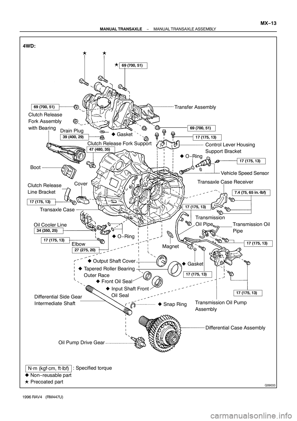
Q09033
Clutch Release
Fork Assembly
with Bearing
Clutch Release Fork Support
Control Lever Housing
Support Bracket
Boot� O−Ring
Cover
Clutch Release
Line Bracket
Transaxle Case
Elbow� O−RingVehicle Speed Sensor
Transaxle Case Receiver
Transmission Oil
Pipe
Magnet
� Output Shaft Cover
� Tapered Roller Bearing
Outer Race
� Front Oil Seal
� Input Shaft Front
Oil Seal
Transmission Oil Pump
Assembly
Differential Case Assembly
Oil Pump Drive Gear
34 (350, 25)
27 (275, 20)
7.4 (75, 65 in.·lbf)
17 (175, 13)
17 (175, 13)
17 (175, 13)
17 (175, 13)
17 (175, 13)
17 (175, 13)
N·m (kgf·cm, ft·lbf): Specified torque
� Non−reusable part
� Precoated part 4WD:
�
�
Transfer Assembly
Transmission
Oil Pipe
17 (175, 13)
17 (175, 13)
69 (700, 51)
69 (700, 51)
39 (400, 29)
47 (480, 35)
Differential Side Gear
Intermediate Shaft
� Snap Ring
69 (700, 51)
Drain Plug
Oil Cooler Line� Gasket
� Gasket �
− MANUAL TRANSAXLEMANUAL TRANSAXLE ASSEMBLY
MX−13
1996 RAV4 (RM447U)
Page 1011 of 1354

DISASSEMBLY
1. 4WD:
REMOVE TRANSFER ASSEMBLY
(a) Remove the 3 bolts.
Sealant")
MX05V−02
Q08757
FIPG
Z12375SST
Q09043
255.5 mm MX−16
− MANUAL TRANSAXLEMANUAL TRANSAXLE ASSEMBLY
1996 RAV4 (RM447U)
DISASSEMBLY
1. 4WD:
REMOVE TRANSFER ASSEMBLY
(a) Remove the 3 bolts.
Sealant:
Part No. 08833−00080, THREE BOND 1344, LOCTITE
242 or equivalent
Torque: 69 N·m (700 kgf·cm, 51 ft·lbf)
(b) Remove the 5 nuts.
Torque: 69 N·m (700 kgf·cm, 51 ft·lbf)
(c) Using a plastic hammer, remove the transfer assembly
from the transaxle.
HINT:
At the time of reassembly, please refer to the following item.
Shift into the 4th gear, and install the transfer assembly while
turning the input shaft of the transaxle.
FIPG:
Part No. 08826−00090, THREE BOND 1281 or equiva-
lent
2. 4WD:
REMOVE DIFFERENTIAL SIDE GEAR INTERMEDI-
ATE SHAFT
(a) Screw in a suitable bolt with a washer into the side gear
intermediate shaft.
(b) Using SST, remove the side gear intermediate shaft.
SST 09910−00015 (09911−00011, 09912−00010)
(c) Remove the snap ring from the differential side gear inter-
mediate shaft.
HINT:
At the time of reassembly, please refer to the following item.
Keeping the intermediate shaft on the differential pinion shaft,
measure the dimension, as shown in the illustration.
Protrusion length: 255.5 mm (10.06 in.)
3. REMOVE RELEASE FORK AND BEARING
4. REMOVE BACK−UP LIGHT SWITCH WITH GASKET
Torque: 40 N·m (410 kgf·cm, 30 ft·lbf)
5. REMOVE BOLT AND VEHICLE SPEED SENSOR
Torque: 17 N·m (175 kgf·cm, 13 ft·lbf)
6. REMOVE NO.2 SELECTING BELLCRANK WITH SE-
LECTING BELLCRANK SUPPORT
Remove the 2 bolts and No.2 selecting bellcrank with the se-
lecting bellcrank support.
Sealant:
Part No. 08833−00080, THREE BOND 1344, LOCTITE
242 or equivalent
Torque: 20 N·m (200 kgf·cm, 14 ft·lbf)
Page 1070 of 1354

MX−75
1996 RAV4 (RM447U)
3. INSPECT DIFFERENTIAL LOCK CONTROL SOLE-
NOID
Inspect the differential lock control solenoid.
(1) Disconnect the co")
− MANUAL TRANSAXLEDIFFERENTIAL LOCKING SYSTEM (4WD)
MX−75
1996 RAV4 (RM447U)
3. INSPECT DIFFERENTIAL LOCK CONTROL SOLE-
NOID
Inspect the differential lock control solenoid.
(1) Disconnect the connector from the solenoid No.1
and No.2.
(2) Check continuity to each port when battery positive
voltage is applied and not applied to the connector
terminals of the solenoid No.1 and No.2.
Solenoid No.1
ConditionPort
Battery positive voltageE1 − Air
No voltageG − E1
Solenoid No.2
ConditionPort
Battery positive voltageF − E2
No voltageE2 − Air
4. INSPECT TRANSFER VACUUM ACTUATOR
(a) Vacuum Tank:
Inspect the transfer vacuum tank.
(1) Disconnect the solenoid hose No.0, No.2 and No.3
from the solenoid.
(2) Fill in the No.3 hose with a plug.
(3) Check that the indicator needle remains steady
when a vacuum of 500 mmHg (19.685 in.Hg) is ap-
plied to the hose No.0.
Standard:
Indicator falls 45 mmHg (1.772 in.Hg) or less during 15
seconds.
(b) Diaphragm (Lock Side):
Inspect the transfer vacuum tank.
(1) Disconnect the solenoid hose No.1 and No.2 from
the solenoid.
(2) Check that the indicator needle remains steady
when a vacuum of 500 mmHg (19.685 in.Hg) is ap-
plied to the hose No.1.
Standard:
Indicator falls 45 mmHg (1.772 in.Hg) or less during 15
seconds.
Page 1071 of 1354
MX−76
− MANUAL TRANSAXLEDIFFERENTIAL LOCKING SYSTEM (4WD)
1996 RAV4 (RM447U)
(c) Diaphragm (Free Side):
Inspect the transfer vacuum tank.
(1) Disconnect the solenoid hose No.0, No.1, No.2 and
No.3 from the solenoid.
(2) Fill in the No.3 hose with a plug.
(3) Check that the indicator needle remains steady
when a vacuum of 500 mmHg (19.685 in.Hg) are
applied to the hose No.0 and No.2.
Standard:
Indicator falls 45 mmHg (1.772 in.Hg) or less during 15
seconds.
NOTICE:
Apply vacuum simultaneously to the hose No.0 and hose
No.2.
(4) Reinstall the removed hoses to the solenoid.
NOTICE:
Check that the hose No.0, No.1, No.2 and No.3 are securely
installed to the solenoid.
Page 1074 of 1354
MX0C1−01
Q09037
Adjusting Shim
Transfer Oil PipeExtension Housing
x6
Dust Deflector
Transfer Pinion Bearing
Cage Assembly
Differential Lock
Indicator Switch Cushion
Differential Bearing
Adjusting Nut
Ring Gear Mounting
Case Assembly
Bearing Outer Race
Plate Washer
Transfer Left Case
Drain Plug Snap Ring
Shift Fork Shaft
Differential
Side Gear
Shaft Holder
Side Gear Shaft
Holder Bearing
Snap Ring
Adjusting Nut Lock Plate
N·m (kgf·cm, ft·lbf): Specified torque
Non−reusable part
Precoated part �
�x10Transfer Right CaseDifferential Lock
Sleeve Differential Lock
Shift Fork Plug
Transfer Inspection
Hole Cover O−Ring
�
Plug
Oil Seal Dust BootGasket
� Oil Seal
44 (450, 33)
��
�
39 (400, 29)
�
16 (160, 12)
Gasket
�
39 (400, 29)
Gasket �
25 (250, 18)
40 (410, 30)16 (160, 12)
�
25 (260, 19)
Dynamic Damper
25 (260, 19)
� Bearing
Outer Race ��
13 (130, 9)
O−Ring �
39 (400, 29)Oil Seal
�
− MANUAL TRANSAXLETRANSFER (4WD)
MX−79
1996 RAV4 (RM447U)
TRANSFER (4WD)
COMPONENTS
Page 1075 of 1354
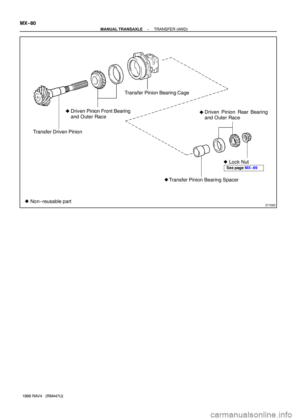
Z17563
Transfer Driven PinionDriven Pinion Front Bearing
and Outer RaceTransfer Pinion Bearing Cage
Driven Pinion Rear Bearing
and Outer Race
� Lock Nut
Transfer Pinion Bearing Spacer
� Non−reusable part�
�
�
See page MX−89
MX−80
− MANUAL TRANSAXLETRANSFER (4WD)
1996 RAV4 (RM447U)

1996 RAV4 (RM447U)
(b) Pull straight until there is a gap of about 60−80 mm
(2.4−3.1 in.) between the engine and tran")

1996 RAV4 (RM447U)
(c) Diaphragm (Free Side):
Inspect the transfer vacuum tank.
(1) Disconnect the solenoid hose No.0, No.1, No.2 and
N")