Page 1166 of 1399
Z07256
ECU Side
−
SUSPENSION AND AXLE DIFFERENTIAL LOCKING SYSTEM
SA−103
960
Author�: Date�:
1996 LAND CRUISER (RM451U) DIFF. fuse/
8 (IG) − Body ground
Ignition switch ONBattery positive voltage
Rear diff. lock position switch/
2 (RLP) − Body groundIgnition switch ON,
Indicator light (Rear) ONAbout 0 V
Ignition switch ON,
Indicator light (Rear) OFFBattery positive voltage
Front diff. lock position switch/ 9 (FLP) − Body ground
Ignition switch ON,
Indicator light (front) ON.About 0 V
Ignition switch ON,
Indicator light (front) OFFBattery positive voltage
Center diff. indicator switch/ 15 (4WD) − Body groud
Ignition switch ON,
Indicator light (Center diff. lock) ONAbout 0 V
Ignition switch ON,
Indicator light (Ce nter diff. lock) OFFBattery positive voltage
Differential lock control switch/
12 (R) − Body ground
Ignition switch ON,
Diff. lock control switch RR or FR RRBattery positive voltage
Ignition switch ON,
Diff. lock control switch OFFAbout 0 V
Differential lock control switch/ 6 (RF) − Body ground
Ignition switch ON,
Diff. lock control switch FR RRBattery positive voltage
Ignition switch ON,
Diff. lock control switch OFF or RRAbout 0 V
HINT:
When a signal enters the ECU to LOCK the front dif ferential and
set the rear differential to FREE (when battery positive voltage
is inputted to terminal 6 (RF) of ECU and about 0 V is inputted
to terminal 12 (R)), or a signal to FREE both the front and rear
differentials, the indicator lights keep blinking until the ignition
switch is turned off (Fail−safe function).
If the circuit is not as specified, check and repair or replace the
trouble part shown in the table above.
(b) Inspect the battery positive voltage Battery positive voltage: 10 − 14.5 V
(c) Inspect the system circuit with connector connected (1) Turn the ignition switch to the ON position.
(2) Keep the center Diff. lock condition.
(3) Remove the Diff. lock ECU.
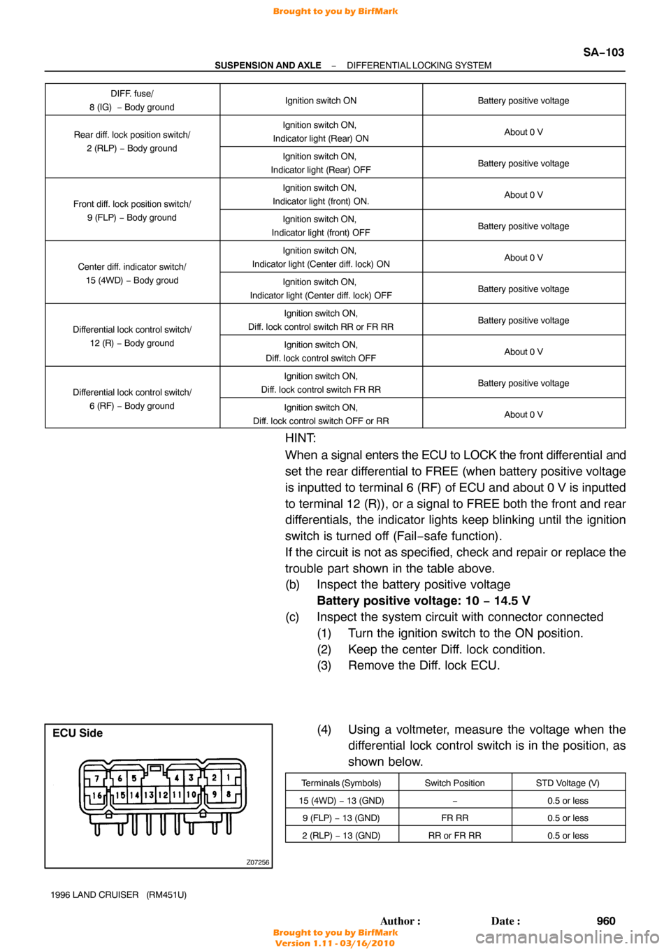
(4) Using a voltmeter, measure the voltage when thedifferential lock control switch is in the position, as
shown below.
Terminals (Symbols)Switch PositionSTD Voltage (V)
15 (4WD) − 13 (GND)−0.5 or less
9 (FLP) − 13 (GND)FR RR0.5 or less
2 (RLP) − 13 (GND)RR or FR RR0.5 or less
Brought to you by BirfMark
Brought to you by BirfMark
Version 1.11 - 03/16/2010
Page 1167 of 1399
W02075
Heater Main Relay
5 Relay Housing
Metallic Parts
3
2
41
Z07257
Free−Lock
Lock−Free
Heater
Main
Relay Battery Battery
Heater
Main
Relay
SA−104
−
SUSPENSION AND AXLE DIFFERENTIAL LOCKING SYSTEM
961
Author�: Date�:
1996 LAND CRUISER (RM451U) 3 (M1) −
1 (M2)
OFF − RR
0.5 or less →
10 − 14.5
(Approx. 1 sec) → 0.5 or less
1 (M2) − 3 (M1)RR − OFF
0.5 or less →
10 − 14.5
(Approx. 1 sec) → 0.5 or less
7 (M3) − 5 (M4)OFF or RR − FR RR
0.5 or less →
10 − 14.5
(Approx. 1 sec) → 0.5 or less
5 (M4) − 7 (M3)FR RR − RR or OFF
0.5 or less →
10 − 14.5
(Approx. 1 sec) → 0.5 or less
If the circuit is not as specified, replace the ECU.
(d) Install the ECU in place.
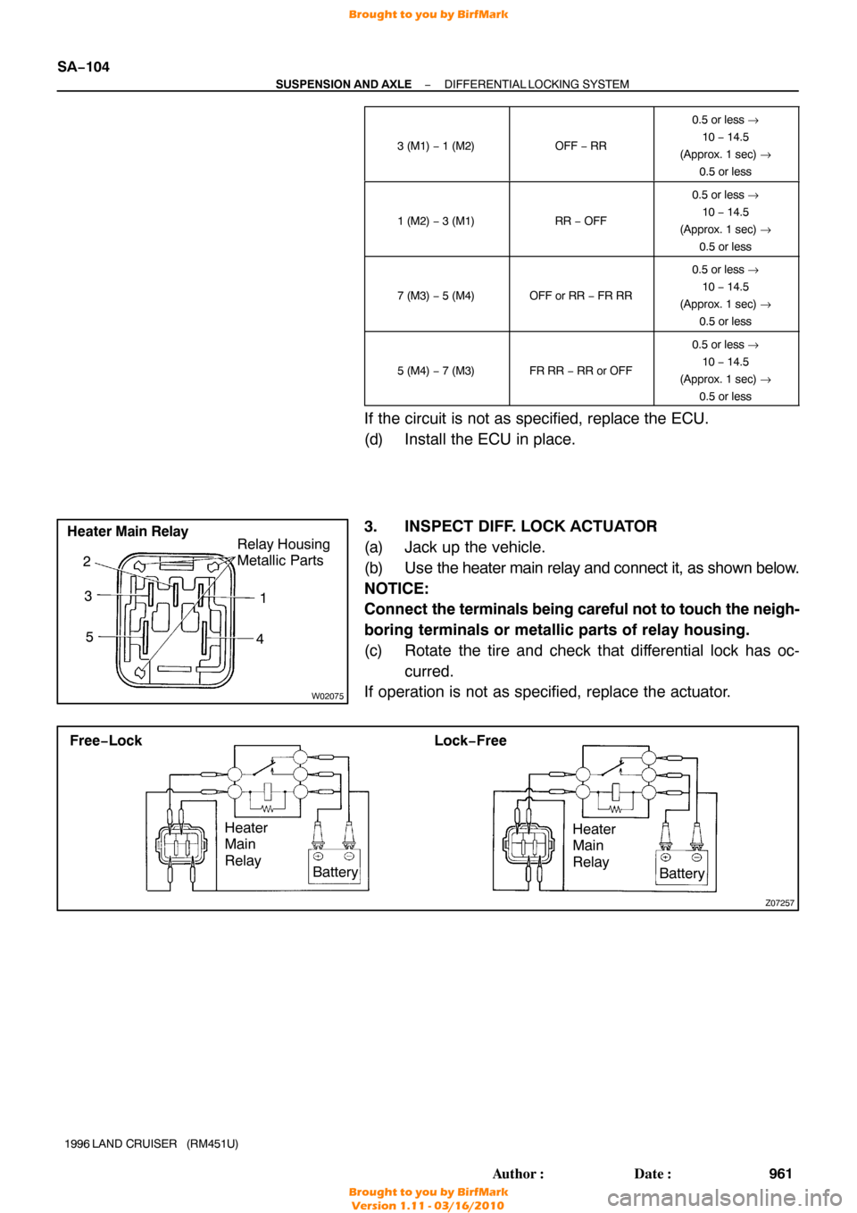
3. INSPECT DIFF. LOCK ACTUATOR
(a) Jack up the vehicle.
(b) Use the heater main relay and connect it, as shown below.
NOTICE:
Connect the terminals being careful not to touch the neigh-
boring terminals or metallic parts of relay housing.
(c) Rotate the tire and check that differential lock has oc- curred.
If operation is not as specified, replace the actuator.
Brought to you by BirfMark
Brought to you by BirfMark
Version 1.11 - 03/16/2010
Page 1190 of 1399
P03244Press Down
Lock
P03245Lock Insert
FI2553
SST
SF−2
−
SFI SFI SYSTEM
630
Author�: Date�:
1996 LAND CRUISER (RM451U)
HINT:
Always check the diagnostic trouble code before disconnecting
the negative ( −) terminal cable from the battery.
(b) When installing the battery, be especially careful not to in-
correctly connect the positive (+) and negative ( −) cables.
(c) Do not permit parts to receive a severe impact during re- moval or installation. Handle all SFI parts carefully, espe-
cially the ECM.
(d) Do not be careless during troubleshooting as there are numerous transistor circuits and even slight terminal con-
tact can further troubles.
(e) Do not open the ECM cover.
(f) When inspecting during rainy weather, take care to pre-
vent entry of water. Also, when washing the engine
compartment, prevent water from getting on the SFI parts
and wiring connectors.
(g) Parts should be replaced as an assembly.
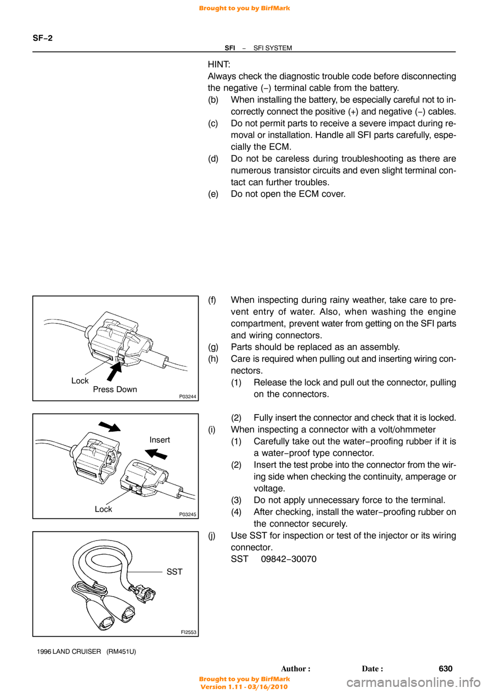
(h) Care is required when pulling out and inserting wiring con-
nectors.
(1) Release the lock and pull out the connector, pulling
on the connectors.
(2) Fully insert the connector and check that it is locked.
(i) When inspecting a connector with a volt/ohmmeter (1) Carefully take out the water −proofing rubber if it is
a water−proof type connector.
(2) Insert the test probe into the connector from the wir-
ing side when checking the continuity, amperage or
voltage.
(3) Do not apply unnecessary force to the terminal.
(4) After checking, install the water−proofing rubber on
the connector securely.
(j) Use SST for inspection or test of the injector or its wiring connector.
SST 09842−30070
Brought to you by BirfMark
Brought to you by BirfMark
Version 1.11 - 03/16/2010
Page 1242 of 1399
SF1F5−01
P05668
OhmmeterContinuity
Ohmmeter
No Continuity
1
2
43
P05667
Ohmmeter 1
2
3
4 Battery
SF−56
−
SFI CIRCUIT OPENING RELAY
1996 LAND CRUISER (RM451U)
INSPECTION
1. REMOVE CIRCUIT OPENING RELAY
2. INSPECT CIRCUIT OPENING RELAY CONTINUITY
(a) Using an ohmmeter, check that there is continuity be- tween terminals 1 and 3.
(b) Check that there is no continuity between terminals 2 and
4.
If continuity is not as specified, replace the relay.
3. INSPECT CIRCUIT OPENING RELAY OPERATION
(a) Apply battery voltage across terminals 1 and 3.
(b) Using an ohmmeter, check that there is continuity be- tween terminals 2 and 4.
If operation is not as specified, replace the relay.
4. REINSTALL CIRCUIT OPENING RELAY
Brought to you by BirfMark
Brought to you by BirfMark
Version 1.11 - 03/16/2010
Page 1245 of 1399
SF1F9−01
−
SFI VSV FOR FUEL PRESSURE CONTROL
SF−59
687
Author�: Date�:
1996 LAND CRUISER (RM451U)
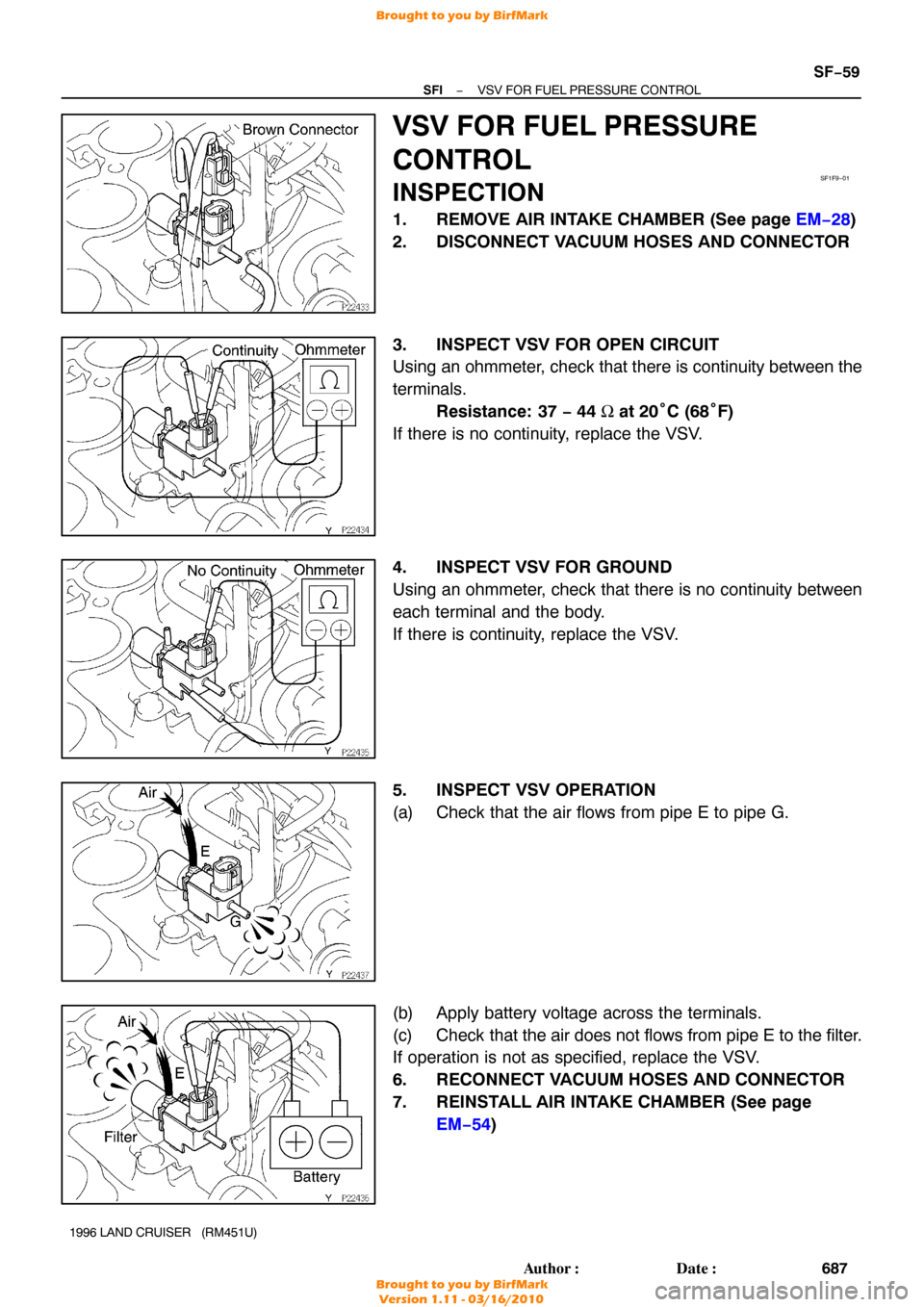
VSV FOR FUEL PRESSURE
CONTROL
INSPECTION
1. REMOVE AIR INTAKE CHAMBER (See page EM−28 )
2. DISCONNECT VACUUM HOSES AND CONNECTOR
3. INSPECT VSV FOR OPEN CIRCUIT
Using an ohmmeter, check that there is continuity between the
terminals. Resistance: 37 − 44 Ω at 20° C (68°F)
If there is no continuity, replace the VSV.
4. INSPECT VSV FOR GROUND
Using an ohmmeter, check that there is no continuity between
each terminal and the body.
If there is continuity, replace the VSV.
5. INSPECT VSV OPERATION
(a) Check that the air flows from pipe E to pipe G.
(b) Apply battery voltage across the terminals.
(c) Check that the air does not flows from pipe E to the filter.
If operation is not as specified, replace the VSV.
6. RECONNECT VACUUM HOSES AND CONNECTOR
7. REINSTALL AIR INTAKE CHAMBER (See page EM−54 )
Brought to you by BirfMark
Brought to you by BirfMark
Version 1.11 - 03/16/2010
Page 1398 of 1399
Q02622
Light upGoes off
L
NH
DIFF LOCK
DIFF LOCK
TR0BM−03
Z15367
Relay Side
V01699
V06651
−
TRANSFER MOTOR SHIFT CONTROL SYSTEM
TR−37
1996 LAND CRUISER (RM451U)
INSPECTION
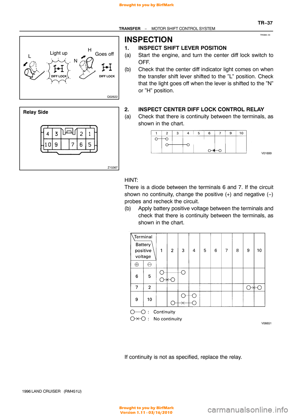
1. INSPECT SHIFT LEVER POSITION
(a) Start the engine, and turn the center diff lock switch to
OFF.
(b) Check that the center diff indicator light comes on when the transfer shift lever shifted to the ”L” position. Check
that the light goes off when the lever is shifted to the ”N”
or ”H” position.
2. INSPECT CENTER DIFF LOCK CONTROL RELAY
(a) Check that there is continuity between the terminals, as shown in the chart.
HINT:
There is a diode between the terminals 6 and 7. If the circuit
shown no continuity, change the positive (+) and negative ( −)
probes and recheck the circuit.
(b) Apply battery positive voltage between the terminals and check that there is continuity between the terminals, as
shown in the chart.
If continuity is not as specified, replace the relay.
Brought to you by BirfMark
Brought to you by BirfMark
Version 1.11 - 03/16/2010