Page 813 of 1399

EM1E3−01
EM−28
−
ENGINE MECHANICAL CYLINDER HEAD
1996 LAND CRUISER (RM451U)
REMOVAL
1. DRAIN ENGINE COOLANT
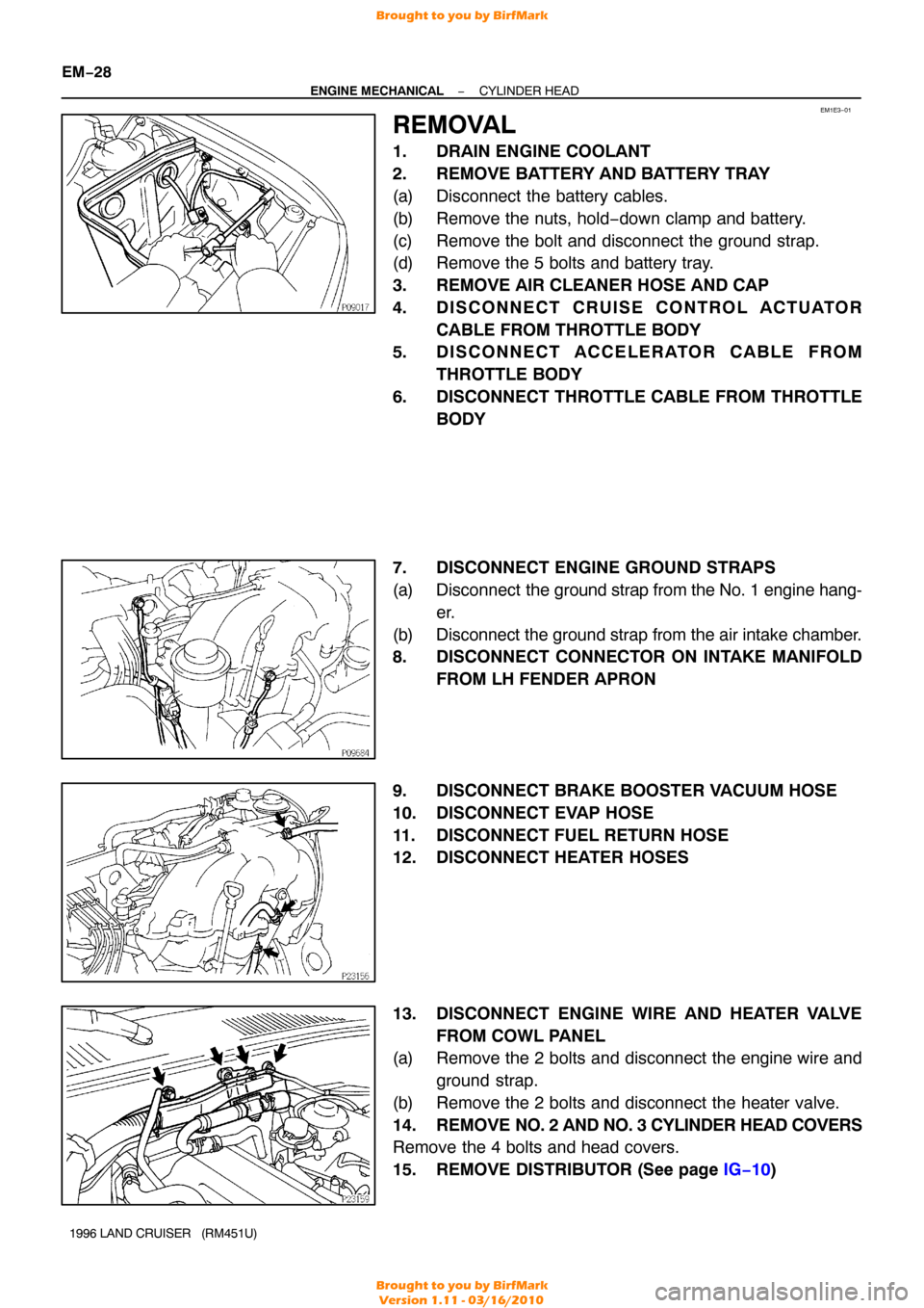
2. REMOVE BATTERY AND BATTERY TRAY
(a) Disconnect the battery cables.
(b) Remove the nuts, hold −down clamp and battery.
(c) Remove the bolt and disconnect the ground strap.
(d) Remove the 5 bolts and battery tray.
3. REMOVE AIR CLEANER HOSE AND CAP
4. DISCONNECT CRUISE CONTROL ACTUATOR CABLE FROM THROTTLE BODY
5. DISCONNECT ACCELERATOR CABLE FROM
THROTTLE BODY
6. DISCONNECT THROTTLE CABLE FROM THROTTLE BODY
7. DISCONNECT ENGINE GROUND STRAPS
(a) Disconnect the ground strap from the No. 1 engine hang-
er.
(b) Disconnect the ground strap from the air intake chamber.
8. DISCONNECT CONNECTOR ON INTAKE MANIFOLD FROM LH FENDER APRON
9. DISCONNECT BRAKE BOOSTER VACUUM HOSE
10. DISCONNECT EVAP HOSE
11. DISCONNECT FUEL RETURN HOSE
12. DISCONNECT HEATER HOSES
13. DISCONNECT ENGINE WIRE AND HEATER VALVE FROM COWL PANEL
(a) Remove the 2 bolts and disconnect the engine wire and
ground strap.
(b) Remove the 2 bolts and disconnect the heater valve.
14. REMOVE NO. 2 AND NO. 3 CYLINDER HEAD COVERS
Remove the 4 bolts and head covers.
15. REMOVE DISTRIBUTOR (See page IG−10 )
Brought to you by BirfMark
Brought to you by BirfMark
Version 1.11 - 03/16/2010
Page 848 of 1399

−
ENGINE MECHANICAL CYLINDER HEAD
EM−63
1996 LAND CRUISER (RM451U)
24. CONNECT NO. 3 WATER BYPASS HOSE
25. CONNECT RADIATOR INLET HOSE
26. CONNECT PS RESERVOIR TANK
Connect the reservoir tank with the 3 bolts.
Torque: 20 N·m (200 kgf·cm, 14 ft·lbf)
27. INSTALL DISTRIBUTOR (See page IG−11)
28. INSTALL NO. 2 AND NO. 3 CYLINDER HEAD COVERS
Install the head covers with the 4 bolts.
29. CONNECT HEATER VALVE AND ENGINE WIRE TO COWL PANEL
(a) Connect the heater valve with the 2 bolts.
(b) Connect the engine wire and ground strap with the 2 bolts.
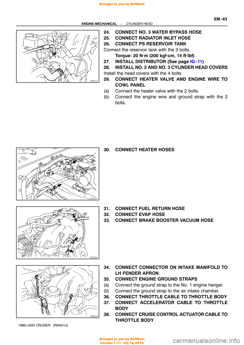
30. CONNECT HEATER HOSES
31. CONNECT FUEL RETURN HOSE
32. CONNECT EVAP HOSE
33. CONNECT BRAKE BOOSTER VACUUM HOSE
34. CONNECT CONNECTOR ON INTAKE MANIFOLD TO LH FENDER APRON
35. CONNECT ENGINE GROUND STRAPS
(a) Connect the ground strap to the No. 1 engine hanger.
(b) Connect the ground strap to the air intake chamber.
36. CONNECT THROTTLE CABLE TO THROTTLE BODY
37. CONNECT ACCELERATOR CABLE TO THROTTLE
BODY
38. CONNECT CRUISE CONTROL ACTUATOR CABLE TO
THROTTLE BODY
Brought to you by BirfMark
Brought to you by BirfMark
Version 1.11 - 03/16/2010
Page 866 of 1399

−
ENGINE MECHANICAL ENGINE UNIT
EM−81
1996 LAND CRUISER (RM451U)
26. CONNECT EVAP HOSE
27. CONNECT BRAKE BOOSTER VACUUM HOSE
28. CONNECT HEATER VALVE AND ENGINE WIRE TO
COWL PANEL
(a) Connect the heater valve with the 2 bolts.
(b) Connect the engine wire and ground strap with the 2 bolts.
29. CONNECT HEATER HOSES
30. CONNECT ACCELERATOR CABLE TO THROTTLE BODY
31. CONNECT CRUISE CONTROL ACTUATOR CABLE TO
THROTTLE BODY
32. INSTALL AIR CLEANER CASE
33. INSTALL AIR CLEANER HOSE AND CAP
34. CONNECT OIL COOLER HOSE TO OIL COOLER PIPE
35. INSTALL RADIATOR (See page CO−16)
36. INSTALL RADIATOR GRILLE
Install the radiator grille with the 5 screws and clip.
37. INSTALL BATTERY TRAY AND BATTERY
(a) Install the battery tray with the 5 bolts.
(b) Connect the ground strap with the bolt.
(c) Install the battery and hold−down clamp with the nuts.
(d) Connect the battery cables.
38. FILL WITH ENGINE OIL
39. FILL RADIATOR WITH ENGINE COOLANT
40. START ENGINE AND CHECK FOR LEAKS
41. CHECK AUTOMATIC TRANSMISSION FLUID LEVEL
42. CHECK IGNITION TIMING (See page EM−10)
43. INSTALL HOOD
44. PERFORM ROAD TEST
Check for abnormal noise, shock, slippage, correct shift points
and smooth operation.
45. RECHECK ENGINE COOLANT AND ENGINE OIL LEV-
ELS
Brought to you by BirfMark
Brought to you by BirfMark
Version 1.11 - 03/16/2010
Page 1263 of 1399

SR−12
−
STEERING TILT STEERING COLUMN
1996 LAND CRUISER (RM451U)
3. REMOVE INSTRUMENT LOWER FINISH PANEL
(a) Disconnect the hood lock control cable and fuel lid control
cable.
(b) Remove the 4 panel set screws.
4. REMOVE NO.2 HEATER TO REGISTER DUCT
5. REMOVE UPPER AND LOWER COLUMN COVERS
Remove the 5 screws.
6. REMOVE COMBINATION SWITCH WITH SPIRAL CABLE
(a) Disconnect the 2 connectors.
(b) Disconnect the airbag connector.
(c) Remove the 4 screws.
NOTICE:
Do not disassemble the cable or apply oil to it.
7. REMOVE 4 COLUMN HOLE COVER SET BOLTS
8. REMOVE LINK JOINT PROTECTOR
Remove the 2 bolts.
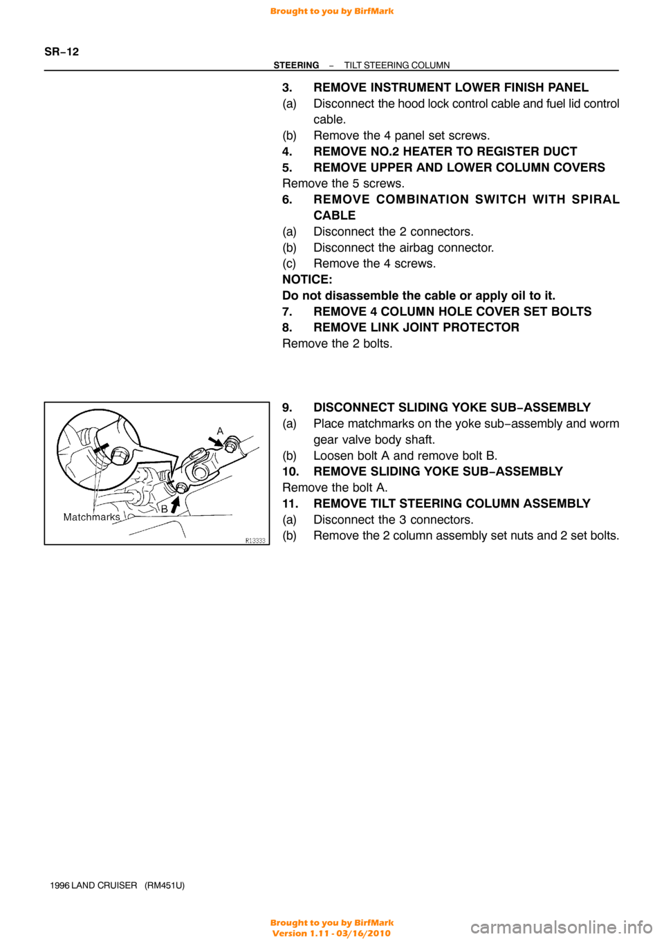
9. DISCONNECT SLIDING YOKE SUB−ASSEMBLY
(a) Place matchmarks on the yoke sub −assembly and worm
gear valve body shaft.
(b) Loosen bolt A and remove bolt B.
10. REMOVE SLIDING YOKE SUB−ASSEMBLY
Remove the bolt A.
11. REMOVE TILT STEERING COLUMN ASSEMBLY
(a) Disconnect the 3 connectors.
(b) Remove the 2 column assembly set nuts and 2 set bolts.
Brought to you by BirfMark
Brought to you by BirfMark
Version 1.11 - 03/16/2010
Page 1270 of 1399

SR16E−03
−
STEERING TILT STEERING COLUMN
SR−19
1996 LAND CRUISER (RM451U)
INSTALLATION
1. INSTALL STEERING COLUMN ASSEMBLY
(a) Torque the 2 column assembly set nuts and 2 set bolts.
Torque:25 N·m (250 kgf·cm, 18 ft·lbf)
(b) Connect the 3 connectors.
2. INSTALL SLIDING YOKE SUB −ASSEMBLY
Temporarily tighten the bolt A.
3. CONNECT SLIDING YOKE SUB−ASSEMBLY
(a) Align the matchmarks on the yoke sub−assembly and
worm gear valve body shaft.
(b) Torque the bolt B. Torque: 34 N·m (350 kgf·cm, 25 ft·lbf)
(c) Torque the bolt A.
Torque: 34 N·m (350 kgf·cm, 25 ft·lbf)
4. INSTALL LINK JOINT PROTECTOR
Torque the 2 bolts. Torque: 12 N·m (120 kgf·cm, 9 ft·lbf)
5. TORQUE 4 COLUMN HOLE COVER SET BOLTS Torque: 13 N·m (130 kgf·cm, 9 ft·lbf)
6. INSTALL COMBINATION SWITCH WITH SPIRAL CABLE
(a) Tighten the 4 screws.
(b) Connect the airbag connector.
(c) Connect the 2 connectors.
7. INSTALL UPPER AND LOWER COLUMN COVERS
Tighten the 5 screws.
8. INSTALL NO.2 HEATER TO REGISTER DUCT
9. INSTALL INSTRUMENT LOWER FINISH PANEL
(a) Tighten the 4 panel set screws.
(b) Connect the hood lock control cable and fuel lid control cable.
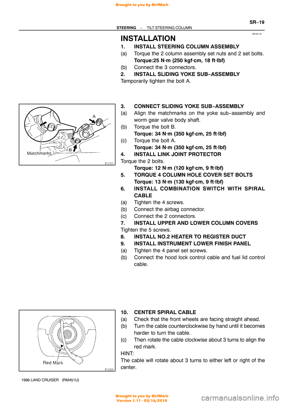
10. CENTER SPIRAL CABLE
(a) Check that the front wheels are facing straight ahead.
(b) Turn the cable counterclockwise by hand until it becomes harder to turn the cable.
(c) Then rotate the cable clockwise about 3 turns to align the
red mark.
HINT:
The cable will rotate about 3 turns to either left or right of the
center.
Brought to you by BirfMark
Brought to you by BirfMark
Version 1.11 - 03/16/2010