Page 1025 of 1399

SRS AIRBAG
PRECAUTION
NOTICE:
�The LAND CRUISER is equipped with an SRS , which compri")
RS0OZ−02
−
SUPPLEMENTAL RESTRAINT SYSTEM SRS AIRBAG
RS−1
1100
Author�: Date�:
1996 LAND CRUISER (RM451U)
SRS AIRBAG
PRECAUTION
NOTICE:
�The LAND CRUISER is equipped with an SRS , which comprises a driver airbag \
and a front pas-
senger airbag. Failure to carry out service operations in the correct sequence could cause the
SRS to unexpectedly deploy during servicing, possibly leading to a serio\
us accident. Further,
if a mistake is made in servicing the SRS, it is possible the SRS may fail to\
operate when re-
quired. Before performing servicing (including removal or installation \
of parts, inspection or
replacement), be sure to read the following items carefully, then follow the correct procedure
described in the repair manual.
�Malfunction symptoms of the SRS are difficult to confirm, so the DTCs become the mos\
t impor-
tant source of information when troubleshooting. When troubleshooting th\
e SRS, always in-
spect the DTCs before disconnecting the battery.
�Even in cases of a minor collision where the SRS does not deploy, the steering wheel pad, front
passenger airbag assembly, and airbag sensor assembly should be inspected (See pages
RS−9 , RS−23 and RS−34 )
�Never use SRS parts from another vehicle. When replacing parts, replace them with \
new parts.
�Never disassemble and repair the steering wheel pad, front passenger airbag assembly , or air-
bag sensor assembly in order to reuse it.
�If the steering wheel pad, front passenger airbag assembly or airbag sen\
sor assembly have
been dropped, or if there are cracks, dents or other defects in the case, br\
acket or connector,
replace them with new ones.
�Use a volt/ohmmeter wi th high impedance (10 k Ω/V minimum) for troubleshooting the system’s
electrical circuits.
�Information labels are attached to the periphery of the SRS components. Follow the instruc-
tions on the notices.
�After work on the SRS is completed, check the SRS warning light (See pa\
ge DI−240).
�If the vehicle is equipped with a mobile communication system, refer to the precaution in the
IN section.
CAUTION:
�Work must be started after 90 seconds from the time the ignition switch is t\
urned to the ”LOCK”
position and the negative ( −) terminal cable is disconnected from the battery.
(The SRS is equipped with a back− up power source so that if work is started within 90 seconds
of disconnecting the negative ( −) terminal cable of the battery, the SRS may be deployed.)
�When the negative (−) terminal cable is disconnected from the battery, the memory of the clock
and audio system will be canceled. So before starting work, make a record o\
f the contents mem-
orized in the audio memory system. When work is finished, reset the audio syst\
ems as they
were before and adjust the clock. To avoid erasing the memory of each memory system, never
use a back−up power supply from outside the vehicle.
�Before repairs, remove the airbag sensor if shocks are likely to be applied to the senso\
r during
repairs.
�Do not expose the steering wheel pad, front passenger airbag assembly, or airbag sensor as-
sembly directly to hot air or flames.
Brought to you by BirfMark
Brought to you by BirfMark
Version 1.11 - 03/16/2010
Page 1064 of 1399

TROUBLESHOOTING
PROBLEM SYMPTOMS TABLE
Use the table below to help you find the cause of the")
SA1U7−01
−
SUSPENSION AND AXLE TROUBLESHOOTING
SA−1
858
Author�: Date�:
1996 LAND CRUISER (RM451U)
TROUBLESHOOTING
PROBLEM SYMPTOMS TABLE
Use the table below to help you find the cause of the problem. The numbers \
indicate the priority of the likely
cause of the problem. Check each part in order. If necessary, replace these parts.
(w/ Differential locking system):
�Check that center differential lock mode is set.
�When switching differential Free↔Lock, the indicator lamp will blink if the gears of the differen-
tial lock sleeve are not meshed. If this occurs, when the tires are rotated \
to apply differential
power to the differential, the differential locks and the indicator lamp\
light up.
SymptomSuspect AreaSee page
Wander/ pulls
1. Tires: worn or improperly inflated
2. Wheel alignmemt: incorrect
3. Steering linkage: loosen or worn
4. Hub bearings: loosen or worn
5. Steering gear: out of adjustment or brokenSA−3
SA−4
SR−47 SA−8
SR−41
Bottoming
1. Vehicle: overloaded
2. Spring weak
3. Shock absorber: worn out−
SA−49
SA−49
Sways/ pitches
1. Tires: worn or improperly inflated
2. Stabilizer bar: bent or broken
3. Shock absorber: worn outSA−3
SA−60
SA−49
Front wheel shimmy
1. Tires: worn or improperly inflated
2. Wheels: out of balance
3. Shock absorber: worn out
4. Wheel alignmemt: incorrect
5. Hub bearings: loosen or worn
6. Steering linkage: loosen or worn
7. Steering gear: out of adjustment or brokenSA−3
SA−3
SA−49 SA−3
SA−7
SR−45
SR−38
Abnormal tire wear
1. Tires: worn or improperly inflated
2. Wheel alignmemt: incorrect
3. Suspension parts: worn out
4. Shock absorber: worn outSA−3
SA−3 −
SA−49
Noise in front dif ferential
1. Oil level: low or wrong grade
2. Excessive backlash between pinion and ring gear
3. Ring, pinion ro side gears: worn or chipped
4. Pinion shaft bearing: worn
5. Side bearing: worn
6. Differential bearing: loosen or wornSA−21
SA−29
SA−29
SA−29
SA−29
SA−29
Oil leak from front dif ferential
1. Oil level: too high or wrong grade
2. Drive pinion oil seal: worn or damaged
3. Side gear oil seal: worn or damaged
4. Companion flange: loosen or damaged
5. Side gear shaft: damagedSA−21
SA−29
SA−29
SA−29
SA−29
Noise in rear axle
1. Oil level: low or wrong grade
2. Excessive backlash between pinion and ring gear
3. Ring, pinion ro side gears: worn or chipped
4. Pinion shaft bearing: worn
5. Axle shaft bearing: worn
6. Differential bearing: loosen or wornSA−73
SA−87
SA−87
SA−87
SA−87
SA−87
Oil leak from rear axle1. Oil seal: worn or damaged
2. Rear axle housing: crackedSA−73
−
Brought to you by BirfMark
Brought to you by BirfMark
Version 1.11 - 03/16/2010
Page 1068 of 1399

HINT:
Th")
R05626
Front
Side+10
° +60
°
−10 °
FA0507
FA0018
A B
Front BA
A: Inside
B: Outside
−
SUSPENSION AND AXLE FRONT WHEEL ALIGNMENT
SA−5
862
Author�: Date�:
1996 LAND CRUISER (RM451U)
HINT:
The clamps opening must be positioned at the rear of the tie rod
end face within 60 °±10° from the vehicle axis.
6. INSPECT WHEEL ANGLE
(a) Remove the caps of the knuckle stopper bolts and check the steering angles.
(b) Turn the steering wheel fully, and measure the turning angle.
Inside wheel32°00’ − 35°00’
Outside wheel31 °00’ (Reference)
HINT:
When the steering wheel is fully turned, make sure that the
wheel is not touching the body or brake flexible hose.
If maximum steering angles differ from the standard value, ad-
just the wheel angle with the knuckle stopper bolts.
Torque: 44 N·m (450 kgf·cm, 33 ft·lbf)
If the wheel angle still cannot be adjusted within limits, inspect
and replace damaged or worn steering parts.
Brought to you by BirfMark
Brought to you by BirfMark
Version 1.11 - 03/16/2010
Page 1083 of 1399
SA1UJ−01
SA−20
−
SUSPENSION AND AXLE FRONT DIFFERENTIAL REAR OIL SEAL
877
Author�: Date�:
1996 LAND CRUISER (RM451U)
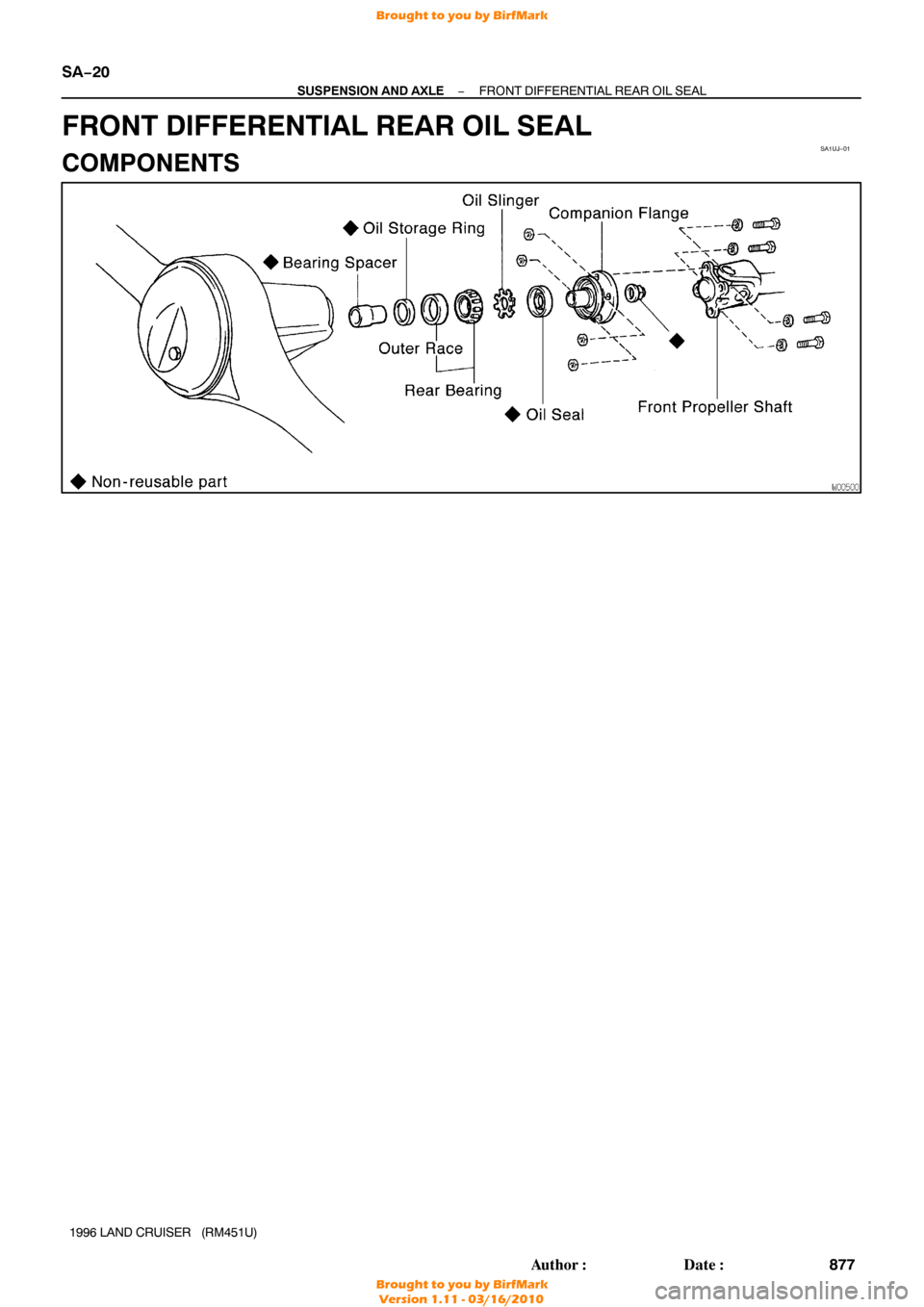
FRONT DIFFERENTIAL REAR OIL SEAL
COMPONENTS
Brought to you by BirfMark
Brought to you by BirfMark
Version 1.11 - 03/16/2010
Page 1084 of 1399
SA1UK−01
Z15176
SST
R13186
SST
SA1973
SST
SA1969
SST
−
SUSPENSION AND AXLE FRONT DIFFERENTIAL REAR OIL SEAL
SA−21
1996 LAND CRUISER (RM451U)
REPLACEMENT
1. DRAIN DIFFERENTIAL OIL
2. REMOVE FRONT PROPELLER SHAFT
(See page PR−3 )
3. REMOVE COMPANION FLANGE
(a) Using a chisel and hammer, loosen the staked part of the
nut.
(b) Using SST to hold the flange, remove the nut and plate washer.
SST 09330−00021
(c) Using SST, remove the companion flange. SST 09950−30010 (09951 −03010, 09953−03010,
09954 −03010, 09955 −03030, 09956−03020)
4. REMOVE OIL SEAL AND OIL SLINGER
(a) Using SST, remove the oil seal. SST 09308−10010
(b) Remove the oil slinger.
5. REMOVE REAR BEARING
Using SST, remove the rear bearing from the drive pinion. SST 09556−22010
Brought to you by BirfMark
Brought to you by BirfMark
Version 1.11 - 03/16/2010
Page 1085 of 1399

R13139
SST
SA−22
−
SUSPENSION AND AXLE FRONT DIFFERENTIAL REAR OIL SEAL
1996 LAND CRUISER (RM451U)
6")
SA2430
SST
SA2271
R13155
SSTSST
Oil Storage Ring
Rear Bearing
SA2411
SST
1.0 mm (10.039 in.)
R13139
SST
SA−22
−
SUSPENSION AND AXLE FRONT DIFFERENTIAL REAR OIL SEAL
1996 LAND CRUISER (RM451U)
6. REMOVE REAR BEARING OUTER RACE
Using SST, remove the bearing outer race.
SST 09308−00010
NOTICE:
Do not scratch the taper surface of the outer race.
7. REMOVE OIL STORAGE RING
Using a screwdriver, bend the oil storage ring and drive it out.
8. REMOVE BEARING SPACER
9. INSTALL BEARING SPACER
10. INSTALL OIL STORAGE RING
Using SST, install a new oil storage ring. SST 09316−60011 (09316 −00011, 09316−00021)
11. INSTALL REAR BEARING
(a) Using SST, install the bearing outer race.
SST 09316−60011 (09316 −00011, 09316−00021)
(b) Install the rear bearing.
12. INSTALL OIL SLINGER AND OIL SEAL
(a) Install the oil slinger.
(b) Using SST, install a new oil seal, as shown. SST 09214−76011
Oil seal drive in depth: 1.0 mm (0.039 in.)
(c) Coat the lip of the oil seal with MP grease.
13. INSTALL COMPANION FLANGE
(a) Using SST, install the companion flange on the drive pin- ion.
SST 09950−30010 (09951 −03010, 09953−03010,
09954 −03010, 09955 −03030, 09956−03020)
(b) Place the plate washer on the companion flange.
Brought to you by BirfMark
Brought to you by BirfMark
Version 1.11 - 03/16/2010
Page 1086 of 1399
SA1960
SST
RA1072
Filler Hole
Oil
0 − 5 mm (0 − 0.20 in.)
−
SUSPENSION AND AXLE FRONT DIFFERENTIAL REAR OIL SEAL
SA−23
1996 LAND CRUISER (RM451U)
(c) Apply light coat of gear oil on threads of a new companion
flange nut.
(d) Using SST to hold the flange, torque the nut.
SST 09330−00021
Torque: 196 N·m (2,000 kgf·cm, 145 ft·lbf)
14. ADJUST DRIVE PINION PRELOAD (See page SA−36 )
15. STAKE DRIVE PINION NUT
16. INSTALL FRONT PROPELLER SHAFT (See page PR−5 )
17. FILL DIFFERENTIAL WITH GEAR OIL Torque: 49 N·m (500 kgf·cm, 39 ft·lbf)
Oil type: Hypoid gear oil API GL −5
Recommended oil viscosity:
Above −18°C (0° F) SAE 90
Below −18°C (0° F) SAE 80W−90 or 80W
Capacity:
w/o Differential lock:
2.80 liters (2.9 US qts, 2.5 Imp. qts)
w/ Differential lock:
2.65 liters (2.8 US qts, 2.3 Imp. qts)
Brought to you by BirfMark
Brought to you by BirfMark
Version 1.11 - 03/16/2010
Page 1087 of 1399
SA1UL−01
SA−24
−
SUSPENSION AND AXLE FRONT DIFFERENTIAL CARRIER
881
Author�: Date�:
1996 LAND CRUISER (RM451U)
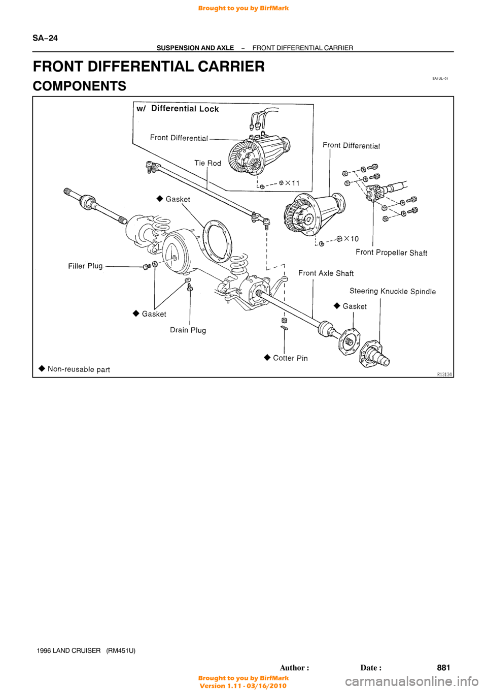
FRONT DIFFERENTIAL CARRIER
COMPONENTS
Brought to you by BirfMark
Brought to you by BirfMark
Version 1.11 - 03/16/2010

REPLACEMENT
1. DRAIN DIFFERENTIAL OIL
2. REMOVE FRO")

−
SUSPENSION AND AXLE FRONT DIFFERENTIAL REAR OIL SEAL
SA−23
1996 LAND CRUISER (RM451U)
(c) Apply light coat of gear oil on threa")