Page 1339 of 1399

SS1EH−02
SS−38
−
SERVICE SPECIFICATIONS STEERING
1996 LAND CRUISER (RM451U)
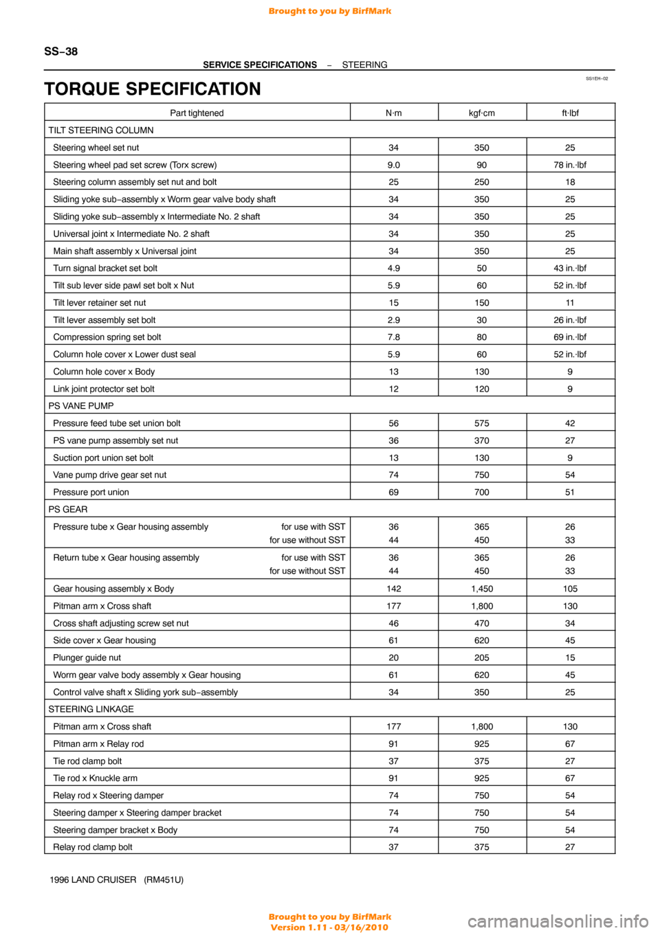
TORQUE SPECIFICATION
Part tightenedN·mkgf·cmft·lbf
TILT STEERING COLUMN
Steering wheel set nut3435025
Steering wheel pad set screw (T orx screw)9.09078 in.·lbf
Steering column assembly set nut and bolt2525018
Sliding yoke sub−assembly x Worm gear valve body shaft3435025
Sliding yoke sub −assembly x Intermediate No. 2 shaft3435025
Universal joint x Intermediate No. 2 shaft3435025
Main shaft assembly x Universal joint3435025
Turn signal bracket set bolt4.95043 in.·lbf
Tilt sub lever side pawl set bolt x Nut5.96052 in.·lbf
Tilt lever retainer set nut1515011
Tilt lever assembly set bolt2.93026 in.·lbf
Compression spring set bolt7.88069 in.·lbf
Column hole cover x Lower dust seal5.96052 in.·lbf
Column hole cover x Body131309
Link joint protector set bolt121209
PS VANE PUMP
Pressure feed tube set union bolt5657542
PS vane pump assembly set nut3637027
Suction port union set bolt131309
Vane pump drive gear set nut7475054
Pressure port union6970051
PS GEAR
Pressure tube x Gear housing assembly for use with SST
for use without SST36
44365
45026
33
Return tube x Gear housing assembly for use with SST
for use without SST36
44365
45026
33
Gear housing assembly x Body1421,450105
Pitman arm x Cross shaft1771,800130
Cross shaft adjusting screw set nut4647034
Side cover x Gear housing6162045
Plunger guide nut2020515
Worm gear valve body assembly x Gear housing6162045
Control valve shaft x Sliding york sub −assembly3435025
STEERING LINKAGE
Pitman arm x Cross shaft1771,800130
Pitman arm x Relay rod9192567
Tie rod clamp bolt3737527
Tie rod x Knuckle arm9192567
Relay rod x Steering damper7475054
Steering damper x Steering damper bracket7475054
Steering damper bracket x Body7475054
Relay rod clamp bolt3737527
Brought to you by BirfMark
Brought to you by BirfMark
Version 1.11 - 03/16/2010
Page 1343 of 1399
SS−42
−
SERVICE SPECIFICATIONS BODY
165
Author�: Date�:
1996 LAND CRUISER (RM451U)
Seat lock x Seat cushion frame
4142030
NO. 2 REAR SEAT
Reclining adjuster x Seatback frame5253038
Seat leg x Body1818513
POWER SEAT ADJUSTER
No. 2 vertical seat link x Rear vertical motor
Bolt
Nut10 2100207
17 in.·lbf
No. 1 vertical seat link x Front vertical motor101007
Seat truck x Seat truck inner reinforcement2021015
Front seat horizontal seat screw x Front seat motor slide housing1920014
Slide motor x Front seat horizontal jack screw Bolt
Nut10 2100207
17 in.·lbf
Front seat horizontal jack screw x Front seat truck1920014
SEAT BELT
Adjustable anchor x Body4344032
ELR x Body55043 in.·lbf
Outer belt anchor x Body4344032
Inner belt x Seat4344032
SIDE STEP
Side step bracket x Body131309
Side step bracket x Side panel5.45548 in.·lbf
Brought to you by BirfMark
Brought to you by BirfMark
Version 1.11 - 03/16/2010
Page 1345 of 1399
SS1EM−02
SS−44
−
SERVICE SPECIFICATIONS AIR CONDITIONING
1996 LAND CRUISER (RM451U)
TORQUE SPECIFICATION
Part tightenedN·mkgf·cmft·lbf
Compressor x Suction hose101007
Compressor x Discharge hose101007
Condensser x Compressor bracket2525018
Compressor bracket x Engine3737527
Receiver x Liquid tube5.45548 in.·lbf
Condenser x Discharge hose101007
Cooling unit x Liqied tube101007
Cooling unit x Suction tube101007
Pressure switch x Liquid tube101007
Expansion valve x Evaporetor5.45548 in.·lbf
Liquid line (Union nut)1414010
Suction line (bolt)101407
Brought to you by BirfMark
Brought to you by BirfMark
Version 1.11 - 03/16/2010
Page 1349 of 1399
ST0KP−01
ST−4
−
STARTING STARTER
1996 LAND CRUISER (RM451U)
REMOVAL
REMOVE STARTER
(a) Disconnect the starter connector.
(b) Remove the nut, and disconnect the starter wire. Torque: 8.8 N·m (90 kgf·cm, 70 in.·lbf)
(c) Remove the 2 bolts and starter. Torque: 39 N·m (400 kgf·cm, 29 ft·lbf)
Brought to you by BirfMark
Brought to you by BirfMark
Version 1.11 - 03/16/2010
Page 1350 of 1399

ST0KQ−01
P23005
P23006
P08385
P23007
−
STARTING STARTER
ST−5
1996 LAND CRUISER (RM451U)
DISASSEMBLY
HINT:
At the time of reassembly, use high−temperature grease to lu-
bricate the bearings, gears, return spring and steel ball when
assembling the starter.
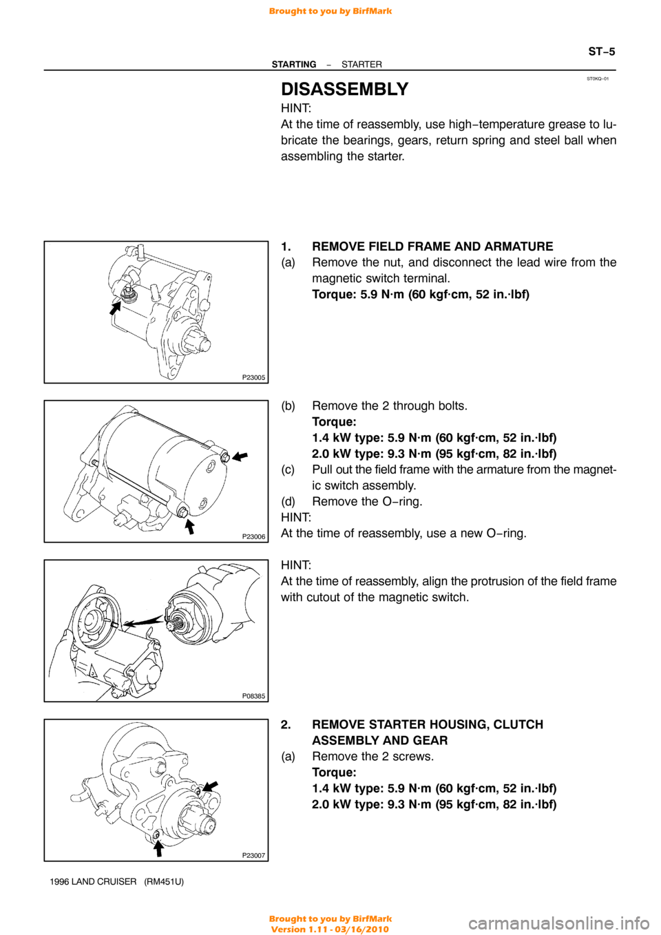
1. REMOVE FIELD FRAME AND ARMATURE
(a) Remove the nut, and disconnect the lead wire from the
magnetic switch terminal.
Torque: 5.9 N·m (60 kgf·cm, 52 in.·lbf)
(b) Remove the 2 through bolts. Torque:
1.4 kW type: 5.9 N·m (60 kgf·cm, 52 in.·lbf)
2.0 kW type: 9.3 N·m (95 kgf·cm, 82 in.·lbf)
(c) Pull out the field frame with the armature from the magnet-
ic switch assembly.
(d) Remove the O−ring.
HINT:
At the time of reassembly, use a new O−ring.
HINT:
At the time of reassembly, align the protrusion of the field frame
with cutout of the magnetic switch.
2. REMOVE STARTER HOUSING, CLUTCH ASSEMBLY AND GEAR
(a) Remove the 2 screws.
Torque:
1.4 kW type: 5.9 N·m (60 kgf·cm, 52 in.·lbf)
2.0 kW type: 9.3 N·m (95 kgf·cm, 82 in.·lbf)
Brought to you by BirfMark
Brought to you by BirfMark
Version 1.11 - 03/16/2010
Page 1356 of 1399
P10593
SST
ST0N9−01
P10595
SST
P10596
Upword
Downword SST
−
STARTING STARTER
ST−11
1996 LAND CRUISER (RM451U)
REPLACEMENT
1. REPLACE REAR BEARING
(a) Using SST, remove the bearing.
SST 09286−46011
(b) Using a press, press in a new rear bearing.
2. REPLACE FRONT BEARING
(a) Using SST, remove the bearing. SST 09286−46011
(b) Using a press, press in a new front bearing.
NOTICE:
Be careful of the bearing installation direction. SST 09820−00030
3. REMOVE MAGNETIC SWITCH END COVER
Remove the 3 bolts, lead clamp, end cover, gasket and plunger.
4. INSPECT CONTACT PLATE FOR WEAR
Using vernier calipers, measure the contact plate for depth of
wear. Maximum wear: 0.9 mm (0.035 in.)
If the depth of wear is greater than the maximum, replace the
contact plate.
Brought to you by BirfMark
Brought to you by BirfMark
Version 1.11 - 03/16/2010
Page 1357 of 1399

ST−12
−
STARTING STARTER
1996 LAND CRUISER (RM451U)
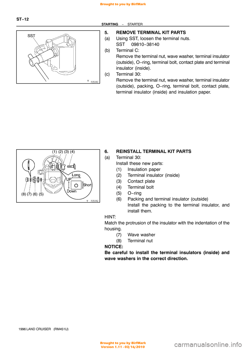
5. REMOVE TERMINAL KIT PARTS
(a) Using SST, loosen the terminal nuts.
SST 09810−38140
(b) Terminal C: Remove the terminal nut, wave washer , terminal insulator
(outside), O− ring, terminal bolt, contact plate and terminal
insulator (inside).
(c) Terminal 30: Remove the terminal nut, wave washer , terminal insulator
(outside), packing, O−ring, terminal bolt, contact plate,
terminal insulator (inside) and insulation paper.
6. REINSTALL TERMINAL KIT PARTS
(a) Terminal 30: Install these new parts:
(1) Insulation paper
(2) Terminal insulator (inside)
(3) Contact plate
(4) Terminal bolt
(5) O−ring
(6) Packing and terminal insulator (outside)Install the packing to the terminal insulator, and
install them.
HINT:
Match the protrusion of the insulator with the indentation of the
housing. (7) Wave washer
(8) Terminal nut
NOTICE:
Be careful to install the terminal insulators (inside) and
wave washers in the correct direction.
Brought to you by BirfMark
Brought to you by BirfMark
Version 1.11 - 03/16/2010
Page 1358 of 1399

V06796
−
STARTING STARTER
ST−13
1996 LAND CRUISER (RM451U)
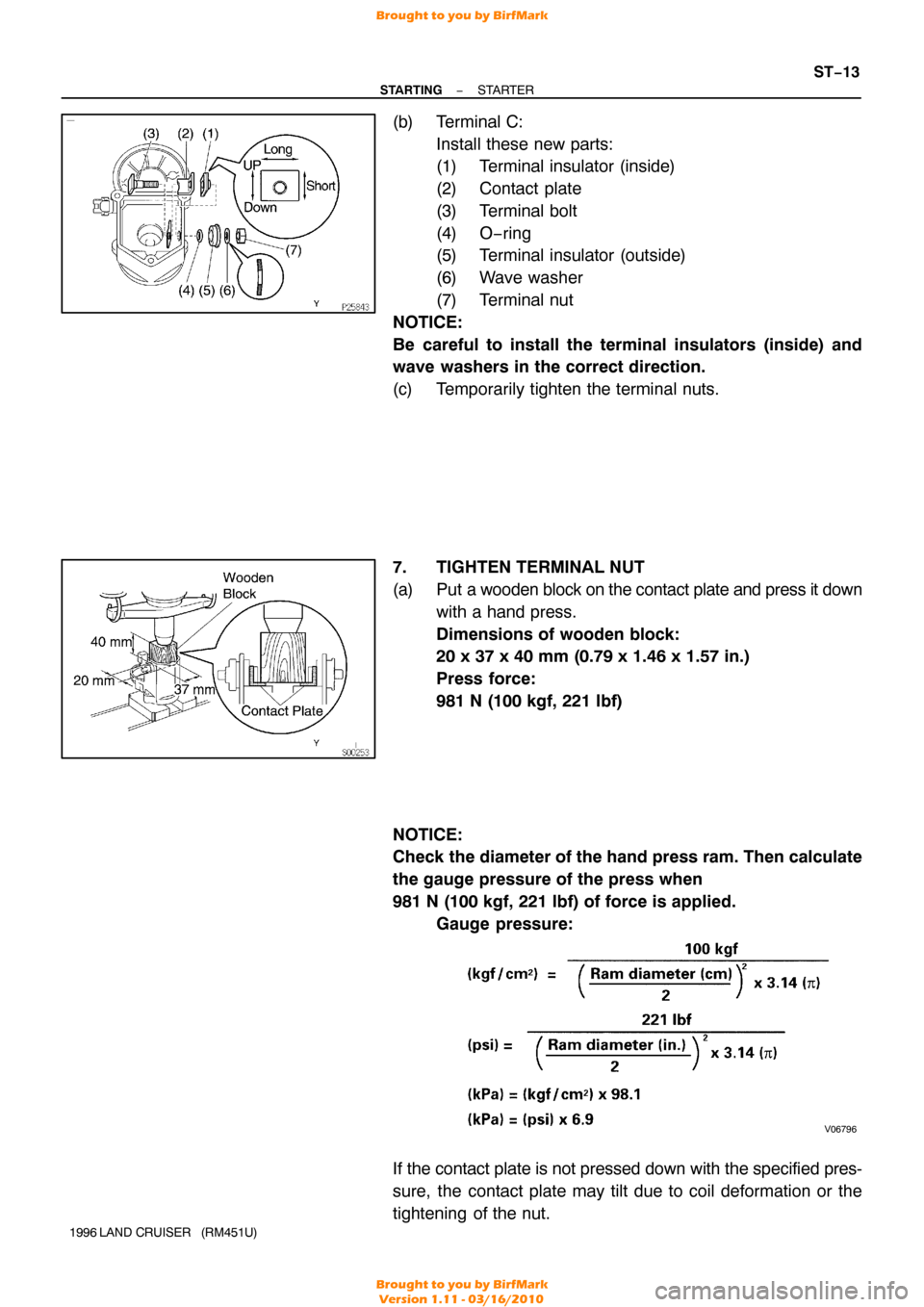
(b) Terminal C:
Install these new parts:
(1) Terminal insulator (inside)
(2) Contact plate
(3) Terminal bolt
(4) O−ring
(5) Terminal insulator (outside)
(6) Wave washer
(7) Terminal nut
NOTICE:
Be careful to install the terminal insulators (inside) and
wave washers in the correct direction.
(c) Temporarily tighten the terminal nuts.
7. TIGHTEN TERMINAL NUT
(a) Put a wooden block on the contact plate and press it down with a hand press.
Dimensions of wooden block:
20 x 37 x 40 mm (0.79 x 1.46 x 1.57 in.)
Press force:
981 N (100 kgf, 221 lbf)
NOTICE:
Check the diameter of the hand press ram. Then calculate
the gauge pressure of the press when
981 N (100 kgf, 221 lbf) of force is applied. Gauge pressure:
If the contact plate is not pressed down with the specified pres-
sure, the contact plate may tilt due to coil deformation or the
tightening of the nut.
Brought to you by BirfMark
Brought to you by BirfMark
Version 1.11 - 03/16/2010