Page 1052 of 1399
R11891
WidthInner
Diam.
AB0158
Battery
SST
R09689
Tires
(5 or more)
RS−28
−
SUPPLEMENTAL RESTRAINT SYSTEM FRONT PASSENGER AIRBAG ASSEMBLY
1996 LAND CRUISER (RM451U)
CAUTION:
If the front passenger airbag assembly is tied down with
too thin wire harness, it may snap. This is highly danger-
ous. Always use a wire harness which is at least 1.25 mm
2
(0.0019 in.2)
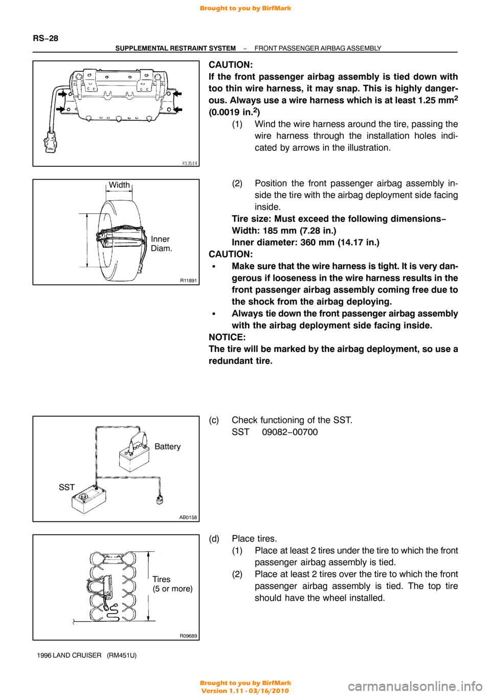
(1) Wind the wire harness around the tire, passing the wire harness through the installation holes indi-
cated by arrows in the illustration.
(2) Position the front passenger airbag assembly in- side the tire with the airbag deployment side facing
inside.
Tire size: Must exceed the following dimensions −
Width: 185 mm (7.28 in.)
Inner diameter: 360 mm (14.17 in.)
CAUTION:
�Make sure that the wire harness is tight. It is very dan-
gerous if looseness in the wire harness results in the
front passenger airbag assembly coming free due to
the shock from the airbag deploying.
�Always tie down the front passenger airbag assembly
with the airbag deployment side facing inside.
NOTICE:
The tire will be marked by the airbag deployment, so use a
redundant tire.
(c) Check functioning of the SST. SST 09082−00700
(d) Place tires. (1) Place at least 2 tires under the tire to which the frontpassenger airbag assembly is tied.
(2) Place at least 2 tires over the tire to which the front passenger airbag assembly is tied. The top tire
should have the wheel installed.
Brought to you by BirfMark
Brought to you by BirfMark
Version 1.11 - 03/16/2010
Page 1108 of 1399
SA2417
Holes
Groore
Z15179
FIPG Width Approx.
1 − 2 mm (0.04 − 0.08 in.)
Z10101
Adhesive
SA2205
SA1979Lock
−
SUSPENSION AND AXLE FRONT DIFFERENTIAL CARRIER
SA−45
1996 LAND CRUISER (RM451U)
30. w/ DIFFERENTIAL LOCK:
INSTALL SHIFT FORK SHAFT
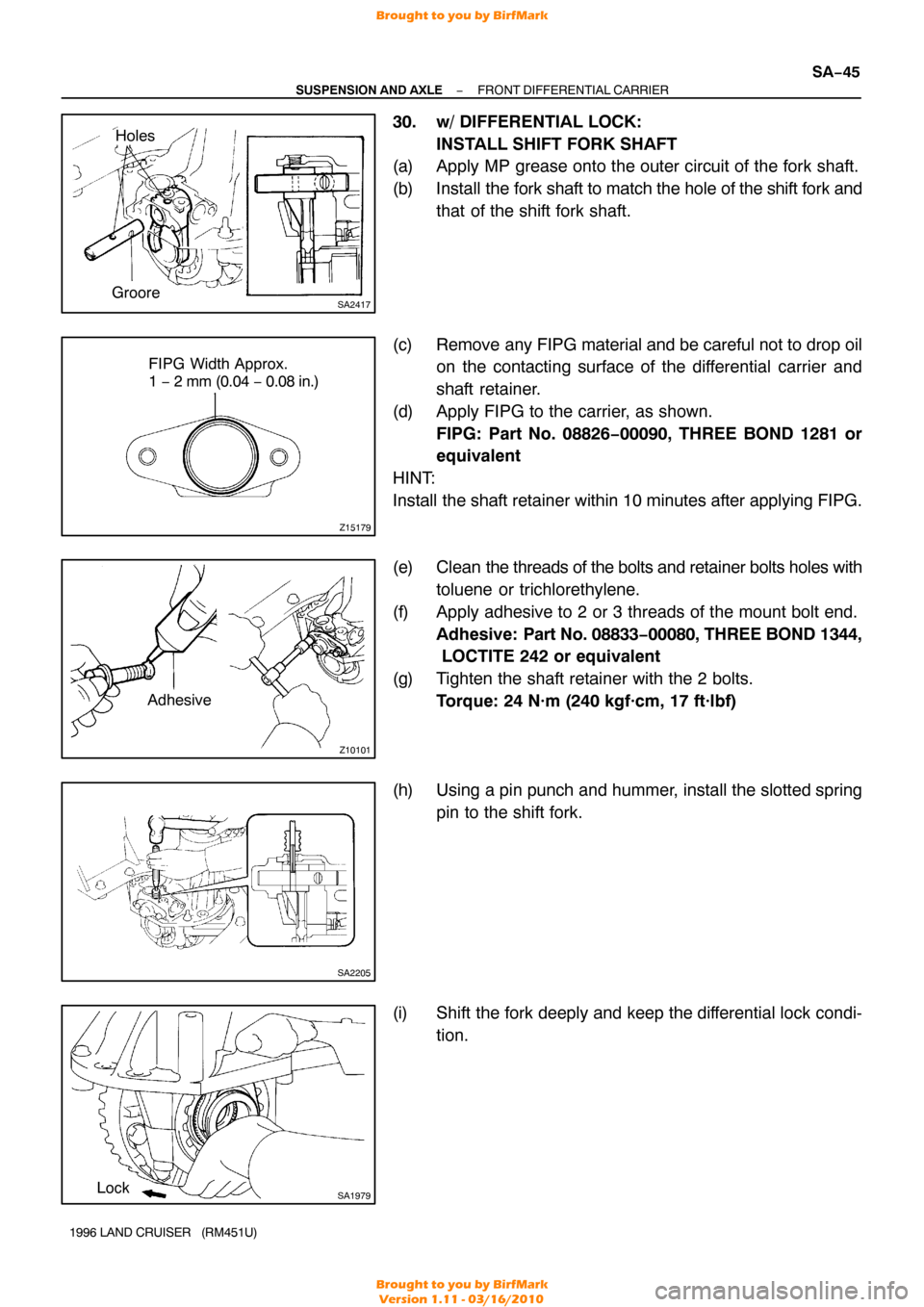
(a) Apply MP grease onto the outer circuit of the fork shaft.
(b) Install the fork shaft to match the hole of the shift fork and
that of the shift fork shaft.
(c) Remove any FIPG material and be careful not to drop oil on the contacting surface of the differential carrier and
shaft retainer.
(d) Apply FIPG to the carrier, as shown. FIPG: Part No. 08826−00090, THREE BOND 1281 or
equivalent
HINT:
Install the shaft retainer within 10 minutes after applying FIPG.
(e) Clean the threads of the bolts and retainer bolts holes with
toluene or trichlorethylene.
(f) Apply adhesive to 2 or 3 threads of the mount bolt end. Adhesive: Part No. 08833 −00080, THREE BOND 1344,
LOCTITE 242 or equivalent
(g) Tighten the shaft retainer with the 2 bolts. Torque: 24 N·m (240 kgf·cm, 17 ft·lbf)
(h) Using a pin punch and hummer, install the slotted spring pin to the shift fork.
(i) Shift the fork deeply and keep the differential lock condi- tion.
Brought to you by BirfMark
Brought to you by BirfMark
Version 1.11 - 03/16/2010
Page 1161 of 1399
Z15220
FIPG Width Approx.
1 − 2 mm (0.04 − 0.08 in.)
SA2129
Z10150
Adhesive
SA−98
−
SUSPENSION AND AXLE REAR DIFFERENTIAL CARRIER
1996 LAND CRUISER (RM451U)
25. RECHECK RING GEAR BACKLASH
Using a dial indicator, measure the ring gear backlash.
Ring gear backlash:
0.15 − 0.20 mm (0.0059 − 0.0079 in.)
26. RECHECK TOOTH CONTACT BETWEEN RING GEAR AND DRIVE PINION
27. CHECK RUNOUT OF COMPANION FLANGE (See
page SA−80 )
28. w/o DIFFERENTIAL LOCK: INSTALL ADJUSTING NUT LOCKS
(a) Install 2 new nut locks on the bearing caps.
(b) Tightening 2 bolts, bend the nut locks. Torque: 13 N·m (130 kgf·cm, 9 ft·lbf)
29. w/ DIFFERENTIAL LOCK: INSTALL ACTUATOR, SHIFT FORK AND SLEEVE
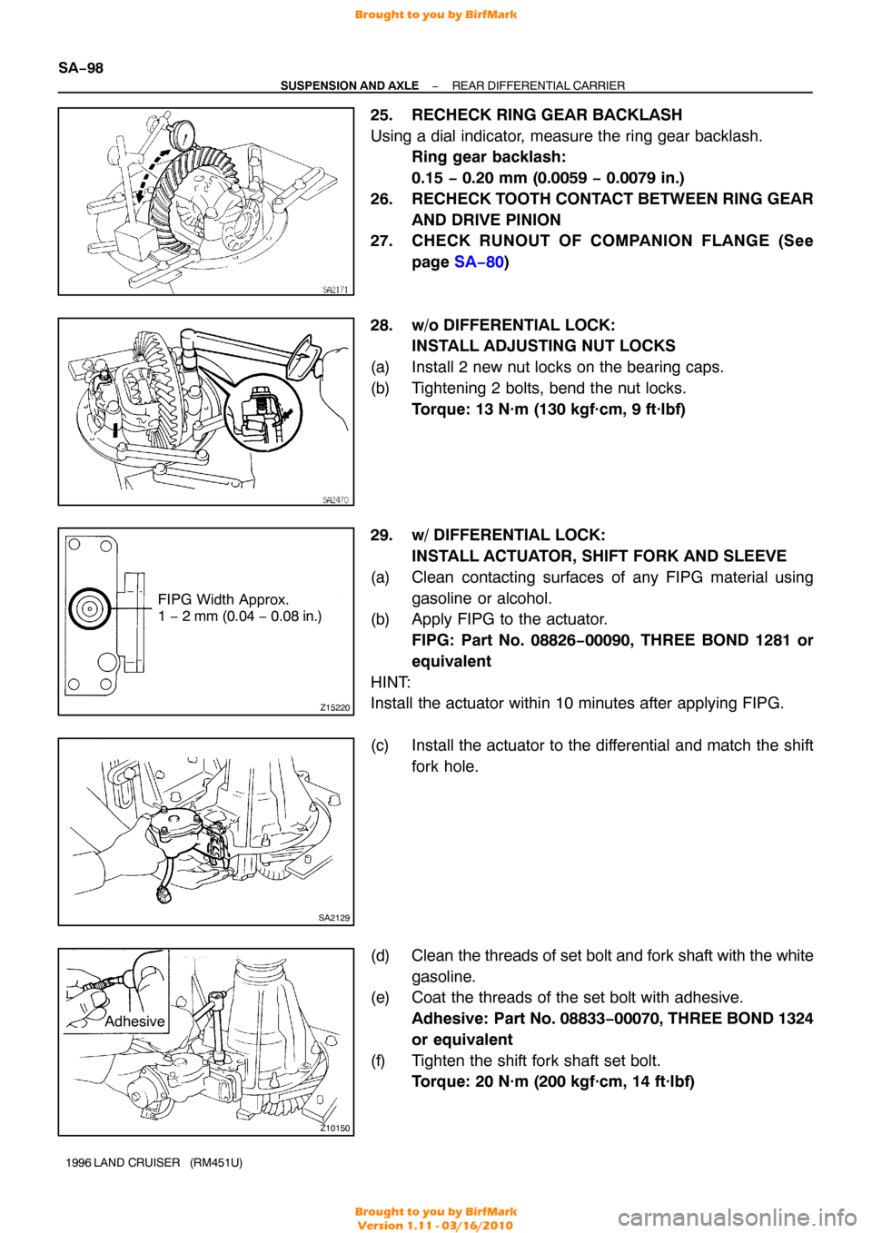
(a) Clean contacting surfaces of any FIPG material using gasoline or alcohol.
(b) Apply FIPG to the actuator.
FIPG: Part No. 08826−00090, THREE BOND 1281 or
equivalent
HINT:
Install the actuator within 10 minutes after applying FIPG.
(c) Install the actuator to the differential and match the shift fork hole.
(d) Clean the threads of set bolt and fork shaft with the white
gasoline.
(e) Coat the threads of the set bolt with adhesive.
Adhesive: Part No. 08833 −00070, THREE BOND 1324
or equivalent
(f) Tighten the shift fork shaft set bolt. Torque: 20 N·m (200 kgf·cm, 14 ft·lbf)
Brought to you by BirfMark
Brought to you by BirfMark
Version 1.11 - 03/16/2010
Page 1162 of 1399
SA2133
SA2131
Z15219
FIPG Width Approx.
1 − 2 mm (0.04 − 0.08 in.)
−
SUSPENSION AND AXLE REAR DIFFERENTIAL CARRIER
SA−99
1996 LAND CRUISER (RM451U)
(g) Engage the sleeve with the dog clutch of the differential
case.
(h) Tighten the 4 bolts. Torque: 24 N·m (240 kgf·cm, 17 ft·lbf)
30. w/ DIFFERENTIAL LOCK: INSTALL COVER
(a) Clean contacting surfaces of any FIPG material using gasoline or alcohol.
(b) Apply FIPG to the cover.
FIPG: Part No. 08826−00090, THREE BOND 1281 or
equivalent
HINT:
Install the cover within 10 minutes after applying FIPG.
(c) Tighten the 3 bolts. Torque: 18 N·m (185 kgf·cm, 13 ft·lbf)
31. w/ DIFFERENTIAL LOCK: INSTALL INDICATOR SWITCH
Install the indicator switch with a new gasket.
Torque: 40 N·m (410 kgf·cm, 30 ft·lbf)
Brought to you by BirfMark
Brought to you by BirfMark
Version 1.11 - 03/16/2010
Page 1173 of 1399
Z15220
FIPG Width Approx.
1 − 2 mm (0.04 − 0.08 in.)
Z07262Adhesive
SA2620
SA−11 0
−
SUSPENSION AND AXLE DIFFERENTIAL LOCKING SYSTEM
1996 LAND CRUISER (RM451U)
(g) Connect the connector and tube.
HINT:
�The depth of the insertion of the bleeder tube into the
hose is approx. 15 mm (0.59 in.).
�Take care that water or the equivalent will not adhere to
the connector and hose.
(h) Cancel the front differential lock.
With the ignition switch ON, turn the differential lock con-
trol switch to OFF to cancel the differential lock.
2. INSTALL REAR ACTUATOR
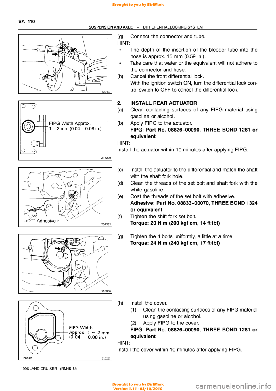
(a) Clean contacting surfaces of any FIPG material using gasoline or alcohol.
(b) Apply FIPG to the actuator. FIPG: Part No. 08826−00090, THREE BOND 1281 or
equivalent
HINT:
Install the actuator within 10 minutes after applying FIPG.
(c) Install the actuator to the differential and match the shaft with the shaft fork hole.
(d) Clean the threads of the set bolt and shaft fork with the white gasoline.
(e) Coat the threads of the set bolt with adhesive.
Adhesive: Part No. 08833 −00070, THREE BOND 1324
or equivalent
(f) Tighten the shift fork set bolt. Torque: 20 N·m (200 kgf·cm, 14 ft·lbf)
(g) Tighten the 4 bolts uniformly, a little at a time. Torque: 24 N·m (240 kgf·cm, 17 ft·lbf)
(h) Install the cover. (1) Clean the contacting surfaces of any FIPG material
using gasoline or alcohol.
(2) Apply FIPG to the cover.
FIPG: Part No. 08826−00090, THREE BOND 1281 or
equivalent
HINT:
Install the cover within 10 minutes after applying FIPG.
Brought to you by BirfMark
Brought to you by BirfMark
Version 1.11 - 03/16/2010
Page 1305 of 1399
SS1EO−04
SS−4
−
SERVICE SPECIFICATIONS ENGINE MECHANICAL
127
Author�: Date�:
1996 LAND CRUISER (RM451U)
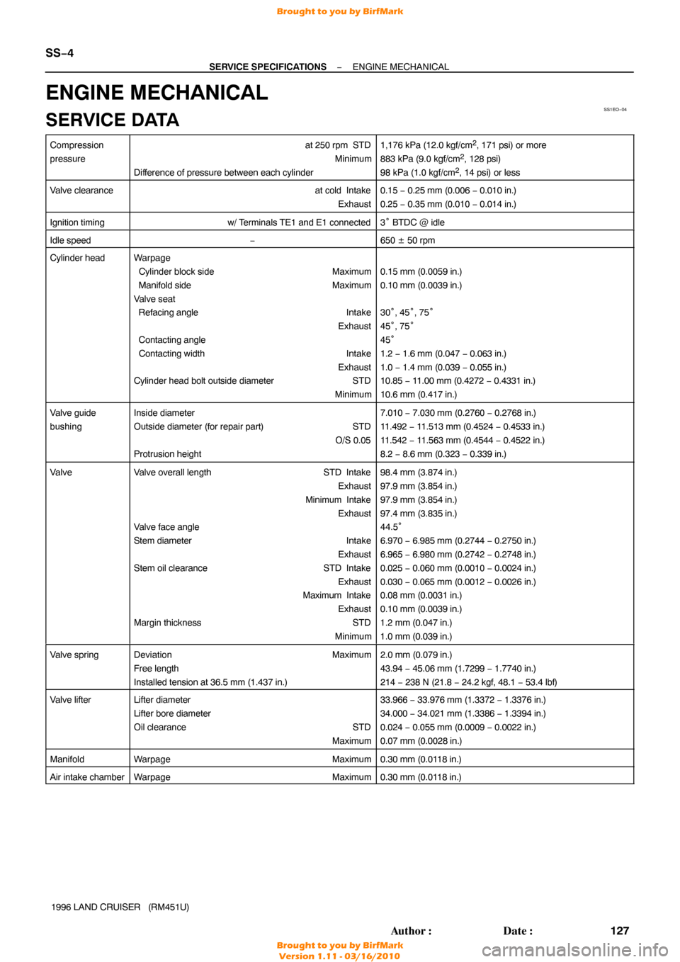
ENGINE MECHANICAL
SERVICE DATA
Compression
pressureat 250 rpm STD
Minimum
Difference of pressure between each cylinder1,176 kPa (12.0 kgf/cm2, 171 psi) or more
883 kPa (9.0 kgf/cm2, 128 psi)
98 kPa (1.0 kgf/cm2, 14 psi) or less
Valve clearanceat cold Intake Exhaust0.15 − 0.25 mm (0.006 − 0.010 in.)
0.25 − 0.35 mm (0.010 − 0.014 in.)
Ignition timingw/ Terminals TE1 and E1 connected3° BTDC @ idle
Idle speed−650 ± 50 rpm
Cylinder headWarpage
Cylinder block side Maximum
Manifold side Maximum
Valve seat
Refacing angle Intake
Exhaust
Contacting angle
Contacting width Intake
Exhaust
Cylinder head bolt outside diameter STD
Minimum
0.15 mm (0.0059 in.)
0.10 mm (0.0039 in.)
30°, 45° , 75°
45 °, 75°
45 °
1.2 − 1.6 mm (0.047 − 0.063 in.)
1.0 − 1.4 mm (0.039 − 0.055 in.)
10.85 − 11.00 mm (0.4272 − 0.4331 in.)
10.6 mm (0.417 in.)
Valve guide
bushingInside diameter
Outside diameter (for repair part) STD O/S 0.05
Protrusion height7.010 − 7.030 mm (0.2760 − 0.2768 in.)
11.492 − 11.513 mm (0.4524 − 0.4533 in.)
11.542 − 11.563 mm (0.4544 − 0.4522 in.)
8.2 − 8.6 mm (0.323 − 0.339 in.)
ValveValve overall length STD Intake
Exhaust
Minimum Intake Exhaust
Valve face angle
Stem diameter Intake
Exhaust
Stem oil clearance STD Intake
Exhaust
Maximum Intake
Exhaust
Margin thickness STD
Minimum98.4 mm (3.874 in.)
97.9 mm (3.854 in.)
97.9 mm (3.854 in.)
97.4 mm (3.835 in.)
44.5 °
6.970 − 6.985 mm (0.2744 − 0.2750 in.)
6.965 − 6.980 mm (0.2742 − 0.2748 in.)
0.025 − 0.060 mm (0.0010 − 0.0024 in.)
0.030 − 0.065 mm (0.0012 − 0.0026 in.)
0.08 mm (0.0031 in.)
0.10 mm (0.0039 in.)
1.2 mm (0.047 in.)
1.0 mm (0.039 in.)
Valve springDeviation Maximum
Free length
Installed tension at 36.5 mm (1.437 in.)2.0 mm (0.079 in.)
43.94 − 45.06 mm (1.7299 − 1.7740 in.)
214 − 238 N (21.8 − 24.2 kgf, 48.1 − 53.4 lbf)
Valve lifterLifter diameter
Lifter bore diameter
Oil clearance STD
Maximum33.966 − 33.976 mm (1.3372 − 1.3376 in.)
34.000 − 34.021 mm (1.3386 − 1.3394 in.)
0.024 − 0.055 mm (0.0009 − 0.0022 in.)
0.07 mm (0.0028 in.)
ManifoldWarpage Maximum0.30 mm (0.0118 in.)
Air intake chamberWarpageMaximum0.30 mm (0.0118 in.)
Brought to you by BirfMark
Brought to you by BirfMark
Version 1.11 - 03/16/2010