Page 855 of 1399

13. DISCONNECT ENGINE WIRE AND HEATER VALVE
FROM COWL PANEL
(a) Remove the 2 bolts and disconnect the engine wire and
ground str")
EM−70
−
ENGINE MECHANICAL ENGINE UNIT
1996 LAND CRUISER (RM451U)
13. DISCONNECT ENGINE WIRE AND HEATER VALVE
FROM COWL PANEL
(a) Remove the 2 bolts and disconnect the engine wire and
ground strap.
(b) Remove the 2 bolts and disconnect the heater valve.
14. DISCONNECT BRAKE BOOSTER VACUUM HOSE
15. DISCONNECT EVAP HOSE
16. DISCONNECT FUEL HOSES
(a) Disconnect the fuel return hose.
(b) Remove the union bolt and 2 gaskets, and disconnect the
fuel inlet hose from the fuel filter.
17. DISCONNECT WIRES AND CONNECTORS
(a) Disconnect the 2 heated oxygen sensor connectors.
(b) Disconnect the DLC1 clamp.
(c) Disconnect the 2 oil pressure gauge connectors.
(d) Disconnect the generator wire and connector.
(e) Disconnect the connector on the intake manifold from the
fender apron.
(f) Disconnect the high−tension cord from the ignition coil.
(g) Disconnect the ground strap from the No. 1 engine hang-
er.
(h) Disconnect the ground strap from the air intake chamber.
(i) Disconnect the starter wire.
(j) Disconnect the ground cable from the cylinder block.
18. DISCONNECT A/C COMPRESSOR AND BRACKET
(a) Loosen the idler pulley nut and adjusting bolt, and remove
the drive belt.
(b) Remove the 4 mounting bolts, and disconnect the com-
pressor from the bracket.
HINT:
Put aside the compressor, and suspend it.
(c) Remove the 5 bolts and A/C compressor bracket.
19. REMOVE RADIATOR PIPE
(a) Remove the 2 nuts holding the radiator pipe to the No. 1 oil pan.
(b) Disconnect the No. 2 radiator hose from the water inlet and remove the radiator pipe.
Brought to you by BirfMark
Brought to you by BirfMark
Version 1.11 - 03/16/2010
Page 865 of 1399

19. CONNECT ENGINE WIRE TO CABIN
(a) Push in the engine wire through the cowl panel.
(b) Connect the connectors.
(1) Connect the")
EM−80
−
ENGINE MECHANICAL ENGINE UNIT
1996 LAND CRUISER (RM451U)
19. CONNECT ENGINE WIRE TO CABIN
(a) Push in the engine wire through the cowl panel.
(b) Connect the connectors.
(1) Connect the 3 connectors to the ECM.
(2) Connect the 2 connectors to the cowl wire.
(c) Connect the A/C amplifier with the screw.
(d) Install the speaker panel with the screw.
(e) Install the glove compartment door with the 2 screws.
20. CONNECT PS RETURN HOSE
Connect the return hose to the PS reservoir tank.
21. CONNECT PS PRESSURE HOSE
Connect the PS pressure hose with 2 new gaskets and the
union bolt. Torque: 56 N·m (575 kgf·cm, 42 ft·lbf)
22. INSTALL RADIATOR PIPE
(a) Connect the No. 2 radiator hose to the water inlet.
(b) Install the 2 nuts holding the radiator pipe to the No. 1 oil pan.
Torque: 21 N·m (210 kgf·cm, 15 ft·lbf)
23. INSTALL A/C COMPRESSOR AND BRACKET
(a) Install the A/C compressor bracket with the 5 bolts.
Torque: 37 N·m (375 kgf·cm, 27 ft·lbf)
(b) Install the A/C compressor with the 4 bolts. Torque: 25 N·m (250 kgf·cm, 18 ft·lbf)
(c) Install and adjust the drive belt (See page CH−2).
24. CONNECT WIRES AND CONNECTORS
(a) Connect the 2 heated oxygen sensor connectors.
(b) Connect the DLC1 clamp.
(c) Connect the 2 oil pressure gauge connectors.
(d) Connect the generator wire and connector.
(e) Connect the connector on the intake manifold to the fend-
er apron.
(f) Connect the high −tension cord to the ignition coil.
(g) Connect the ground strap to the No. 1 engine hanger.
(h) Connect the ground strap to the air intake chamber.
(i) Connect the starter wire.
(j) Connect the ground cable to the cylinder block.
25. CONNECT FUEL HOSES
(a) Connect the fuel inlet hose to the fuel filter with 2 new gas-
kets and the union bolt.
Torque: 29 N·m (300 kgf·cm, 22 ft·lbf)
(b) Connect the fuel return hose.
Brought to you by BirfMark
Brought to you by BirfMark
Version 1.11 - 03/16/2010
Page 937 of 1399

ENGINE
INSPECTION
HINT:
Inspect these items when the engine is cold.
1. INSPECT DRIVE BELT (See page CH")
MA04U−01
P04771
−
MAINTENANCE ENGINE
MA−5
45
Author�: Date�:
1996 LAND CRUISER (RM451U)
ENGINE
INSPECTION
HINT:
Inspect these items when the engine is cold.
1. INSPECT DRIVE BELT (See page CH−2)
2. INSPECT AIR FILTER
(a) Visually check that the air cleaner element is not exces- sively dirty, damaged or oily.
If necessary, replace the air cleaner element.
(b) Clean the element with compressed air. First blow from the inside thoroughly, then blow off the
outside of the element.
3. REPLACE AIR FILTER
Replace the air cleaner element with a new one.
4. REPLACE SPARK PLUGS (See page IG−1 )
5. REPLACE ENGINE OIL AND OIL FILTER (See page LU−2)
6. REPLACE ENGINE COOLANT (See page CO−2)
7. INSPECT CHARCOAL CANISTER (See page EC−6 )
8. REPLACE GASKET IN FUEL TANK CAP (See page
EC−6)
9. INSPECT FUEL LINES AND CONNECTIONS (See page EC−6)
10. INSPECT EXHAUST PIPES AND MOUNTINGS
Visually inspect the p ipes, hangers and connections for severe
corrosion, leaks or damage.
11. ADJUST VALVE CLEARANCE (See page EM−4)
Brought to you by BirfMark
Brought to you by BirfMark
Version 1.11 - 03/16/2010
Page 1196 of 1399

REMOVAL
CAUTION:
Do not smoke or work near an open flame when working on
the fuel pump.
1. REMOVE SECOND SEATS
Torque: 39 N·m (400 kg")
SF1EH−02
−
SFI FUEL PUMP
SF−11
1996 LAND CRUISER (RM451U)
REMOVAL
CAUTION:
Do not smoke or work near an open flame when working on
the fuel pump.
1. REMOVE SECOND SEATS
Torque: 39 N·m (400 kgf·cm, 29 ft·lbf)
2. REMOVE SCUFF PLATE
3. REMOVE SIDE GARNISH
4. REMOVE STEP PLATE
5. DISCONNECT FLOOR MATS
6. REMOVE FLOOR SERVICE HOLE COVER
Remove the 3 screws and service hole cover.
7. DISCONNECT FUEL PIPE AND HOSE FROM FUEL
PUMP BRACKET
CAUTION:
Remove the fuel filter cap to prevent the fuel from flowing
out.
(a) Disconnect the fuel pump and sender gauge connector.
HINT:
At the time of installation, plaese refer to the following items.
Check for fuel leakage.
(b) Remove the union bolt and gaskets, and disconnect the outlet pipe from the pump bracket.
Torque: 29 N·m (300 kgf·cm, 22 ft·lbf)
(c) Disconnect the return hose from the pump bracket.
8. REMOVE FUEL PUMP BRACKET ASSEMBLY FROM
FUEL TANK
(a) Remove the 8 bolts.
Torque: 3.9 N·m (40 kgf·cm, 35 in.·lbf)
(b) Pull out the pump bracket assembly.
NOTICE:
�Do not damage the fuel pump filter.
�Be careful that the arm of the sender gauge should
not bent.
(c) Remove the gasket from the pump bracket.
Brought to you by BirfMark
Brought to you by BirfMark
Version 1.11 - 03/16/2010
Page 1198 of 1399
SF1EI−03
−
SFI FUEL PUMP
SF−13
1996 LAND CRUISER (RM451U)
DISASSEMBLY
1. REMOVE FUEL PUMP FROM FUEL PUMP BRACKET
(a) Pull off the lower side of the fuel pump from the pump
bracket.
(b) Disconnect the fuel pump connector.
(c) Disconnect the fuel hose from the fuel pump, and remove
the fuel pump.
(d) Remove the rubber cushion from the fuel pump.
2. REMOVE FUEL PUMP FILTER FROM FUEL PUMP
(a) Using a small screwdriver, remove the clip.
HINT:
At the time of installation, plaese refer to the following items.
install the pump filter with a new clip.
(b) Pull out the pump filter.
3. REMOVE FUEL SENDER GAUGE FROM FUEL PUMP BRACKET
(a) Remove the 3 screws and disconnect the lead wires from
the pump bracket.
(b) Remove the 2 screws and sender gauge.
Brought to you by BirfMark
Brought to you by BirfMark
Version 1.11 - 03/16/2010
Page 1203 of 1399
SF1EL−01
SF−18
−
SFI FUEL FILTER
646
Author�: Date�:
1996 LAND CRUISER (RM451U)
FUEL FILTER
COMPONENTS
Brought to you by BirfMark
Brought to you by BirfMark
Version 1.11 - 03/16/2010
Page 1215 of 1399
SF1EO−03
−
SFI INJECTOR
SF−29
1996 LAND CRUISER (RM451U)
INSPECTION
1. INSPECT INJECTOR INJECTION
CAUTION:
Keep injector clean of sparks during the test.
(a) Connect SST (union and hose) to the fuel filter outlet with
the 2 gaskets and union bolt.
SST 09268−41046 (90405 −09015)
Torque: 29 N·m (300 kgf·cm, 22 ft·lbf)
(b) Remove the fuel pressure regulator (See page SF−21).
(c) Install the O−ring to the fuel inlet of pressure regulator.
(d) Connect SST (hose) to the fuel inlet of the pressure regu-
lator with SST (union).
SST 09268−41046 (09268 −41091)
Torque: 25 N·m (250 kgf·cm, 18 ft·lbf)
(e) Connect the fuel return hose to the fuel outlet of the pres-
sure regulator.
Brought to you by BirfMark
Brought to you by BirfMark
Version 1.11 - 03/16/2010
Page 1245 of 1399
SF1F9−01
−
SFI VSV FOR FUEL PRESSURE CONTROL
SF−59
687
Author�: Date�:
1996 LAND CRUISER (RM451U)
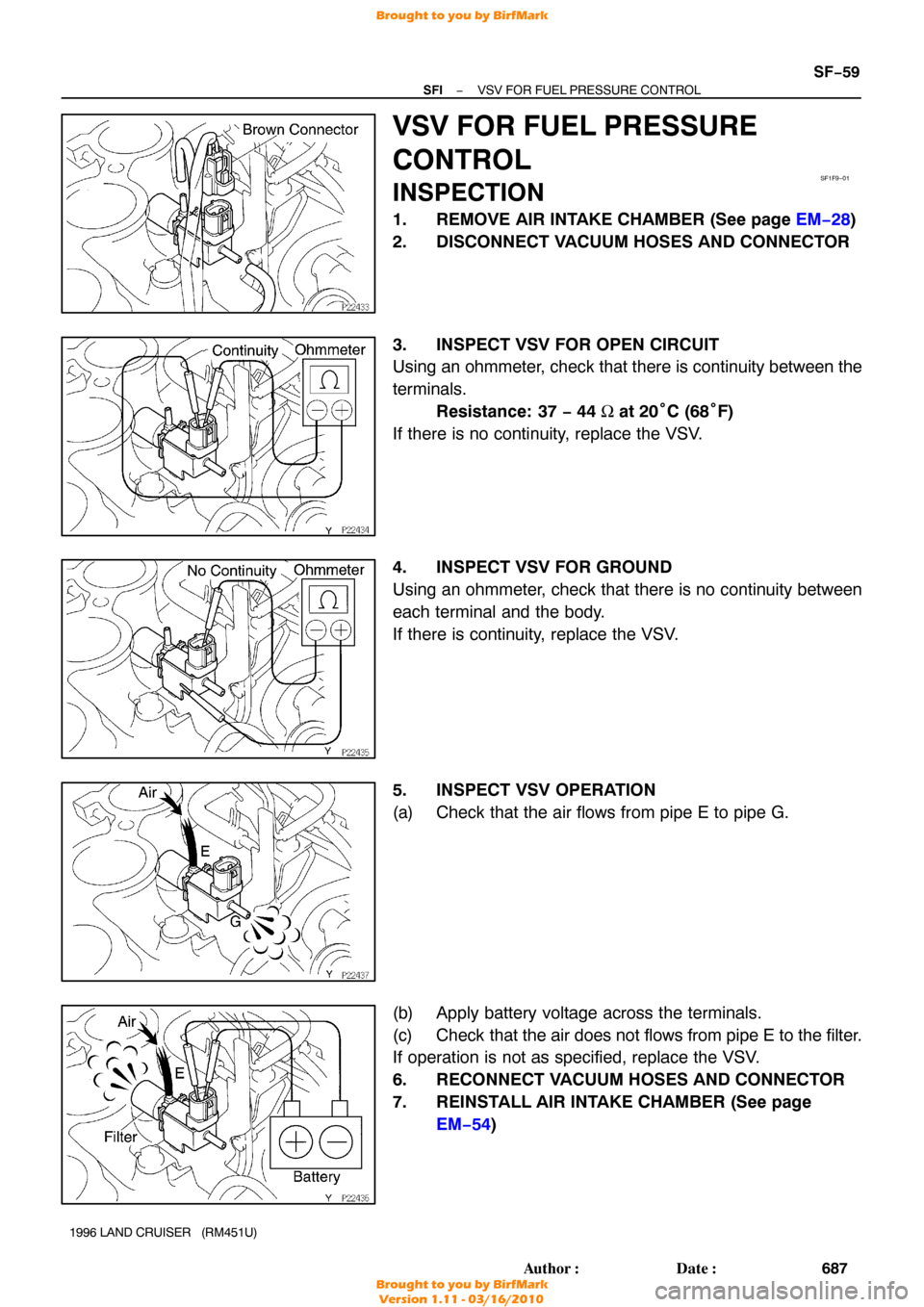
VSV FOR FUEL PRESSURE
CONTROL
INSPECTION
1. REMOVE AIR INTAKE CHAMBER (See page EM−28 )
2. DISCONNECT VACUUM HOSES AND CONNECTOR
3. INSPECT VSV FOR OPEN CIRCUIT
Using an ohmmeter, check that there is continuity between the
terminals. Resistance: 37 − 44 Ω at 20° C (68°F)
If there is no continuity, replace the VSV.
4. INSPECT VSV FOR GROUND
Using an ohmmeter, check that there is no continuity between
each terminal and the body.
If there is continuity, replace the VSV.
5. INSPECT VSV OPERATION
(a) Check that the air flows from pipe E to pipe G.
(b) Apply battery voltage across the terminals.
(c) Check that the air does not flows from pipe E to the filter.
If operation is not as specified, replace the VSV.
6. RECONNECT VACUUM HOSES AND CONNECTOR
7. REINSTALL AIR INTAKE CHAMBER (See page EM−54 )
Brought to you by BirfMark
Brought to you by BirfMark
Version 1.11 - 03/16/2010

DISASSEMBLY
1. REMOVE FUEL PUMP FROM FUEL PUMP BRACKET
(a) Pull off the lower side of the fuel pump from the pump
bracket.
(b) Disconn")


INSPECTION
1. INSPECT INJECTOR INJECTION
CAUTION:
Keep injector clean of sparks during the test.
(a) Connect SST (union and hose) to t")