Page 786 of 1399

EM1E0−04
−
ENGINE MECHANICAL CO/HC
EM−1
504
Author�: Date�:
1996 LAND CRUISER (RM451U)
CO/HC
INSPECTION
HINT:
This check is used only to det ermine whether or not the idle CO/
HC complies with regulations.
1. INITIAL CONDITIONS
(a) Engine at normal operating temperature
(b) Air cleaner installed
(c) All pipes and hoses of air induction system connected
(d) All accessories switched OFF
(e) All vacuum lines properly connected
HINT:
All vacuum hoses for EGR systems, etc. should be properly
connected.
(f) SFI system wiring connectors fully plugged
(g) Ignition timing set correctly
(h) Transmission in neutral position
(i) Tachometer and CO/HC meter calibrated by hand
2. START ENGINE
3. RACE ENGINE AT 2,500 RPM FOR APPROX. 180 SE-
CONDS
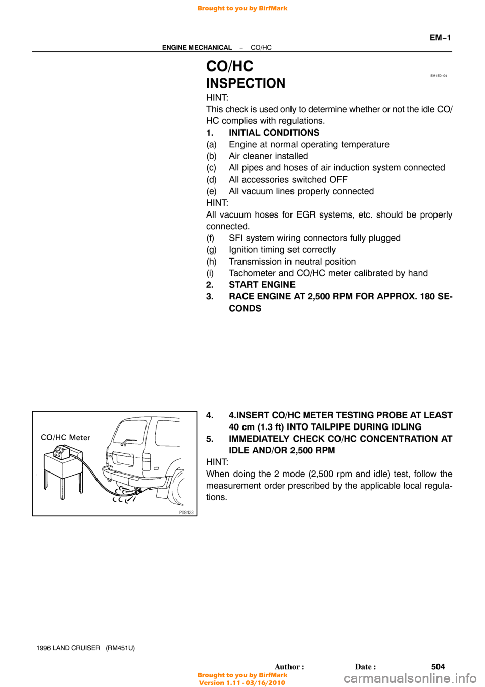
4. 4.INSERT CO/HC METER TESTING PROBE AT LEAST
40 cm (1.3 ft) INTO TAILPIPE DURING IDLING
5. IMMEDIATELY CHECK CO/HC CONCENTRATION AT IDLE AND/OR 2,500 RPM
HINT:
When doing the 2 mode (2,500 rpm and idle) test, follow the
measurement order prescribed by the applicable local regula-
tions.
Brought to you by BirfMark
Brought to you by BirfMark
Version 1.11 - 03/16/2010
Page 796 of 1399
EM0KU−05
−
ENGINE MECHANICAL IDLE SPEED
EM−11
514
Author�: Date�:
1996 LAND CRUISER (RM451U)
IDLE SPEED
INSPECTION
1. INITIAL CONDITIONS
(a) Engine at normal operating temperature.
(b) Air cleaner installed.
(c) All pipes and hoses of air induction system connected.
(d) All accessories switched OFF.
(e) All vacuum lines properly connected.
HINT:
All vacuum hoses for EGR system, etc. should be properly connected.
(f) SFI system wiring connectors fully plugged.
(g) Ignition timing set correctly.
(h) Transmission in neutral position.
(i) Air conditioning switched OFF.
2. CONNECT TOYOTA HAND−HELD TESTER OR OBD II SCAN TOOL (See page EM−10)
3. INSPECT IDLE SPEED
(a) Race the engine speed at 2,500 rpm for approx. 90 seconds.
(b) Check the idle speed.
Idle speed: 650 ± 50 rpm
If the idle speed is not as specified, check the IAC valve.
4. DISCONNECT TOYOTA HAND−HELD TESTER OR OBD II SCAN TOOL
Brought to you by BirfMark
Brought to you by BirfMark
Version 1.11 - 03/16/2010
Page 814 of 1399

−
ENGINE MECHANICAL CYLINDER HEAD
EM−29
1996 LAND CRUISER (RM451U)
16. DISCONNECT PS RESERVOIR TANK
Remove the 3 bolts and disconnect the reservoir tank.
17. DISCONNECT RADIATOR INLET HOSE
18. DISCONNECT NO. 3 WATER BYPASS HOSE
19. REMOVE GENERATOR (See page CH−8 )
20. REMOVE THROTTLE BODY (See page SF−45)
21. REMOVE OIL DIPSTICKS AND GUIDES FOR ENGINE AND TRANSMISSION
(a) Remove the 2 mounting bolts.
(b) Pull out the dipstick together with dipstick guide.
(c) Remove the O−ring from the dipstick guide.
22. REMOVE INTAKE MANIFOLD STAY
Remove the 2 bolts and intake manifold stay.
23. DISCONNECT FUEL INLET HOSE
Remove the union bolt and 2 gaskets, and disconnect the fuel
inlet hose from the fuel filter.
24. DISCONNECT ENGINE WIRE
(a) Disconnect the connectors. (1) Disconnect the ECT sender gauge connector.
(2) Disconnect the ECT cut switch connector.
(3) Disconnect the ECT sensor connector.
(4) Disconnect the knock sensor connector.
(5) Disconnect the crankshaft position sensor connec-tor.
(6) Remove the bolt and disconnect the engine wire from the cylinder block.
Brought to you by BirfMark
Brought to you by BirfMark
Version 1.11 - 03/16/2010
Page 815 of 1399

EM−30
−
ENGINE MECHANICAL CYLINDER HEAD
1996 LAND CRUISER (RM451U)
(b) Disconnect the connectors.
(1) Disconnect the knock sensor connector.
(2) Disconnect the oil level sensor connector.
(3) Disconnect the 2 connectors from the transmission.
(4) Disconnect the starter connector.
(c) Disconnect the 2 heated oxygen sensor connectors.
(d) Disconnect the PNP switch connector.
(e) Remove the 2 bolts and disconnect the engine wire from the intake manifold and cylinder block.
(f) Disconnect the PCV hose from the PCV valve.
(g) Remove the bolt holding the engine wire to the intake manifold.
(h) Disconnect the connectors. (1) Disconnect the connector for the emission controlvalve set assembly.
(2) Disconnect the 3 injector connectors.
(i) Disconnect the engine wire clamp.
(j) Disconnect the engine wire clamp.
(k) Disconnect the connectors.
(1) Disconnect the 3 injector connectors.
(2) Disconnect the EGR gas temp. sensor connector.
(l) Disconnect the clamp of the No. 6 injector wire from the bracket.
(m) Disconnect the engine wire from the cylinder head and in-
take manifold.
25. DISCONNECT NO. 2 WATER BYPASS PIPE
Remove the 3 bolts, and disconnect the bypass pipe from the
cylinder head.
Brought to you by BirfMark
Brought to you by BirfMark
Version 1.11 - 03/16/2010
Page 847 of 1399

EM−62
−
ENGINE MECHANICAL CYLINDER HEAD
1996 LAND CRUISER (RM451U)
(h) Connect the engine wire to the intake manifold and cylin-
der block with the 2 bolts.
(i) Connect the PNP switch connector.
(j) Connect the 2 heated oxygen sensor connectors.
(k) Connect the connectors.
(1) Connect the Knock sensor connector.
(2) Connect the oil level sensor connector.
(3) Connect the 2 connectors to tthe ransmission.
(4) Connect the starter connector.
(l) Connect the engine wire to the cylinder block with the bolt.
(m) Connect the connectors.
(1) Connect the ECT sender gauge connector.
(2) Connect the ECT cut switch connector.
(3) Connect the ECT sensor connector.
(4) Connect the knock sensor connector.
(5) Connect the crankshaft position sensor connector.
19. CONNECT FUEL INLET HOSE
Connect the fuel inlet hose to the fuel filter with 2 new gaskets
and the union bolt. Torque: 29 N·m (300 kgf·cm, 22 ft·lbf)
20. INSTALL INTAKE MANIFOLD STAY
Install the intake manifold stay with the 2 bolts. Torque: 36 N·m (360 kgf·cm, 26 ft·lbf)
21. INSTALL OIL DIPSTICKS AND GUIDES FOR ENGINE AND TRANSMISSION
(a) Install a new O−ring to the dipstick guide.
(b) Apply a light coat of engine oil on the O −ring.
(c) Push in the dipstick guide into the guide hole of the oil pan.
(d) Install the dipstick guide with the 2 bolts. Torque: 20 N·m (200 kgf·cm, 14 ft·lbf)
22. INSTALL THROTTLE BODY (See page SF−48)
23. INSTALL GENERATOR AND DRIVE BELTS (See page CH−19 )
Brought to you by BirfMark
Brought to you by BirfMark
Version 1.11 - 03/16/2010
Page 858 of 1399

−
ENGINE MECHANICAL ENGINE UNIT
EM−73
1996 LAND CRUISER (RM451U)
(g) Disconnect the 3 connectors.
(h) Remove the 10 bolts and the transfer shift lever boot and
transmission shift lever assembly.
(i) Pull out the pin and disconnect the shift rod.
(j) Remove the 4 bolts, hose clamp and the transfer shift le- ver.
26. REMOVE FRONT EXHAUST PIPE
(a) Disconnect the heated oxygen sensor connector.
(b) Remove the 2 nuts and 2 bolts holding the front exhaust pipe to the rear TWC.
(c) Disconnect the front exhaust pipe, and remove the gas- ket.
(d) Loosen the clamp bolt and disconnect the clamp from the
No.1 support bracket.
(e) Remove the 2 bolts and No. 1 support bracket.
(f) Remove the 4 nuts, front exhaust pipe and 2 gaskets.
27. DISCONNECT GROUND STRAP FROM HEAT INSULA-
TOR
28. PLACE JACK UNDER TRANSMISSION
Be sure to put a wooden block between the jack and the trans-
mission oil pan to prevent damage.
Brought to you by BirfMark
Brought to you by BirfMark
Version 1.11 - 03/16/2010
Page 859 of 1399

EM−74
−
ENGINE MECHANICAL ENGINE UNIT
1996 LAND CRUISER (RM451U)
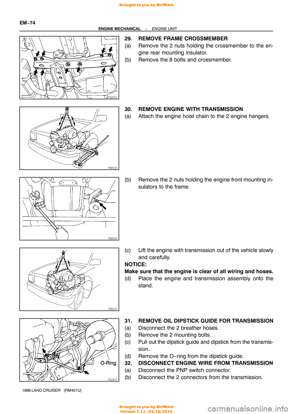
29. REMOVE FRAME CROSSMEMBER
(a) Remove the 2 nuts holding the crossmember to the en-
gine rear mounting insulator.
(b) Remove the 8 bolts and crossmember.
30. REMOVE ENGINE WITH TRANSMISSION
(a) Attach the engine hoist chain to the 2 engine hangers.
(b) Remove the 2 nuts holding the engine front mounting in- sulators to the frame.
(c) Lift the engine with transmission out of the vehicle slowly
and carefully.
NOTICE:
Make sure that the engine is clear of all wiring and hoses.
(d) Place the engine and transmission assembly onto the stand.
31. REMOVE OIL DIPSTICK GUIDE FOR TRANSMISSION
(a) Disconnect the 2 breather hoses.
(b) Remove the 2 mounting bolts.
(c) Pull out the dipstick guide and dipstick from the transmis- sion.
(d) Remove the O−ring from the dipstick guide.
32. DISCONNECT ENGINE WIRE FROM TRANSMISSION
(a) Disconnect the PNP switch connector.
(b) Disconnect the 2 connectors from the transmission.
Brought to you by BirfMark
Brought to you by BirfMark
Version 1.11 - 03/16/2010
Page 862 of 1399

−
ENGINE MECHANICAL ENGINE UNIT
EM−77
1996 LAND CRUISER (RM451U)
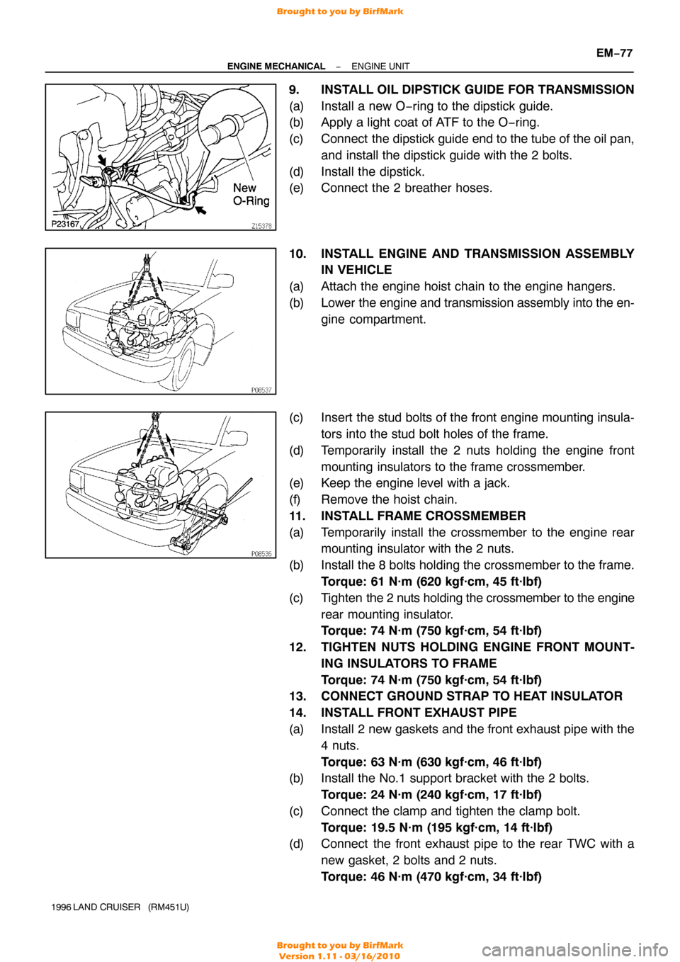
9. INSTALL OIL DIPSTICK GUIDE FOR TRANSMISSION
(a) Install a new O−ring to the dipstick guide.
(b) Apply a light coat of ATF to the O −ring.
(c) Connect the dipstick guide end to the tube of the oil pan, and install the dipstick guide with the 2 bolts.
(d) Install the dipstick.
(e) Connect the 2 breather hoses.
10. INSTALL ENGINE AND TRANSMISSION ASSEMBLY IN VEHICLE
(a) Attach the engine hoist chain to the engine hangers.
(b) Lower the engine and transmission assembly into the en-
gine compartment.
(c) Insert the stud bolts of the front engine mounting insula- tors into the stud bolt holes of the frame.
(d) Temporarily install the 2 nuts holding the engine front mounting insulators to the frame crossmember.
(e) Keep the engine level with a jack.
(f) Remove the hoist chain.
11. INSTALL FRAME CROSSMEMBER
(a) Temporarily install the crossmember to the engine rear mounting insulator with the 2 nuts.
(b) Install the 8 bolts holding the crossmember to the frame. Torque: 61 N·m (620 kgf·cm, 45 ft·lbf)
(c) Tighten the 2 nuts holding the crossmember to the engine
rear mounting insulator.
Torque: 74 N·m (750 kgf·cm, 54 ft·lbf)
12. TIGHTEN NUTS HOLDING ENGINE FRONT MOUNT- ING INSULATORS TO FRAME
Torque: 74 N·m (750 kgf·cm, 54 ft·lbf)
13. CONNECT GROUND STRAP TO HEAT INSULATOR
14. INSTALL FRONT EXHAUST PIPE
(a) Install 2 new gaskets and the front exhaust pipe with the
4 nuts.
Torque: 63 N·m (630 kgf·cm, 46 ft·lbf)
(b) Install the No.1 support bracket with the 2 bolts.
Torque: 24 N·m (240 kgf·cm, 17 ft·lbf)
(c) Connect the clamp and tighten the clamp bolt. Torque: 19.5 N·m (195 kgf·cm, 14 ft·lbf)
(d) Connect the front exhaust pipe to the rear TWC with a
new gasket, 2 bolts and 2 nuts.
Torque: 46 N·m (470 kgf·cm, 34 ft·lbf)
Brought to you by BirfMark
Brought to you by BirfMark
Version 1.11 - 03/16/2010