Page 1048 of 1399
RS−24
−
SUPPLEMENTAL RESTRAINT SYSTEM FRONT PASSENGER AIRBAG ASSEMBLY
1996 LAND CRUISER (RM451U)
3. VEHICLE INVOLVED IN COLLISION AND AIRBAG IS
DEPLOYED
(a) Do a diagnostic system check (See page DI−240).
(b) Do a visual check which includes the following items with the front passenger airbag assembly removed from the
vehicle.
�Check the deformation or cracks on the instrument
panel and instrument panel reinforcement.
�Check the damage on the connector and wire har-
ness.
HINT:
If the instrument panel or instrument panel reinforcement is de-
formed or cracked, never repair it. Always replace it with a new
one.
Brought to you by BirfMark
Brought to you by BirfMark
Version 1.11 - 03/16/2010
Page 1054 of 1399

RS0PA−01
RS−30
−
SUPPLEMENTAL RESTRAINT SYSTEM FRONT PASSENGER AIRBAG ASSEMBLY
1996 LAND CRUISER (RM451U)
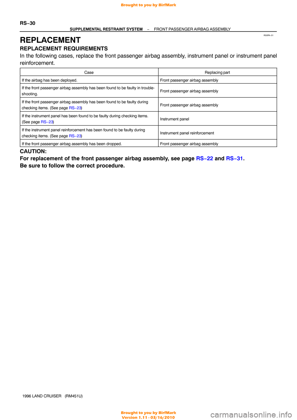
REPLACEMENT
REPLACEMENT REQUIREMENTS
In the following cases, replace the front passenger airbag assembly, instrument panel or instrument panel
reinforcement.
CaseReplacing part
If the airbag has been deployed.Front passenger airbag assembly
If the front passenger airbag assembly has been found to be faulty in tr\
ouble-
shooting.Front passenger airbag assembly
If the front passenger airbag assembly has been found to be faulty durin\
g
checking items. (See page RS−23)Front passenger airbag assembly
If the instrument panel has been found to be faulty during checking item\
s.
(See page RS−23)Instrument panel
If the instrument panel reinforcement has been found to be faulty during\
checking items. (See page RS−23)Instrument panel reinforcement
If the front passenger airbag assembly has been dropped.Front passenger airbag assembly
CAUTION:
For replacement of the front passenger airbag assembly, see page RS−22 and RS−31 .
Be sure to follow the correct procedure.
Brought to you by BirfMark
Brought to you by BirfMark
Version 1.11 - 03/16/2010
Page 1055 of 1399

RS0PC−03
−
SUPPLEMENTAL RESTRAINT SYSTEM FRONT PASSENGER AIRBAG ASSEMBLY
RS−31
1996 LAND CRUISER (RM451U)
INSTALLATION
NOTICE:
Never use airbag parts from another vehicle. When replac-
ing parts, replace with new parts.
1. INSTALL FRONT PASSENGER AIRBAG ASSEMBLY
Install the airbag door and front passenger airbag assembly to
the instrument panel.
CAUTION:
�Make sure that no foreign objects are trapped be-
tween the airbag and the module.
�Do not damage the strap when installing the module.
If the airbag door is cracked or its surface is peeling,
always replace it with a new airbag door.
NOTICE:
If the front passenger airbag assembly has been dropped,
or there are cracks, dents or other defects in the case or
connector, replace the front passenger airbag assembly
with a new one.
2. INSTALL INSTRUMENT PANEL (See page BO−80)
Install the 2 bolts to instrument panel reinforcement. Torque: 20 N·m (210 kgf·cm, 15 ft·lbf)
NOTICE:
Make sure the front passenger airbag assembly is installed
to the specified torque.When installing the instrument pan-
el, take care that the airbag wire harness does not interfere
with other parts and is not pinched between other parts.
3. CONNECT AIRBAG CONNECTOR
(a) Connect the airbag connector.
(b) Install the airbag connector to the airbag bracket.
(c) Install the glove compartment door.
Brought to you by BirfMark
Brought to you by BirfMark
Version 1.11 - 03/16/2010
Page 1192 of 1399

P09286
New O−ring
Grommet Injector
Delivery Pipe WRONG
CORRECT
P09401
Fuel Return Hose
SF−4
−
SFI SFI SYSTEM
632
Author�: Date�:
1996 LAND CRUISER (RM451U)
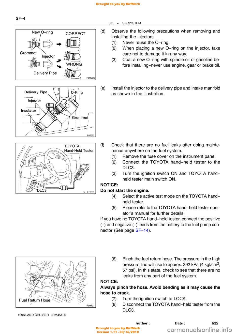
(d) Observe the following precautions when removing and
installing the injectors.
(1) Never reuse the O −ring.
(2) When placing a new O −ring on the injector, take
care not to damage it in any way.
(3) Coat a new O −ring with spindle oil or gasoline be-
fore installing −never use engine, gear or brake oil.
(e) Install the injector to the delivery pipe and intake manifold
as shown in the illustration.
(f) Check that there are no fuel leaks after doing mainte- nance anywhere on the fuel system.
(1) Remove the fuse cover on the instrument panel.
(2) Connect the TOYOTA hand− held tester to the
DLC3.
(3) Turn the ignition switch ON and TOYOTA hand −
held tester main switch ON.
NOTICE:
Do not start the engine. (4) Select the active test mode on the TOYOTA hand−held tester.
(5) Please refer to the TOYOTA hand −held tester oper-
ator ’s manual for further details.
If you have no T OYOTA hand−held tester, connect the positive
(+) and negative ( −) leads from the battery to the fuel pump con-
nector (See page SF−14 ).
(6) Pinch the fuel return hose. The pressure in the high
pressure line will rise to approx. 392 kPa (4 kgf/cm
2,
57 psi). In this state, check to see that there are no
leaks from any part of the fuel system.
NOTICE:
Always pinch the hose. Avoid bending as it may cause the
hose to crack.
(7) Turn the ignition switch to LOCK.
(8) Disconnect the TOYOTA hand −held tester from the
DLC3.
Brought to you by BirfMark
Brought to you by BirfMark
Version 1.11 - 03/16/2010
Page 1193 of 1399
−
SFI SFI SYSTEM
SF−5
633
Author�: Date�:
1996 LAND CRUISER (RM451U)
(g) Install the fuse cover on the instrument panel.
Brought to you by BirfMark
Brought to you by BirfMark
Version 1.11 - 03/16/2010
Page 1216 of 1399

FI4848
FI4849
SF−30
−
SFI INJECTOR
1996 LAND CRUISER (RM451U)
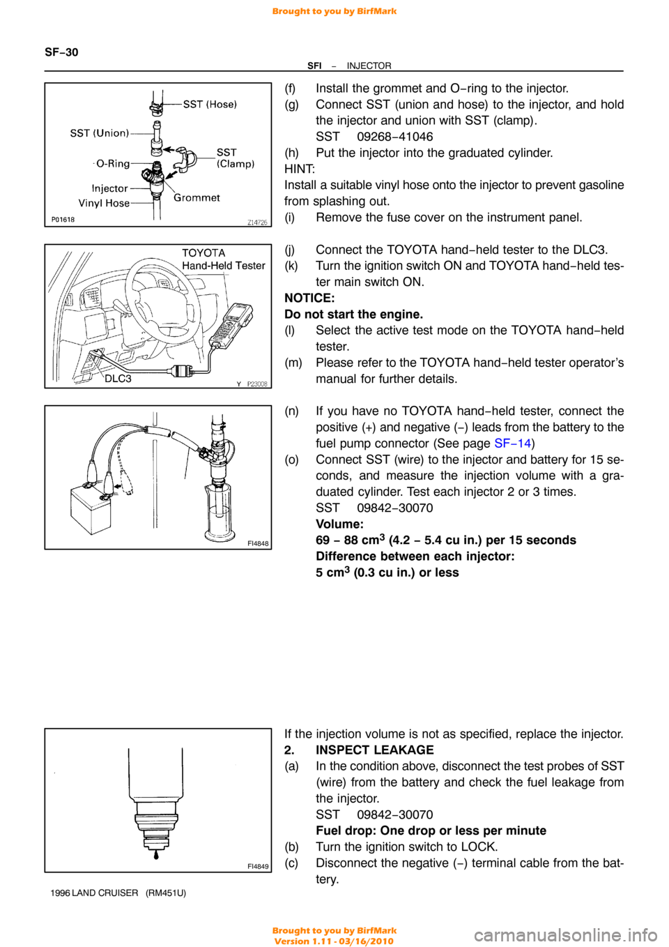
(f) Install the grommet and O−ring to the injector.
(g) Connect SST (union and hose) to the injector, and hold
the injector and union with SST (clamp).
SST 09268−41046
(h) Put the injector into the graduated cylinder.
HINT:
Install a suitable vinyl hose onto the injector to prevent gasoline
from splashing out.
(i) Remove the fuse cover on the instrument panel.
(j) Connect the TOYOTA hand−held tester to the DLC3.
(k) Turn the ignition switch ON and TOYOTA hand−held tes-
ter main switch ON.
NOTICE:
Do not start the engine.
(l) Select the active test mode on the TOYOTA hand −held
tester.
(m) Please refer to the TOYOTA hand −held tester operator’s
manual for further details.
(n) If you have no TOYOTA hand−held tester, connect the positive (+) and negative (−) leads from the battery to the
fuel pump connector (See page SF−14)
(o) Connect SST (wire) to the injector and battery for 15 se- conds, and measure the injection volume with a gra-
duated cylinder. Test each injector 2 or 3 times.
SST 09842−30070
Volume:
69 − 88 cm
3 (4.2 − 5.4 cu in.) per 15 seconds
Difference between each injector:
5 cm
3 (0.3 cu in.) or less
If the injection volume is not as specified, replace the injector.
2. INSPECT LEAKAGE
(a) In the condition above, disconnect the test probes of SST (wire) from the battery and check the fuel leakage from
the injector.
SST 09842−30070
Fuel drop: One drop or less per minute
(b) Turn the ignition switch to LOCK.
(c) Disconnect the negative ( −) terminal cable from the bat-
tery.
Brought to you by BirfMark
Brought to you by BirfMark
Version 1.11 - 03/16/2010
Page 1217 of 1399
−
SFI INJECTOR
SF−31
1996 LAND CRUISER (RM451U)
(d) Remove SST.
SST 09268−41045
(e) Reinstall the fuel pressure regulator to the delivery pipe
(See page SF−22 ).
(f) Disconnect the TOYOTA hand− held tester from the
DLC3.
(g) Reinstall the fuse cover on the instrument panel.
Brought to you by BirfMark
Brought to you by BirfMark
Version 1.11 - 03/16/2010
Page 1253 of 1399
SF0Q2−08
−
SFI FUEL CUT RPM
SF−67
695
Author�: Date�:
1996 LAND CRUISER (RM451U)
FUEL CUT RPM
INSPECTION
1. WARM UP ENGINE
Allow the engine to warm up to normal operating temperature.
2. CONNECT TOYOTA HAND −HELD TESTER OR OBD II
SCAN TOOL
(a) Remove the fuse cover on the instrument panel.
(b) Connect the TOYOTA hand−held tester or OBD II scan tool to the DLC3.
(c) Please refer to the TOYOTA hand−held tester or OBD II
scan tool operator’s manual for further details.
3. INSPECT FUEL CUTOFF PRM
(a) Increase the engine speed to at least 3,500 rpm.
(b) Use a sound scope to check for injector operating noise.
(c) Check that when the throttle lever is released, injector op-
eration noise stops momentarily and then resumes.
HINT:
Measure with the A/C OFF. Fuel return rpm: 1,200 rpm
4. DISCONNECT TOYOTA HAND −HELD TESTER OR
OBD II SCAN TOOL
Brought to you by BirfMark
Brought to you by BirfMark
Version 1.11 - 03/16/2010