Page 705 of 2890
G2M0236
4) Depress clutch pedal to assure there is no abnormality
in the clutch system.
B2M0633A
3. Release Bearing and Lever
A: REMOVAL
1. MECHANICAL APPLICATION TYPE
1) Remove release lever return spring�
1(Models without
hill holder only).
2) Remove the two clips�
2from clutch release lever�3
and remove release bearing�6.
CAUTION:
Be careful not to deform clips.
3) Remove release lever seal�
4.
B2M0174A
4) Remove release lever retainer spring from release lever
pivot with a screwdriver by accessing it through clutch
housing release lever hole. Then remove release lever.
5
2-10SERVICE PROCEDURE
2. On-Car Service - 3. Release Bearing and Lever
Page 707 of 2890

B2M0633A
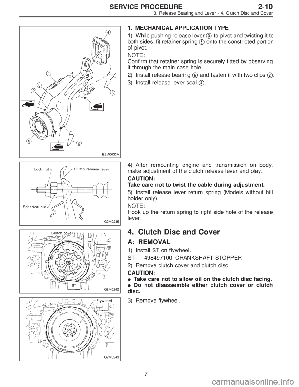
1. MECHANICAL APPLICATION TYPE
1) While pushing release lever�
3to pivot and twisting it to
both sides, fit retainer spring�
5onto the constricted portion
of pivot.
NOTE:
Confirm that retainer spring is securely fitted by observing
it through the main case hole.
2) Install release bearing�
6and fasten it with two clips�2.
3) Install release lever seal�
4.
G2M0235
4) After remounting engine and transmission on body,
make adjustment of the clutch release lever end play.
CAUTION:
Take care not to twist the cable during adjustment.
5) Install release lever return spring (Models without hill
holder only).
NOTE:
Hook up the return spring to right side hole of the release
lever.
G2M0242
4. Clutch Disc and Cover
A: REMOVAL
1) Install ST on flywheel.
ST 498497100 CRANKSHAFT STOPPER
2) Remove clutch cover and clutch disc.
CAUTION:
�Take care not to allow oil on the clutch disc facing.
�Do not disassemble either clutch cover or clutch
disc.
G2M0243
3) Remove flywheel.
7
2-10SERVICE PROCEDURE
3. Release Bearing and Lever - 4. Clutch Disc and Cover
Page 708 of 2890

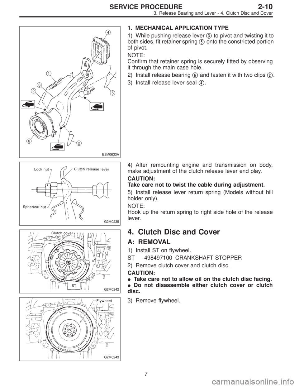
B2M0633A
1. MECHANICAL APPLICATION TYPE
1) While pushing release lever�
3to pivot and twisting it to
both sides, fit retainer spring�
5onto the constricted portion
of pivot.
NOTE:
Confirm that retainer spring is securely fitted by observing
it through the main case hole.
2) Install release bearing�
6and fasten it with two clips�2.
3) Install release lever seal�
4.
G2M0235
4) After remounting engine and transmission on body,
make adjustment of the clutch release lever end play.
CAUTION:
Take care not to twist the cable during adjustment.
5) Install release lever return spring (Models without hill
holder only).
NOTE:
Hook up the return spring to right side hole of the release
lever.
G2M0242
4. Clutch Disc and Cover
A: REMOVAL
1) Install ST on flywheel.
ST 498497100 CRANKSHAFT STOPPER
2) Remove clutch cover and clutch disc.
CAUTION:
�Take care not to allow oil on the clutch disc facing.
�Do not disassemble either clutch cover or clutch
disc.
G2M0243
3) Remove flywheel.
7
2-10SERVICE PROCEDURE
3. Release Bearing and Lever - 4. Clutch Disc and Cover
Page 1208 of 2890
Model 4 Door Sedan Wagon
Engine (cc) 2200 2200
Driving system FWD AWD FWD AWD
L+ L+ LS L+ L+ OUTBACK LS
Hill holder��——��—
Parking
brakeType Mechanical on rear brakes, drum in disc
Effective drum diameter
mm (in)170 (6.69)
Lining dimensions
(length x width x
thickness)
mm (in)162.6 x 30.0 x 3.2 (6.40 x 1.181 x 0.126)
Clearance adjustment Manual adjustment
Master
cylinderType Tandem
Effective diameter
mm (in)26.99 (1-1/16)
Reservoir type Sealed type
Brake fluid reservoir
capacity
cm
3(cu in)190 (11.59)
Brake
boosterType Vacuum suspended
Effective diameter
mm (in)205 + 230 (8.07 + 9.06)
Proportioning
valveSplit point
kPa (kg/cm
2, psi)2,942 (30.0, 427)
Reducing ratio 0.3
Brake line Dual circuit system
ABS—OP STD—OP OP STD
ABS/TCS OP—OP—
�: Equipped on manual transmission vehicle. (Except TCS model)
3
4-4SPECIFICATIONS AND SERVICE DATA
1. Brakes
Page 1210 of 2890
Model Sedan Wagon
Engine (cc) 2200
Driving system FWD AWD FWD AWD
L+ L+ L+ POST BRIGHTON L+ OUTBACK
Hill holder��—— —�—
Parking
brakeType Mechanical on rear brakes, drum in disc
Effective drum diameter
mm (in)228.6 (9)
Lining dimensions
(length x width x
thickness
mm (in)218.8 x 35.0 x 4.1 (8.61 x 1.378 x 0.161)
Clearance adjustment Automatic adjustment
Master
cylinderType Tandem
Effective diameter
mm (in)23.81 (15/16)
Reservoir type Sealed type
Brake fluid reservoir
capacity
cm
3(cu in)190 (11.59)
Brake
boosterType Vacuum suspended
Effective diameter
mm (in)230 (9.06)
Proportioning
valveSplit point
kPa (kg/cm
2, psi)3,678 (37.5, 533)
Reducing ratio 0.3
Brake line Dual circuit system
�: Equipped on manual transmission vehicle.
5
4-4SPECIFICATIONS AND SERVICE DATA
1. Brakes
Page 1212 of 2890
Model Sedan Wagon
Engine (cc) 2500 2200 2500
Driving system AWD
GT LSi GT LSi OUTBACK* OUTBACK*
Hill holder————STD—
Parking
brakeType Mechanical on rear brakes, drum in disc
Effective drum diameter
mm (in)170 (6.69)
Lining dimensions
(length x width x
thickness)
mm (in)162.6 x 30.0 x 3.2 (6.40 x 1.181 x 0.126)
Clearance adjustment Manual adjustment
Master
cylinderType Tandem
Effective diameter
mm (in)26.99 (1-1/16)
Reservoir type Sealed type
Brake fluid reservoir
capacity
cm
3(cu in)190 (11.59)
Brake
boosterType Vacuum suspended
Effective diameter
mm (in)205 + 230 (8.07 + 9.06)
Propor-
tioning
valveSplit point
kPa (kg/cm
2, psi)3,678 (37.5, 533)
Reducing ratio 0.3
Brake line Dual circuit system
ABSSTD
*: Step roof model
7
4-4SPECIFICATIONS AND SERVICE DATA
1. Brakes
Page 1225 of 2890
7. Hill Holder
G4M0359
�1PHV cable
�
2Clamp
�
3Bracket A
�
4Pin
�
5Bushing
�
6Release fork�
7Adjusting nut
�
8Snap pin
�
9Clip
�
10PHV (Pressure hold valve)
�
11Bracket
Tightening torque: N⋅m (kg-m, ft-lb)
T1: 3.4±1.0 (0.35±0.10, 2.5±0.7)
T2: 18±5 (1.8±0.5, 13.0±3.6)
T3: 33±4 (3.4±0.4, 24.6±2.9)
20
4-4COMPONENT PARTS
7. Hill Holder
Page 1263 of 2890

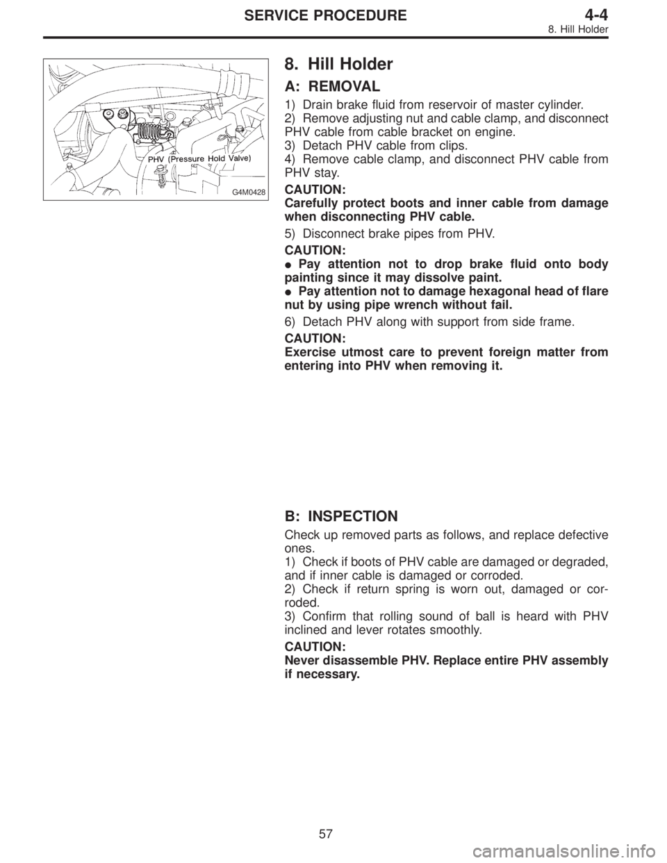
G4M0428
8. Hill Holder
A: REMOVAL
1) Drain brake fluid from reservoir of master cylinder.
2) Remove adjusting nut and cable clamp, and disconnect
PHV cable from cable bracket on engine.
3) Detach PHV cable from clips.
4) Remove cable clamp, and disconnect PHV cable from
PHV stay.
CAUTION:
Carefully protect boots and inner cable from damage
when disconnecting PHV cable.
5) Disconnect brake pipes from PHV.
CAUTION:
�Pay attention not to drop brake fluid onto body
painting since it may dissolve paint.
�Pay attention not to damage hexagonal head of flare
nut by using pipe wrench without fail.
6) Detach PHV along with support from side frame.
CAUTION:
Exercise utmost care to prevent foreign matter from
entering into PHV when removing it.
B: INSPECTION
Check up removed parts as follows, and replace defective
ones.
1) Check if boots of PHV cable are damaged or degraded,
and if inner cable is damaged or corroded.
2) Check if return spring is worn out, damaged or cor-
roded.
3) Confirm that rolling sound of ball is heard with PHV
inclined and lever rotates smoothly.
CAUTION:
Never disassemble PHV. Replace entire PHV assembly
if necessary.
57
4-4SERVICE PROCEDURE
8. Hill Holder