Page 123 of 2189
Valve Clearance
Adjustment
NOTE:
. Valves should be adjusted only when the cylindsrhead temperature is less than 100"F (38"C).
. After adjusting, retorque the crankshaft pulley bolt(see page 6-16).
1, Remove the cylinder head cover.
NOTE; Refer to page e46 when installing the cytinderhead cover.
2. Remove the upper cover (see page 6-19).
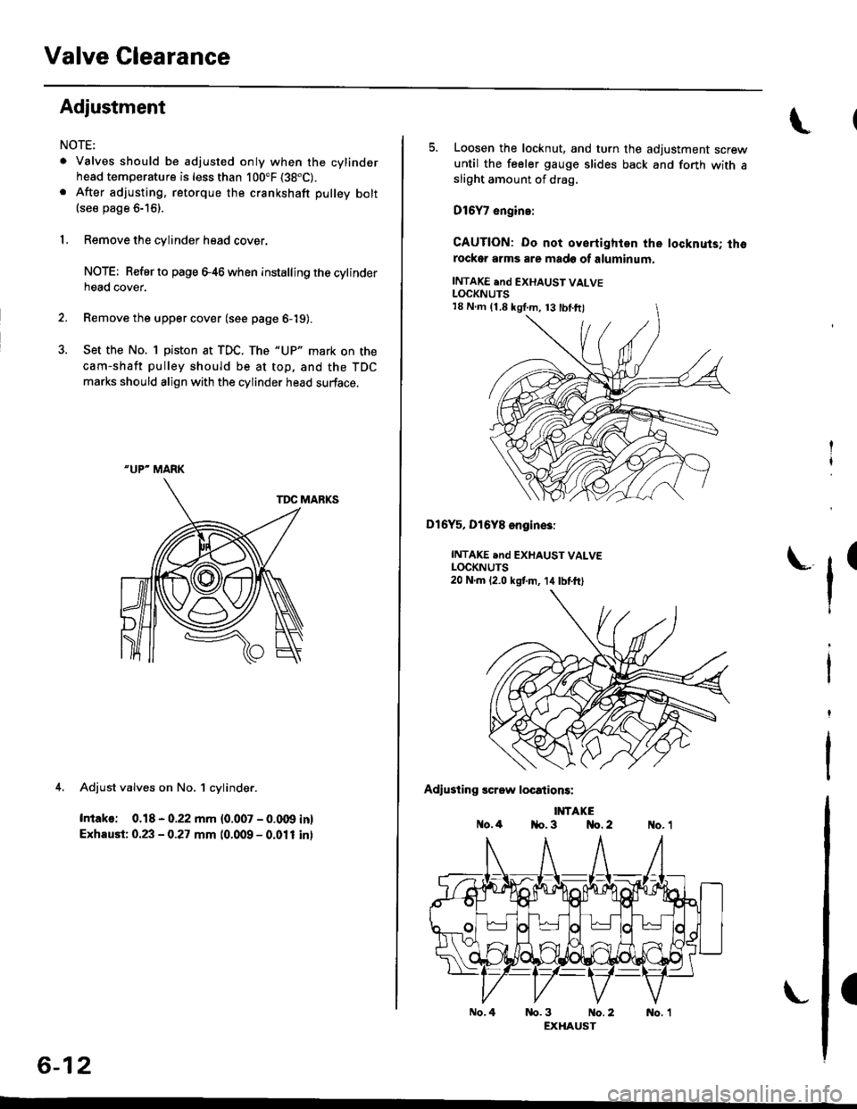
3. Set the No. 1 piston at TDC. The "UP" mark on the
cam-shaft pulley should be at top, and the TDC
marks should align with the cylinder head surface.
TDC MARKS
4. Adjust valves on No, 1 cylinder.
Intako: 0.18 - 0.22 mm {0.007 - 0.009 in}
Exhaust: 0.23 - 0.27 mm (0.009 - 0.011 inl
"UP" MARK
6-12
No.4
5. Loosen the locknut, and turn the adjustment screwuntil the feeler gauge slides back and forth with asliOht amount of drag,
D16Y7 engin.:
CAUTION: Do not oyertighlen the locknuts; thorockor arms are made of aluminum.
INTAKE end EXHAUST VALVELOCKNUTS
Dl6Y5, Dl6Y8 engin€3:
INTAKE .nd EXHAUST VALVELOCKNUTS20 N.m 12.0 kstm, 14lbtft)
Adiusting screw locations:
IMTAKEo.4 1{o. 3 No. 2
tr'
(
nb.3 No.2 No. 1EXHAUST
18 N.m (1.8 kgI.m, 13 tbl.ftl
Page 127 of 2189
Crankshaft Pulley and Pulley Bolt
Replacement
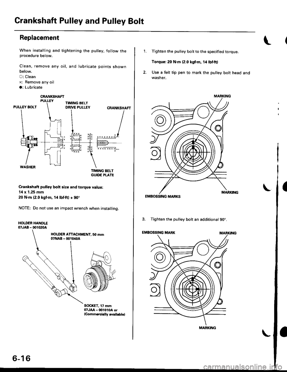
When installing and tightening the pulley. follow theprocedure below,
Clean, remove any oil, and lubricate points shown
below.
O: Clean
x: Bemove any oil
a: Lubricate
TIMING BELTGUIOE PLATE
Crankhaft pulley bolt size and torque value:
14 x 1.25 mm
20 N.m {2.0 kgl.m, 14 lbf.ft) + 90'
NOTE: Do not use an impact wrench when installing.
HOI.I'ER HANDTI07JAB - 001020A
HOLDER ATTACHMENT. 50 mm07NAB - ootoilllA
S(rc(ET, 17 mm07JAA-lxtl010A or{Co.nm.rci.lly .v.il.bl.}
CRANKSHAFT
6-16
'1.Tighten the pulley bolt to the specified torque.
Torque: 20 N.m {2.0 kgf.m, 14 lbf'ft}
Use I felt tip pen to mark the pulley bolt head andwasher.
EMBOSSING MARKS
3. Tighten the pulley bolt an additional 90".
EMBOSSING MABKMARKING
\
MARKING
MARKING
I
Page 129 of 2189

Timing Belt
Inspection
1.
2.
3.
Remove the cylinder head cover.
. Refer to page 6 46 when installing.
Remove the upper cover (see page 6 19).
Inspect the timing belt for cracks and oil or coolantsoakrng.
NOTE:
. Replace the belt if oil or coolant soaKeo.. Remove any oil or solvent that gets on the belt.
Rotate pulleyand inspect belt.
After inspecting, retorque the crankshaft pullev bolt{see page 6- 16).
o- I6
Tension Adjustment
CAUTION: lt*ays aa;j"t the timing bett rension withthe engine cold.
NOTE:
. The tensioner is spring loaded to apply tension to thebelt automatically after making the following adjustment.
. Always rotate the crankshaft counterclockwise whenviewed from the pulley side. Rotating it clockwisemay result in improper adjustment of the belt ten-sion.
. lnspect the timing belt before adjusting the belt ten-ston.
1.Remove the cylinder head cover.
. Refer to page 6,46 when installing.
Remove the upper cover (see page 6,'19).
Rotate the crankshaft five or six revolutions to setthe belt.
Set the No. 'l piston at TDC (see page 6-21).
Loosen the adjusting bolt 180'.
2.
3.
4.
5.
\I
ADJUSTING BOLT44 N.m {4.5 kgt m,33 rbf.ft)
7.
8.
Rotate the crankshaft counterclockwise three teethon the camshaft pulley.
Tighten the adjusting bolt.
After inspecting, retorque the crankshaft pulley bolt(see page 6-16).
Page 167 of 2189
Valve Glearance
Adjustment
NOTE:
. Valves should be adjusted only when the cylinder
head temperaturs is less than 100'F (38'C)'
. After adjusting, retorque the crankshaft pulley bolt to
177 N.m (18.0 kgf'm, 130 lbt'ft)
1. Remove the cylinder head cover'
NOTE: Refer to page G86 when installing the cylin-
der head cover.
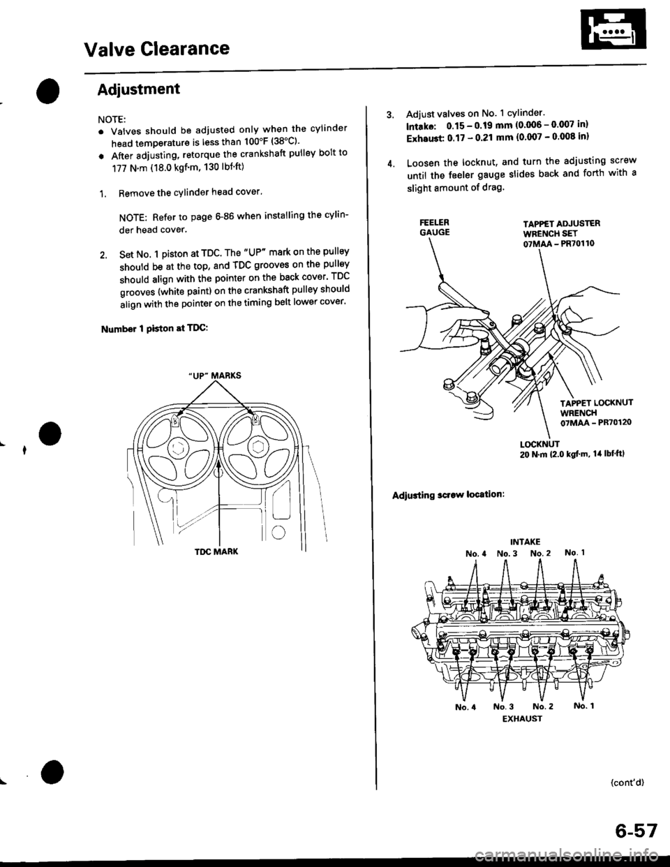
2. Set No. 1 pi$on at TDC. The "UP" mark on the pullsy
should be at the top, and TDC grooves on the pulley
should align with the pointer on the back cover' TDC
grooves {white paint) on the crankshaft pulley should
align with the pointer on the timing belt lower cover'
Number I Piston at TDC:
4.
Adjust valves on No. 1 cylinder.
lntako: 0.15 - 0.19 mm {0'006 - 0.007 in)
ExhaGt 0.17 - 0.21 mm {0'007 - 0 008 inl
Loosen the locknut, and turn the adjusting screw
until the feeler gauge slides back and forth with a
slight amount of drag.
TAPPET ADJUSTERWFENCH SET07MM - PR70110
TAPPET LOCKNUTWRENCH07MAA - PR70120
Adiusting sclaw location:
LOCKNUT20 N.m {2.0 kgf'm, lil lbt'ftl
(cont'd)
6-57
Page 169 of 2189
Crankshaft PulleY and PulleY Bolt
Replacement
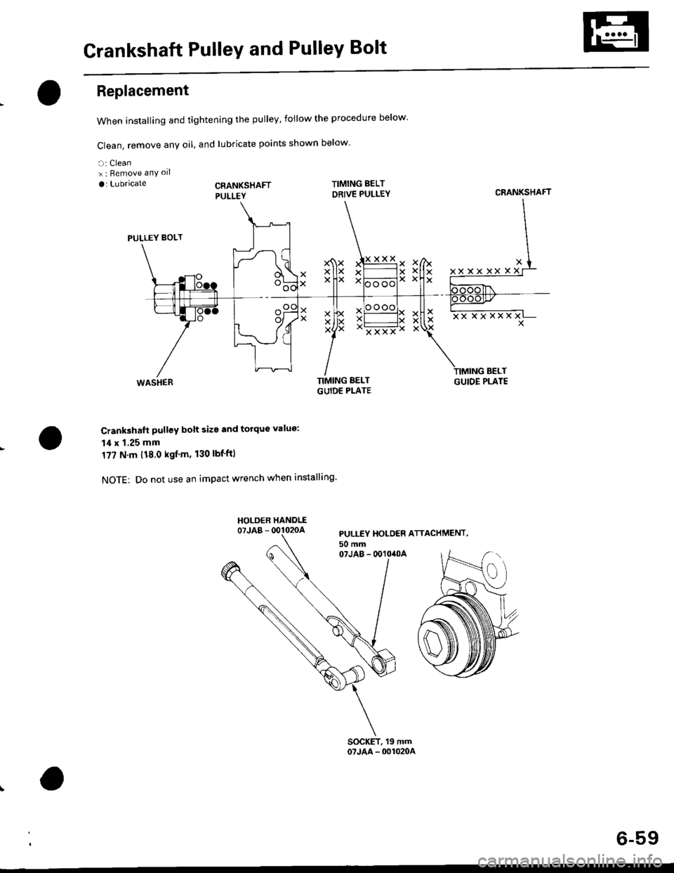
When installing and tightening the pulley, follow the procedure below'
Clean, remove any oil, and lubricate points shown below
a: Cleanx : Bemove anY oll
a: Lubricate
PULLEY BOLT
WASHER TIMIIGUID
Crankshaft pulley bolt size and torque value:
14 x 1.25 mm
177 N.m t18.0 kgtm, 130 lbf'ftl
NOTE: Do not use an impact wrench when installing'
XX
XXxx
Ii
x
XXXXXX
BELTGUIOE PLATE
PULLEY HOLO€R ATTACHMENT,50 mm07JAB - 0O10,OA
CRANKSHAFT
XXXXX
6-59
Page 171 of 2189
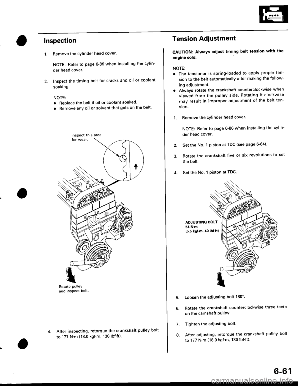
Inspection
Remove the cylinder head cover.
NOTE: Refer to page 6-86 when installing the cylin-
der head cover.
Inspect the timing belt for cracks and oil or coolant
soakrng.
NOTE:
. Replace the belt if oil or coola nt soaked.
. Remove any oil or solvent that gets on the belt'
I
Rotate PUlleYand inspect belt-
After inspecting, retorque the crankshaft pul
to 177 N.m (18.0 kgf'm, 130 lbf'ft)
'L
lnspect thrs area
Tension Adiustment
CAUTION: Always adiust timing belt tension with the
engine cold.
NOTE:
. The tensioner is spring-loaded to apply proper ten
sion to the belt automatically after making the follow-
ing adjustment.
. Always rotate the crankshaft counterclockwise when
viewed from the pulley side. Rotating it clockw'se
may result in improper adjustment of the belt ten-
sion.
1, Remove the cylinder head cover.
NOTE; Refer to page 6-86 when installing the cylin-
der head cover.
2. Set the No. 1 piston at TDC (see page 6-64)
3. Rotate the crankshaft live or six revolutions to set
the belt.
4. Set the No. 1 Piston at TDC
ADJUSTING BOLT
54 N.m(5.5 kgt.m, a0 lbtftl
5.
7.
8.
Loosen the adjusting bolt 180'.
Rotate the crankshaft counterclockwise three teeth
on the camshaft PulleY.
Tighten the adjusting bolt.
After adjusting, retorque the crankshaft pulley bolt
to 177 N.m (18.0 kgf'm, 130 lbnft)
ley bolt
6-61
Page 803 of 2189
19. Remove the engine stiffener and the torque con-
verter cover.
Remove the eight drive plate bolts one at a tlme
while rotating the crankshaft pulley.
Remove the distributor.
Attach a hoisting bracket to the engine, then lift the
engine slightly.
HOISTBRACKET
20.
21.
COVER
23. Place a jack under the transmission. and ra6a :'.
transmission iust enough to take weight otf ol tF.
mounts. then remove the transmission mounl
TRANSMISSIONMOUNT BRACKET
Remove the transmission housing mounting bolts
and the rear engine mounting bolts.
Pull the transmission away from the engine until it
clears the 14 mm dowel pins, then lower it on the
transmission jack.
TRANSMISSION HOUSING
lf necessary, remove the torque converter anc:"
starter motor.
24.
25.
1+16
Page 862 of 2189

Transmission
Installation (cont'dl
9. Attach the torque converter to the drive plate witheight drive plate bolts and torque as follows:Rotate the crankshaft pulley as necessary to tightenthe bolts to 1/2 of the specified torque. then to thefinal torque, in a crisscross pattern.
After tightening the last bolt, check that the crank-shaft rotates freely.
TOROUE: 12 N.m {1.2 kgl.m, 8.7 tbt{r}
10 x 1.25 mm
6x1.0mm12 N.m (1.2 kgt m,8.7 rbt ft)
I 1.25 mm2/t N.m {2.4 kg{.m,17 tbt ftlCONVERTEB
10. Install the torque convener cover and the €nginestiffener.'11. Tighten the crsnkshaft pull€y bolt, if necessary (see
section 61.
12. Connect the ATF cooler hoses to the ATF cooler lines(see page 1,t192).
ATF COOIIRUNE
10 x 1.25 mma,l N.m {4.5 kgl.m,33 rbt.fttRIGHT FRONT 12 x 1.25 mmMOUNT/BRACKET 6.t N.m (6.5 kg{.m,47 tbt ftl
13. Install the right front mounvbracket.
4,r N.m 14.5 kgf.m,33 lbtft)
COVER
L,
14-1A4
SHIFT CABLE
SHIFT CAAE COVER
14. Install the control lever with a new lock washer tothe control shaft, then install the shift cable cover.
CAUION: Taks care not to bend the shift cable.
L(rcK WASHERReplace.
8 x 1,25 r'|m22N-m12.2 tgt m. 16lbnftl
x 1.0 mmtit N.m 11.4 kgt m,10 tbr,ft,
15. lnstall the exhaust pipe A.
NOTE: D16Y8 engine is shown; D16y/ engine is sim_ilar.
Replace.
GASKETReplace.
SELF.LOCKING NUTReplace.10 x 1.25 mm54 N.m (5.5 lgf.m,40 tbt ftl
NUTSELF.LOCKING NUTReplace.8 x 1.25 mm22 N.m {2.2 kgl.m, 16lbtfrl
Replace.8 x 1.25 mm16 N.m {1.6 kgI.m,12 tbf.ft)