1996 HONDA CIVIC pressure control solenoid valve
[x] Cancel search: pressure control solenoid valvePage 888 of 2189
Description
Hydraulic Control {cont'dl
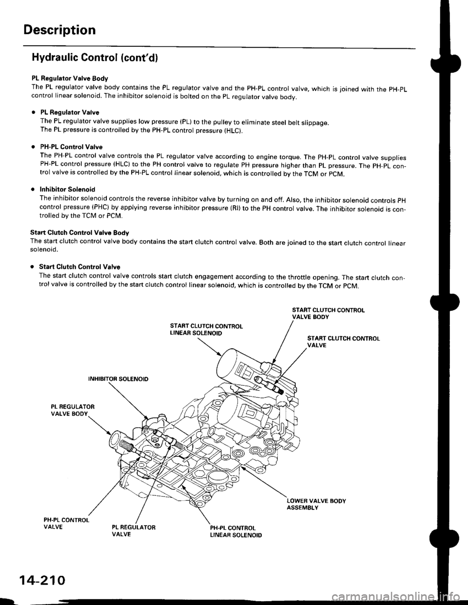
PL Regulator Valve Body
The PL regulator valve body contains the PL regulator valve and the PH-PL control valve. which is joined wirh the pH-pL
control linear solenoid. The inhibitor solenoid is bolted on the pL regulator valve body.
. PL Regulator Valve
The PL regulator valve supplies low p.essure (pL) to the pulley to eliminate steel belt slippage.The PL pressure is controlled by the pH-pL control pressure (HLC).
. PH-PL Control Valve
The PH-PL control valve controls the PL regulator valve according to engine torque. The PH-PL control valve suooliesPH-PL control pressure (HLC) to the PH control valve to regulate PH pressure higher than pL pressure. The pH-pL con-trol valve is controlled by the PH-PL control linear solenoid. which is controlled by the TcM or pcM,
. Inhibitor Solenoid
The inhibitor solenoid controls the reverse inhibitor valve by turning on and off. Also, the inhibitor solenoad controls pH
control pressure (PHC) by applying reverse inhibitor pressure (Rl) to the PH control valve. The inhibitor solenoid is con-trolled by the TCM or Pclvl.
Start Clutch Control Valv€ Body
The start clutch control valve body contains the start clutch control valve. Both are joined to the stan clutch control linearsolenoid.
. Start Clutch Control Valve
The start clutch control valve controls start clutch engagement according to the throttle opening. The start clutch con,trol valve is controlled by the stan clutch control linear solenoid, which is controlled bv the TCM o. pCM.
START CLUTCH CONTROLvAt-vE
LOWER VALVE BODYASSEMBI-Y
PH.PL CONTROLLINEAR SOLENOID
I.
14-210
Page 889 of 2189
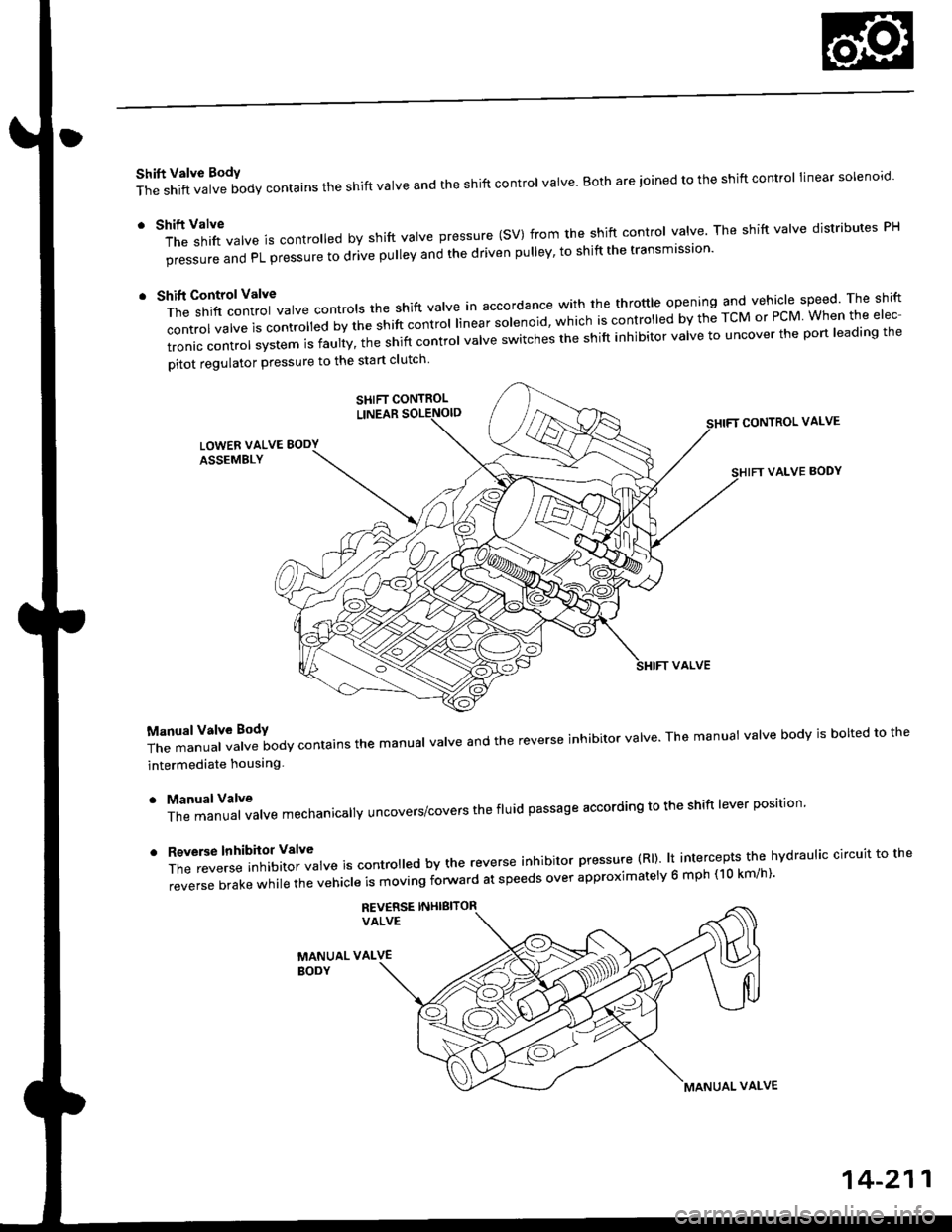
Shift Valve BodY
The shift valve body contains the shift valve and the shift control valve. Both are ioined to the shift control linear solenoro.
r tl'ft1il1rf"","" is controred by shift varve pressure (sV) from the shift contror varve. The shift varve distributes pH
pi""aur" "nO PL pressure to drive pulley and the driven pulley' to shift the transmission'
t t*"rilf:::lr';ivarve contrors the shift varve in accordance with the throttre opening and vehicle speed rhe shift
control valve is convorr"o uv ti" "iirt "ontrol linear solenoid, which is controlled by the TcM or PcM When the elec-
tronic control system is faulty, t;; snift controt uutue "witches the shift inhibitor valve to uncover the port leading the
pitot regulator pressure to the start clutch
CONTROL VALVE
VALVE BODY
T;J:"i"""1ff"t""ilody contains the manuar varve and the reverse inhibitor varve. The manuat varve bodv is borted to the
intermediate houslng
. ManualValve
The manual valve mechanicallY uncovers/covers the fluid passage according to the shift lever position'
'
ff:e;;;.'::'?Xftl::T",* is contro ed by the reverse inhibitor pressure (Rl). lt intercepts the hvdraulic circuit to the
reverse brake while the vehicle is moving forward at speeds over approximatelv 6 mph (10 km/h)'
REV€RSE INHIBITORVALVE
MANUAL VALVEBODY
SHIFT CONTROL
MANUAL VALVE
14-211
Page 893 of 2189

E position, at middle sPeed range
Asthespeedofthevehic|ereachestheprescribedVa|ue,theshiftcontro||inearsolenoidisactivatedbytheTcMorPcM'
Theshiftcontro||inearso|enorocontroIsttresniftcontroIVa|vetoactivateshiftVa|vepressure(SV)'c|utchreducingpres-
sure (CR) trom the clutch reduclng valve becomes shift valve pressure (SV) at the shift control valve Shift valve pressure
(SV)flowstothe|eft"noottr'"st'ittu"tue.theshiftVa|Vetotherightsideandpositioningitinthemidd|eofitstrave|.The
shift valve covers th" pon ao ",oo nLior".irr" tiHl a ,tr" pulleys, and uncovers the port leading low pressure (PL) to the
pu eys. The drive pu ey and tne oriJen priLy |."""iu" to* pressure (PL). At this time, the pulley ratio is in the middle'
Pressure remains to apply the forward clutch and the start clutch'
NOTE: When used, "|eft" or "right" indicates direction on the hydraulic circuit'
(cont'd)
14-215
Page 898 of 2189

Description
Hydraulic Flow (cont'd)
lll position, when th€ electronic control system is fauhy.
when the electronic control svstem (linear solenoids and sensors) is faulty, the transmission uses the pitot pipe pressure(PP) to 311o- rh" u"hicle to drive.
when all linear solenoids and sensors are off because of a faulty electronrc control system, clutch reducing pressure (cR)flows to the start clutch control valve, the manual valve, the PH-PL control valve, and the shift control valve. clutch reduc-ing pressure (cR) becomes shift varve pressure (sV) at the shift contror varve, and shift varve pressure {sv) is appried tothe left end of the shift valve and the right end of the shift inhibitor valve. The shift valve moves to the right side. anduncovers the pon that leads high pressure (PH) to the drive pulley and uncovers the po.t tlr"t r""1" ro,,"-pressure (pL) tothe driven pulley At this time, the pulley ratio is high, The shift inhibitor valve moves to the left side, and uncovers theport that leads shift inhibitor pressure (Sll to the pitot lubrication pipe and the pitot regulator valve. tne prtot lubricationpipe discharges fluid inside of the pitot flange, and discharged fluid enters into the pitot pipe and it is applied to the leftend of the pitot regulator valve. The pitot regulator valve moves lo the right side, and uncovers the port that leads pitotregulator pressure (PR) to the shift inhibitor valve. Pitot regulator pressure {pR) becomes start clutch pressure {sc1 at theshift inhibitor valve, and is applied to the stan clutch. The stan clutch rs engaged. The forward clutch pressure (FWD) isapplied to the forward crutch, and the forward crutch is engaged. This alows the vehicre to drive.
NOTE: When used. "|eft" or ,,right', indicates direction on the hydraulic circuit.
14-220
I.
Page 972 of 2189
t.
rl,
fl,
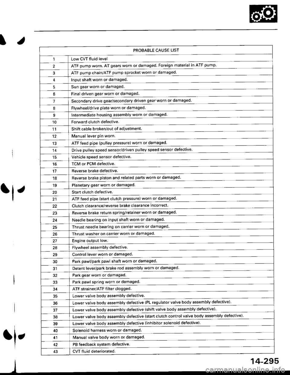
PROBABLE CAUSE LIST
Low CVT fluid level
ATF pump worn. AT gears worn or damaged. Foreign material in ATF pump.
ATF pump chain/ATF pump sprocket worn or damaged.
Input shaft worn or damaged.
Sun gear worn or damaged.
Final driven oear worn or damaqed,
Secondary drive gear/secondary driven gear worn or damaged-
5
6
1
8Flywheel/drive plate worn or damaged.
Intermediate housing assembly worn or damaged.9
'10Forward clutch defective.
Shift cable broken/out of adiustment.
M"nu"t t"uffi
ATF feed pipe (pulley pressure) worn or damaged.
Vchiclc speed sensor defective.
TCM or PCM defective.
Reverse brake detective.
1'�r
't2
13
14
16
'11
'18
1qPlanetary gear worn or damaged.
Sta rt clutch defective.
ATF feed pipe (start clutch pressure) worn or damaged
20
t't
Clutch clearance/reverse brake clearance incorrect.
23Reverse brake return spring/retainer worn or damaged
24Needle bearing on input shaft worn or damaged.
25Thrust needle bearing on carrier worn or damaged.
Thrust washer on carrier worn or damaged.
Enoine outout low.------------------------
Flvwhcel assemblv defective.
Control lever worn or damaged.
Park pawl/park pawl shaft worn or damaged
Detent lever/park brake rod assembly worn or damaged
27
29
30
32Park gear worn or damaged.
Park pawl spring worn or damaged.
ATF strainer/ATF filter clogged.
Lower valve body assembly defective.
Lower valve bodv assemblv defective (PL regulator valve body assembly defective)'
33
34
50
Lower valve bodv assembly defective (shift valve body assembly defective).
Lower valve bodv assemblv defective (start clutch control valve body assembly defective)'
39Lower valve bodv assemblv defective {inhibitor solenoid defective}
40Solenoid harness worn or damaged.
Manual valve body worn or damaged.
PB feedback system defective.
CVT fluid deteriorated.
41
43
14-295
Page 978 of 2189

1.
Start the engine.
Shift to the respective shift lever positions in the table, and measure the following pressures at 1'500 rpm'
. Forward Clutch Pressure
. Reverse Brake Pressure
. Drive Pulley Pressure
. Driven Pulley Pressure
8. Shift to E posltion, and measure the lubrication pressure at 3,000 rpm'
Disconnect the special tool after pressure testlng
Install the sealing boits in the jnspection holes with new sealing washers, and tighten the bolts to the specified
toroue.
TOROUE: 18 N.m {1.8 kgf'm, 13 lbf'ft}
CAUTION: Keep all foreign particles out of the transmission'
9.
10.
PBESSURESHIFT LEVER
POSmONSYMP{OMPROBABLE CAUSE
FLUID PRESSURE
Standard/Ssrvice Limit
Forwa rd
Clutch
ENo or low for-
ward clutch
pressure
Forward Clutch1.4 - 1.75 MPa
(14.3 - 17.8 kgtcm'�, 203 - 253 Psi)
Reverse
Brake
tsNo or low
reverse brake
pressure
Reverse Brake1.4 - 1.75 MPa
(14.3 - '17.8 kg7cm'�, 203 - 253 Psi)
Drive
Pulley
NNo or low
drive pulley
pressure
ATF pump, PH reg-
ulator valve, PL
regulator valve,
Shift valve
0.2 - 0.7 MPa
(2 - 7.1 kgflcm'�, 28 - 101 Psi)
Drive pulley
pressure roo
high
PH regulator valve,
PL regulator valve,
Shift valve. Shift
control linear
solenoid
Driven
Pulley
No or low
driven pulley
pressure
ATF pump, PH reg-
ulator valve, Shift
valve, Shift control
linear solenoid
1.5 - 2.3 MPa
(15.3 - 23.5 kg?cm'�, 218 - 334 Psi)
Driven pulley
pressure too
h igh
PH regulator valve
LubricationNo or low
lubrication
pressure
ATF pump,
Lubrication valve
Above 0.2 MPa
(Above 2 kgf/cm'�. 30 Psi)
14-301
Page 1200 of 2189
t-Operation
t
ABS Control Unit
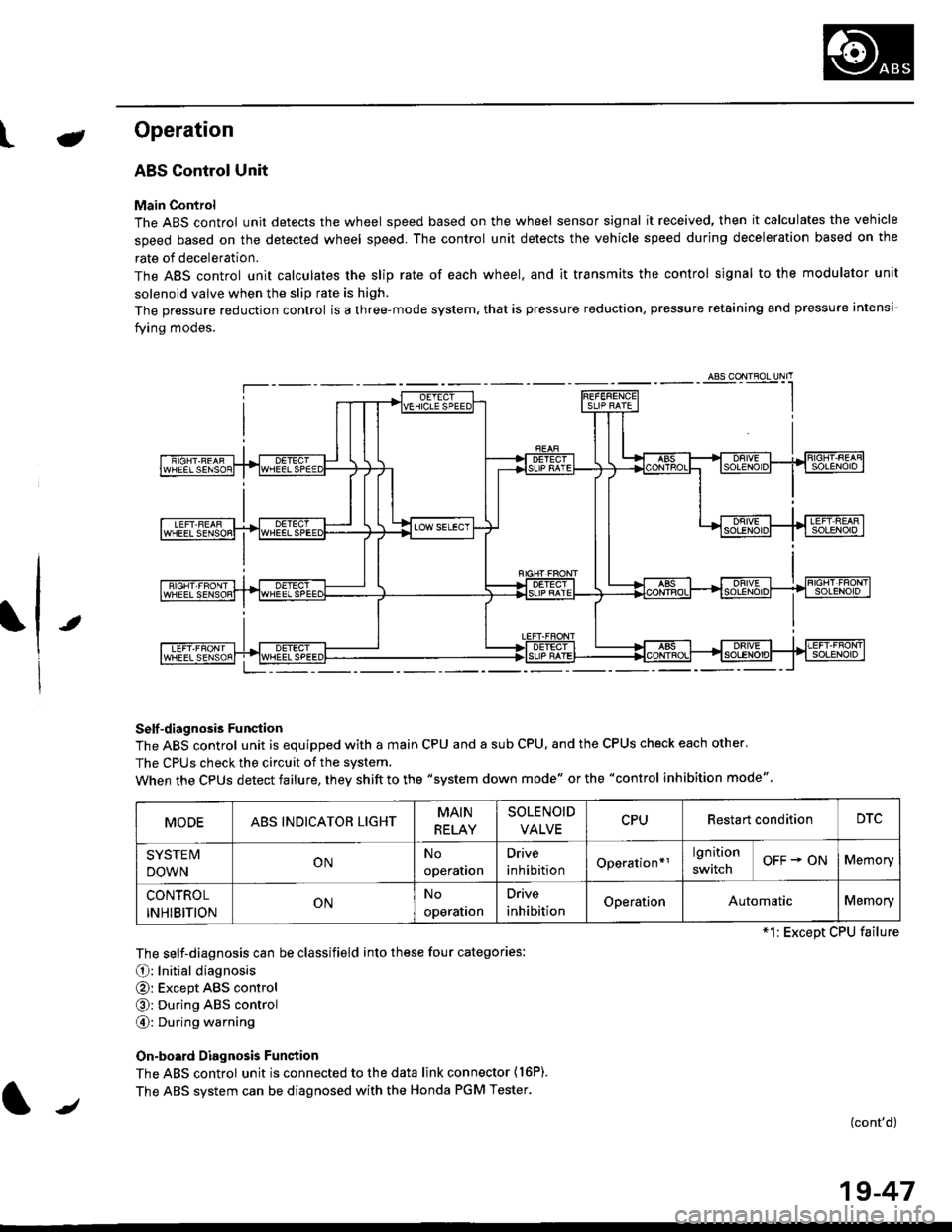
Main Control
The ABS control unit detects the wheel speed based on the wheel sensor signal it received, then it calculates the vehicle
speed based on the detected wheel speed. The control unit detects the vehicle speed during deceleration based on the
rate of deceleration.
The ABS control unit calculates the slip rate of each wheel. and it transmits the control signal to the modulator unit
solenoid valve when the slip rate is high.
The pressure reduction control is a three-mode system, that is pressure reduction, pressure retaining and pressure intensi-
fying modes.
Self -diagnosis Funqtion
The ABS control unit is equipped with a main CPU and a sub CPU, and the CPUS check each other'
The CPUs check the circuit of the svstem.
When the CPUS detect failure, they shift to the "system down mode" or the "control inhibition mode"
The self-diagnosis can be classifield into these four categories:
O: Initial diagnosis
@: Except ABS control
@: During ABS control
@: During warning
On-board Diagnosis Funstion
The ABS control unit is connected to the data link connector {16P).
The ABS system can be diagnosed with the Honda PGM Tester.
(cont'd)
MODEABS INDICATOR LIGHTMAIN
RELAY
SOLENOID
VALVECPURestart conditionDTC
SYSTE IV
DOWNONNo
operation
Drive
inhibitionOperation*rlgnition
switchOFF + ONMemory
CONTROL
INHIBITIONONNo
operalron
Drive
inhibitionOperationAutomaticMemory
*1: Except CPU failure
/
19-47
Page 1201 of 2189
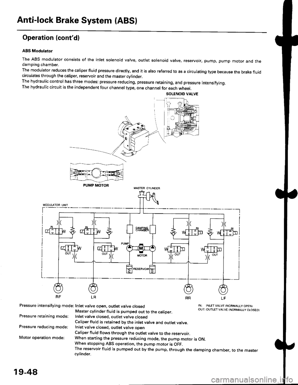
Anti-lock Brake System {ABS)
Operation (cont'dl
ABS Modulator
The ABS modulator consists of the inlet solenoid valve, outlet solenoid valve, reservoir, pump, pump motor and thedamping chamber.
The modulator reduces the caliper fluid pressure directly, and it is also referred to as a circulating type because the brake fluidcirculates through the caliper, reservoir and the master cylinder.The hydraulic control has three modes: pressure reducing, pressure retaining, and pressure intensifying.The hydraulic circuit is the independent four channel type, one channel for each wheel.
RF LR
Pressure intensifying mode: Inlet valve open, outlet valve closed
Pressure retaining mode:
Pressure reducing mode:
Motor operation mode:
rN: INLETVALVE {NORMALtY OpENIOUT: OUTIET VALVE {NORMALIY CTOSED)Master cylinder fluid is pumped out to the caliDer.Inlet valve closed, outlet valve closedCaliper fluid is retained by the inlet valve and outlet valve.Inlet valve closed, outlet valve oDenCaliper fluid flows through the outlet valve to the reservoir.When starting the pressure reducing mode, the pump motor is ON.When stopping ABS operation, the pump motor is OFF.The reservoir fluid is pumped out by the pump, through the damping chamber, to the mastercvlinder.
PUMP MOTOR
19-48