Page 903 of 2189
TCM Circuit Diagram ('96 - 98 Modelsl
UNDEN. HOOD FUSE]RELAY BOX
UNDER OASHFUSE/RELAY 80X
No. 52 1l5A)
No.4l l80A) No.47 (7.5A)
To t 2v lG1sToP sw T HBR( sw- - rur
A/T GEAR POSITIONINDICATOR
IGNITION COIL
Y
I
i
I
IBI-U
rsl
PARKINGBRAKEswrTcH
V
I
I
I
I
IGRN/REO
,t, I
l
I
IGnN,4,vHT
LT GRN
ELKi BI-U
RED
GRN/BLK
NoTEi if :ro 5V
T :To t2v
cRN ---l F----- GnN
Bru -J F------ 61U
8LK
II
Tl
G401G404
,o IJ'^A'
14-226
Page 925 of 2189
Electrical Troubleshooting ('96 - 9g Models)
Troubleshooting Flowchart - lgnition Coil
NOTE: Record all freeze data before you troubleshoot,
Po3rible Cause
. Dbconnected ignition coil con-nectol. Short o. op6n ignition coil wire' F.ulty ignition coil
Wire side ot female terminals
. OBD ll Scan Tool indicates CodePOl25.. Soll-diagnosis E indicarol lightindicates Code 11.
Measure NE Voltrge:1. Disconnect the A {26p) connector from the TCM.2. Start the engine.3. Measure the voltage betweenthe A5 and 413 or A26 termi-nals,
R6p.i. open or short in the wireb€lween the A5 te.minsl and thoignhion coil. It wir€ b OK, checkthe ignition coil test lsoc aoction23t.
ls there battery voltage?
Check for loose TCM connector.It nec$sery. substilute a known-good TCM and .echeck.
Page 1476 of 2189
Troubleshooting
Schematic Symbols
BATTERY
E
@
GROGroLrnd terminal
II_d:
UNDComponent ground
II_..'-
FUSE
--cn-.e
COIL, SOLENOID
r{r
tql'|
CIGARETTE LIGHTER
A
lrl
P
RESISTOR
I
f
VARIAELE RESISTOR
ilH
THERMISTOR
c
IGNITION SWITCH
-fo o.t-
BULB
+
HEATEB
At-l
F
MOTOR
0
PUMP
H
CIRCUIT BREAKER
I
r
Yr
T
HORN
+
DIODE
+
SPEAKER, BUZZER
D
Mast
Y
ANTt:f\,NATRANSISTOR lTrl
II
SWITCH (ln niNormally open
I
/F\t tL I\Y/
I
rrdal positionlNormally closed'*i."n
@
I
LIGHT EMITTINGDIODE ILEDI
A+,
TT
RELAY lln noNormally opon relay
| ....--1'rl*r
til
t "t^f
fmal poaitionlNormally closed relay
ffl-+- |
lrl
lrl
fff
CONDENSER
I
T
CONNTInput
V
I
:CTIONOutput
J
CONNECTOR
*>-
'l!
REED SWITCH
A
tftl
Y
Page 1566 of 2189

Starting System
Starter Test lcont'dl
Ch€ck tor Wear and Damage
The starter should crank the engine smoothly and
steadily, lf the starter engages. but cranks the engine
erratically, remove it, and inspect the starter drive gear
and torque converter or flywheel ring gear for damage.
. Check the drive gear overrunning clutch for binding
or slipping when the armature is rotated with the
drive gear held,- lf damaged. replace the gears.
Check Cranking Voltsge and Curr€nt Draw
Cranking voltage should be no less than 8.5 volts.
Current draw should be no more than 350 amperes.
lf cranking voltage is too low, or current draw too high,
check for;
. dead or low batterv.
. open circuit in starter armature commutator seg-
ments,
. starter armature dragging.
. shorted armature winding.
o excessive drag in engine.
Check Cranking rpm
Engine speed during cranking should be above 100 rpm,
lf speed is too low, check for:
. loose battery or stanerterminals.
. excessively worn starter brushes,
. open circuit in commutator segments.
o dirty or damaged helical spline or drive gear.
. defective drive gear overrunning clutch.
Check Siarter Disengag€ment
With the shift lever in El or @ position (A/T) or with the
clutch pedal depressed (M/T), turn the ignition switch to
START (lll), and release to ON (ll).
The starter drive gear should disengage from the torque
converter or flywheel ring gear when you release the
Key.
lf the drive gear hangs up on the torque converter or fly-
wheel ring gear, check for:
. solenoid plunger and switch malfunction,
. dirty drive gear assembly or damaged overrunning
clutch.
Starter Solenoid Test
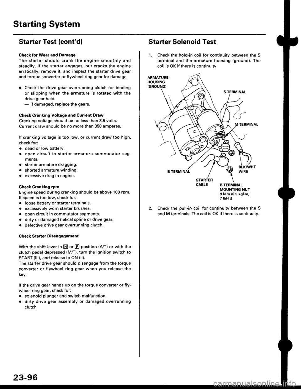
1. Check the hold-in coil for continuitv between the S
terminal and the armature housing (ground). The
coil is OK if there is continuitv,
ARMATUREHOUSING(GROUND)
S TERMINAL
M TERMINAL
B TERMINAL
STARTERCAELE B TERMINALMOUNTING NUTI N.m {0.9 kgf.m,7 tbf.ft)
Check the pull-in coil for continuity between the S
and M terminals. The coil is OK if there is continuity.
Page 1572 of 2189
lgnition System
Component Location Index
IGNITION TIMING CONTROL SYSTEM
. Troubleshooting, section 11
. ldle speed Inspection/Adjustment. section 11
. Inspection and Setting, page 23-105
SERVICE CHECK CONNECTOR {2P}Iwiie colors: 8RN and BLKI
TEST TACI{OMETER CONNECTOB
IGNITION WIRESlnspection and Test, page 23-110
PLUGSInspection, page 23 1 11
Replacement, page 23'106Overhaul, page 23-107lgnition Coil Test, page 23'110lgnition Control Module llCM)Input Test, page 23-109
23-102
Page 1578 of 2189
lgnition System
Distributor Overhaul (cont'dl
TEC:
IGNITION CONTROLMODULE IICM'Input Test, page 23-1
DISTRIBUTOR IGNITION {DI} HOUSINGCheck for cracks and damage.
COVER
DISTRIBUTOR IGNITION IDI) ROTOB
CAP SEALCheck for damage.DISTRIBUTOR IGNITION {DII CAPCheck for cracks, wear,damage, and fouling.Clean or replace,
IGNITION COILTest, page 23-110
O-RINGReplace
\
I
@
TDC/CKP/CYP S€NSORTroubleshooting, section 1 1Do not disassemble.
WHT/BLU
23-104
Page 1579 of 2189

Jlgnition Control Module (lCMl Input Test
NOTE:
. See section 1'l when the malfunction indicator lamp
(MlL) turned on.
. Perform an input test for the ignition control module
(lCM) after finishing the fundamental tests for the
ignition system and the fuel and emissions systems
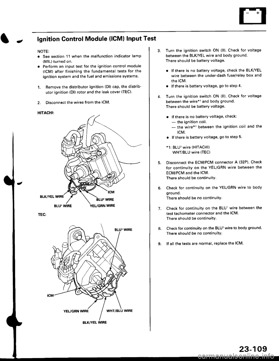
1. Remove the distributor ignition (Dl) cap, the distrib-
utor ignition (Dl) rotor and the leak cover (TEC).
2. Disconnect the wires from the lCM.
HITACHI:
BLK/YEL
TEC:
Turn the ignition switch ON (ll). Check for voltage
between the BLK/YEL wire and body ground.
There should be battery voltage.
. lf there is no battery voltage, check the BLK/YEL
wire between the under-dash fuse/relay box and
rhe lcM.
. lf there is battery voltage, go to step 4.
Turn the ignition switch ON (ll). Check for voltage
between the wire*r and body ground
There should be battery voltage.
. lfthere is no battery voltage, check:
- the ignition coil.
- the wire*1 between the ignition coil and the
tcM.
. lf there is battery voltage, go to step 5
*1: BLU'�wire (HITACHI)
WHT/BLU wire (TEC)
Disconnect the EcM/PCM connector A (32P). Check
for continuity on the YEUGRN wire between the
ECM/PCM and the lCM.
There should be continuity.
Check for continuity on the YEUGRN wire to body
ground.
There should be no continuity.
Check for continuity on the BLUl wire between the
test tachometer connector and the ICM
There should be continuitY.
Check for continuity on the BLUl wire to body ground.
There should be no continuity.
lf all the tests are normal, replace the ICM
7.
23-109
Page 1580 of 2189

lgnition System
lgnition Coil Test
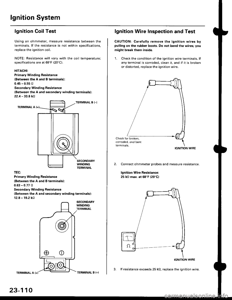
Using an ohmmeter, measure resistance between the
terminals. lf the resistance is not within soecifications.
replace the ignition coil.
NOTE: Resistance will vary with the coil temperature;
specifications are at 68'F (20'C).
HITACHI:
Primary Winding Resistance
{Betwesn the A and B lerminalsl;
0.45 - 0.55 0
Secondary Winding Resistanc€
(Between the A and secondary winding terminals):
22.1 - 33.6 kA
TERMINAL B {-)
TERMINAL A
TEC:
Primary Winding Resistsnce
{Between the A and B terminalsl:
0.63 - 0.77 0
Secondary Winding Resistance
(Between the A and secondary winding terminals):
12.8 - 19.2 kO
SECONDARYWINDINGTERMINAL
TERMINAL A
23-110
TERMINAL B (-)
lgnition Wire lnspection and Test
CAUTION: Carelully remove the ignition wires bypulling on the rubber boots, Do not bend the wires; you
might break them inside.
'1. Check the condition of the ignition wire terminals. lf
any terminal is corroded, clean it, and if it is broken
or distorted, replace the ignition wire.
Check for broken,corroded, and bentlermrnals.IGNITION WIRE
Connect ohmmeter probes and measure resistance.
lgnition Wire Resistance:
25 k0 max. at 68"F (20"C)
IGNITION WIRE
3. lf resistance exceeds 25 kO, replace the ignition wire.