1996 HONDA CIVIC 1 page
[x] Cancel search: 1 pagePage 213 of 2189
Cylinder Block
Inspection
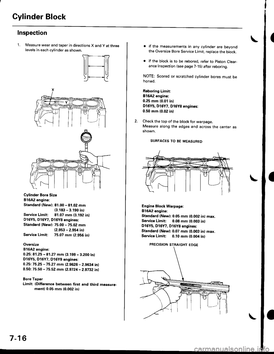
'LMeasure wear and taper in directions X and y at threelevels in each cvlinder as shown.
Cylinder Boro Size
816A2 engine:
Standard (Newl: 81.00 - 81.02 mm
{3.1t|:l - 3.190 intService Limit: 81.07 mm {3.192 in)D16Y5, D16Y7, D16Y8 engines:
Standard lNew): 75.00 - 75.02 mm(2.9s3 - 2.954 in)
Sarvice Limit: 75.07 mm (2.956 in)
Oversize
816A2 engiDe:
0.25t 41.25 - A1.27 mm {3.199 - 3.200 in)D16Y5, D16Y7, D16Y8 Engines:
0.25t 75.25 -15.27 mm (2.9626 - 2.963,0 in)0.50: 75.50 - 75.52 mm 12.9721- 2.9i32 inl
Bore TaDet
Limit: (Difference between first and third measure"ment) 0.05 mm (0.002 inl
7-16
lf the measurements in any cylinder are beyondthe Oversize Bore Service Limit, replace the block.
lf the block is to be rebored. refer to piston Clear-ance Inspection (see page 7-15) after reboring.
NOTE: Scored or scratched cylinder bores must behoned.
Reboring Limit:
Bl642 enginc:
0.25 mm (0.01 in)
Dl6Y5, D16Y7, D16Y8 engin€s:
0.50 mm (0.02 in)
Check the top of the block for warpage,Measure along the edges and across the center asshown.
SURFACES TO BE MEASUREO
Engine Block Warpage:
Bl6A2 engine:
Standard (Now): 0.05 mm {0.002 inl max.Service Limh: 0.08 mm (0.003 in)DtOYs, D16Y7, D16Y8 €nginas:
Standard (N€w): 0.07 mm l0.OO3 inl max.Servica Limit; 0.10 mm {0.00it in)
PRECISION STRAIGHT EDGE
Page 214 of 2189
Cylinder BlockPiston Pins
Bore Honing
1.Measure cylinder bores as shown on page 7-16. lf the
block is to be reused, hone the cylinders and remea-
sure the bores.
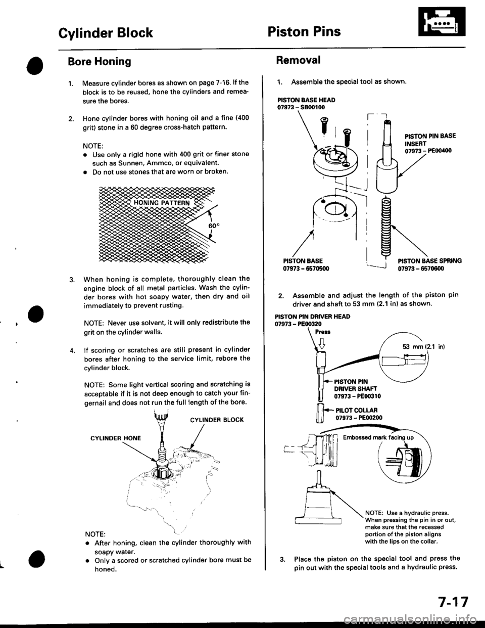
Hone cylinder bores with honing oil 8nd a fine (400
grit) stone in a 60 degree cross-hatch pattern.
NOTE:
. Use only a rigid hone with 400 grit or finer stone
such as Sunnen, Ammco, or equivalent.
. Do not use stones lhat are worn or broken.
When honing is complete, thoroughly clean the
engine block of all metal particles. Wash the cylin-
der bores with hot soapY water, then dry and oil
immediately to prevent rusting.
NOTE: Never use solvent. it will only redistribute the
grit on the cylinder walls.
lf scoring or scratches are still present in cylinder
bores after honing to the service limit, rebore the
cylinder block.
NOTE: Some light vertical scoring and scratching is
acceptable if it is not deep enough to catch your fin-
gernail and does not run the full length of the bore.
CYLINOES BLOCK
CYLINDER
NOTE:
. After honing, clean the cylinder thoroughly with
soapy warer.
. Onlv a scored or scratched cylinder bore must be
noneo.
Removal
l. Assemble the special tool as shown.
PISTON BASE HEAD07973 - SBtx)too
ft
PISTON PIN BASE
INSERT01973 - PE00'0)
ptn
NOTEi Us6 a hydraulic press.When pressing the pin in or out.make sure that the recesssdportion of the piston alignswith the lips on the collar.
rg
g\
lj*N*,""
2. Assemble and adjust the length of the piston
driver and shaft to 53 mm (2.1 inl as shown.
PISTON PIN DRIVER HEAD07973 - PE00320
Proat
0
PISTON PINDRIVER SHAFT0t973 - PEqr310
PILOT COLLAR07973 - PE00200
3. Place the piston on the sp€cial tool and press the
pin out with the special tools and a hydraulic press.
Emboss6d mark facing up
7-17
Page 217 of 2189
Piston Rings
End Gap
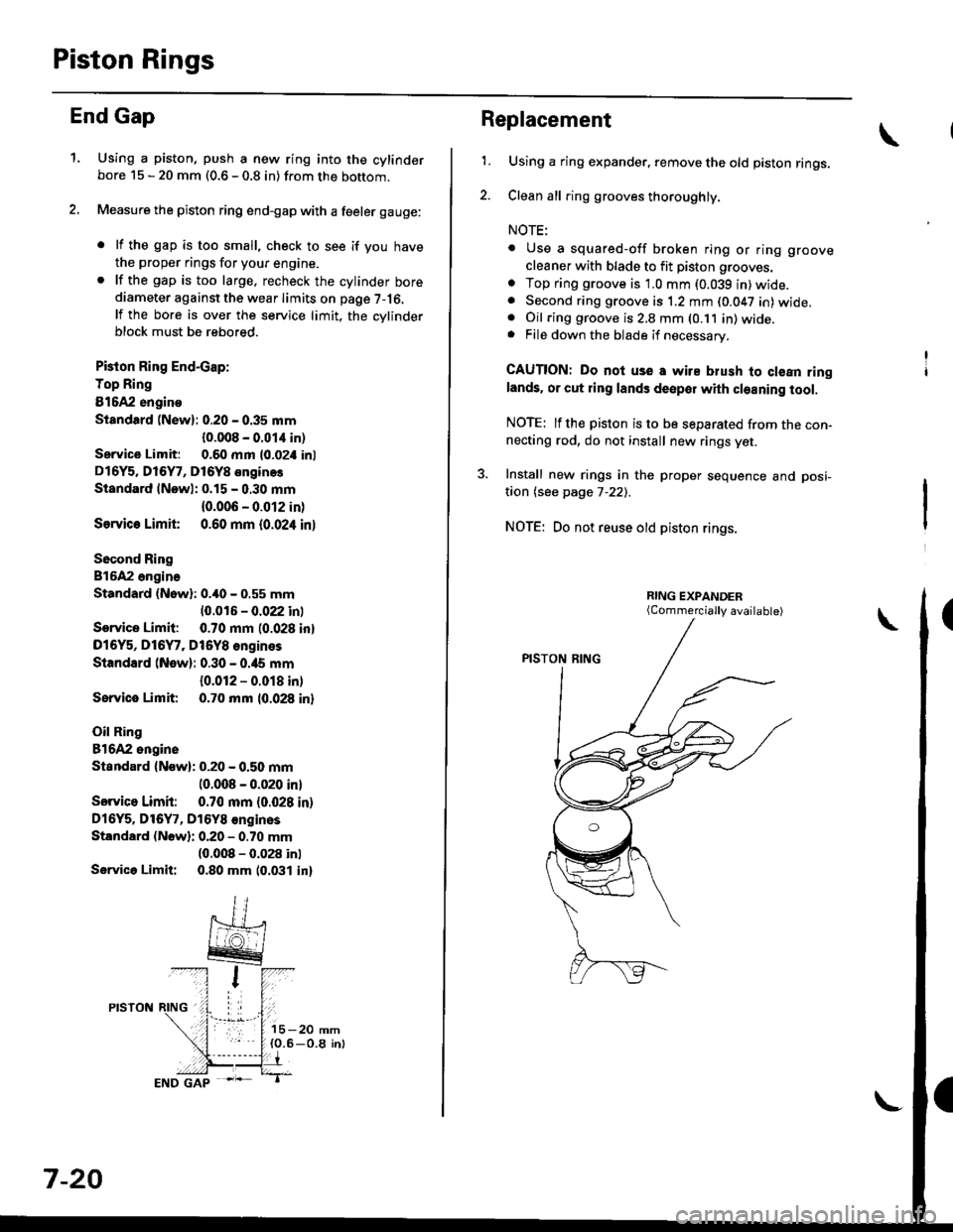
1.Using a piston, push a new ring into the cylinderbore 15 - 20 mm (0.6 - 0.8 in) from the bottom.
Measure the piston ring end-gap with a feeler gauge:
. lf the gap is too small, check to see if you have
the proper rings for your engine.. lf the gap is too large. recheck the cylinder borediameter against the wear limits on page 7-16,
lf the bore is over the service limit, the cvlinderblock must be rebored.
Pkton Ring End-cap:
Top Ring
81642 engino
Siandtrd (New): 0.20 - 0.35 mm
{0.008 - 0.01,1 in)
Service Limit: 0.60 mm l0-02i1 inl
D16Y5. Dl6Y7, D16Y8 enginos
Standard lNewl: 0.15 - 0.30 mm
{0.006 - 0.012 in)
Ssrvic€ Limit 0.60 mm {0.024 inl
Socond Ring
816A2 ongina
Standard (Nowl: 0.40 - 0.55 mm
10.016 - 0.022 inl
Service Limit: 0.70 mm (0.028 inl
D16Y5, D16Y7, Dt6Y8 engines
Standard (New): 0.30 - 0.ia5 mm
{0.012 - 0.018 in)
Sorvice Limit 0.70 mm 10.028 inl
Oil Ring
81642 ongine
Standard {Now): 0.20 - 0.50 mm(0.008 - 0.020 inl
Sorvico Limit: 0.70 mm (0.028 in)
Dl6Y5. Dl6Y7, D16Y8 €nginos
Standard (Nowli 0.20 - 0.70 mm(0.008 - 0.028 inl
Servica Limit: 0.80 mm 10.031 in)
7-20
Replacement
1.Using a ring expander. remove the old piston rings.
Clean all ring grooves thoroughly.
NOTE:
. Use a squared-off broken ring or ring groove
cleaner with blade to fit piston grooves.
o Top ring groove is 1.0 mm (0.039 in)wide.. Second ring groove is 1.2 mm (0.047 in) wide.. Oil ring groove is 2,8 mm (0.11 in) wide.. File down the blade if necessary.
CAUTION: Do noi use a wire blush to clean ringlands. or cut ring lands deepol with cleaning tool.
NOTE: lfthe piston is to be separated from the con-necting rod, do not install new rings yet.
3. Install new rings in the proper sequence and posi-
taon (see page 7-22).
NOTE: Do not reuse old piston rings.
(Commercially available)
Page 219 of 2189

Piston RingsCrankshaft Oil Seal
Alignment (cont'dl
TOP RING ---.>
SECOND RING >
MARK
,a-)
/\_4
o,.r^o( qffi<--sPACER
\Z-.
v
Rotate the rings in their grooves to make sure theydo not bind.
Position the ring end gaps as shown:
DO NOT position any ring gapat piston thrust surfaces.
DO NOT position any ring gapin line with the piston pin hole.OIL RING GAP
SECOND RING GAP
Approx.90
TOP RING GAP
7-22
Installation
The seal surface on the block should be dry.Apply a light coat of oil to the c.ankshaft and tothe lip of the seal.
1. Drive the crankshaft oil seal squarely into the right
side cover using the special tools.
HANDLE DRIVER07749 0010000
seal with thepan number sidefacing out.
Confirm that the clearance is equal all the way
around with a feeler gauge.
Clearance:0.5 - 0.8 mm (0.02 - 0.03 inl
NOTE: Refer to page 8-14 for installation of the oilpumo side crankshaft oil seal.
,(
\
Page 220 of 2189
PistonsGrankshaft
lnstallation
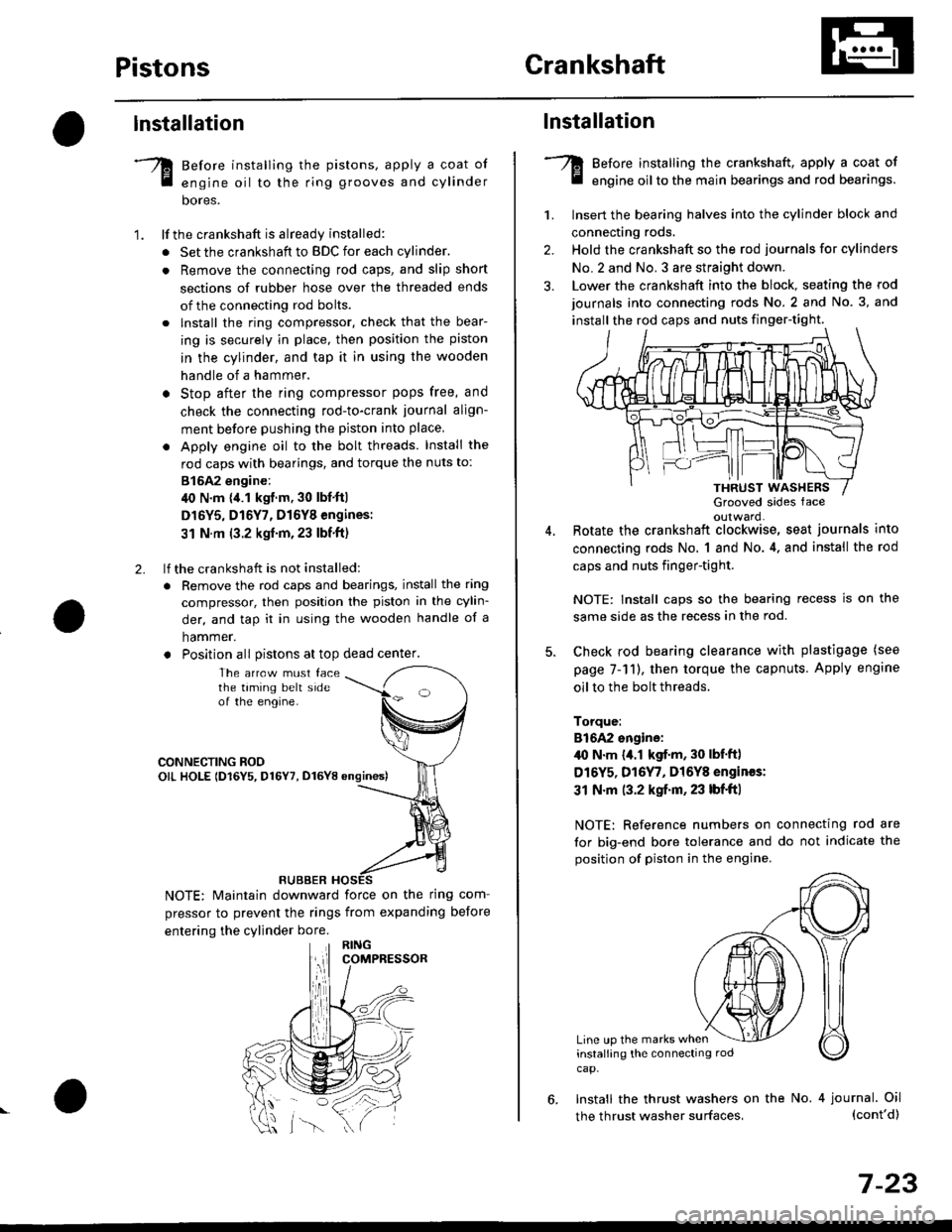
Before installing the pistons, apply a coat of
engine oil to the ring grooves and cylinder
bores.
lf the crankshaft is already installed:
. Set the crankshaft to BDC for each cylinder.
. Remove the connecting rod caps, and slip short
sections of rubber hose over the threaded ends
of the connecting rod bolts.
. lnstall the ring compressor. check that the bear-
ing is securely in place, then position the piston
in the cylinder, and tap it in using the wooden
handle of a hammer.
o Stop after the ring compressor pops free, and
check the connecting rod-to-crank journal align-
ment before pushing the piston into place
. Apply engine oil to the bolt threads. Install the
rod caps with bearings, and torque the nuts to:
815A2 engine:
40 N.m {,1.1 kgf.m, 30 lbf'ft|
D16Y5, D16Y7, D16Y8 engines:
31 N.m (3.2 kgf'm,23 lbf'ft)
lf the crankshaft is not installed:
. Remove the rod caps and bearings, install the ring
compressor, then position the piston in the cylin-
der, and tap it in using the wooden handle of a
hammer.
. Position all Distons at top dead center.
1.
2.
The arrcw must facethe taming belt sideof the engine.
CONNECTING ROOOIL HOLE lD16Y5, D16Y7, D16YB ongines)
NOTE: Maintain downward force on the ring com-
pressor to prevent the rings from expanding before
entering the cylinder bore.
RUBBER
,lll
lnstallation
Before installing the crankshaft, apply a coat of
engine oil to the main bearings and rod bearings.
Insert the bearing halves into the cylinder block and
connecting rods.
Hold the crankshaft so the rod journals for cylinders
No.2 and No. 3 are straight down.
Lower the crankshaft into the block, seating the rod
journals into connecting rods No. 2 and No. 3, and
install the rod caps and nuts finger-tight.
1.
2.
3.
5.
Grooved sides faceoulward.Botate the crankshaft clockwise, seat journals into
connecting rods No, 1 and No.4, and install the rod
caps and nuts finger-tight.
NOTE: Install caps so the bearing recess is on the
same side as the recess in the rod.
Check rod bearing clearance with plastigage (see
page 7-11), then torque the capnuts. Apply engine
oil to the bolt threads.
Torque:
816A2 sngine:/l{, N.m {a.l kgf.m, 30 lbf'ftl
D16Y5, D16Y7, Dl6Y8 engines:
31 N.m (3.2 kgf.m, 23 lbf'ft|
NOTE: Reference numbers on connecting rod are
for big-end bore tolerance and do not indicate the
position of piston in the engine.
Line up the marks wheninstalling the connectrng rod
cap.
6. Install the thrust washers on the No. 4 journal. Oil(cont'd)
7-23
the thrust washer surfaces,
Page 221 of 2189
Crankshaft
Installation (cont'd)
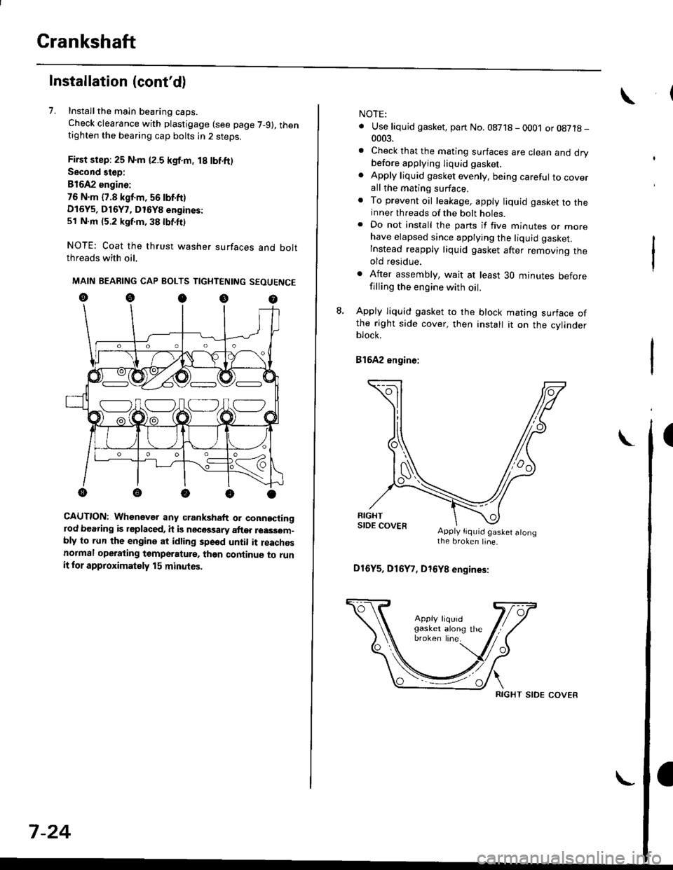
7. Installthe main bearing caps.
Check clearance with plastigage (see page 7-9), thentighten the bearing cap bolts in 2 steps.
First step: 25 N.m {2.5 kgf.m, 18 lbf.ft)
Second stop:
B1642 engine:
76 N.m {7.8 kgf.m, 56 lbf.ft)
D16Y5, D16Y7, D16Y8 engines:
51 N.m (5.2 kgf.m, 38 lbf.ft)
NOTE: Coat the thrust washer surfaces and boltthreads with oil.
MAIN BEARING CAP BOLTS TIGHTENING SEOUENCE
oocoo
CAUTION: Whenever any crankshaft or connectingrod bearing is replaced, it is necGssary after reassom-bly to run the engine at idling spe6d until it reachesnormal operating temperature, than continue to runit for approximately 15 minutos.
:V fr\-/.---\-/.-
7-24
NOTE:
. Use liquid gasket, part No. 08718 - 0001 or08718-0003.
. Check that the mating surfaces are clean and drybefore apptying liquid gasket.
. Apply liquid gasket evenly, being careful to coverall the mating surface.. To prevent oil leakage, apply liquid gasket to theinner threads of the bolt holes.. Do not install the parts if five minutes or morehave elapsed since applying the liquid gasket.
Instead reapply liquid gasket after removing theold residue.
. After assembly, wait at least 30 minutes beforefilling the engine with oil.
L Apply liquid gasket to the block mating surface ofthe right side cover, then install it on the cylinderblock.
Bl6A2 engine;
Apply tiquid gaslet alongthe broken line.
D16Y5, D16Y7, D16Y8 engines:
RIGHT SIDE COVER
Page 226 of 2189

Oil Seals
lnstallation
NOTE:
. Engine removal is not required.
. The crankshaft oil seal housing should be dry.
Apply a light coat of grease to the crankshaft and to
the lips of the seals.
1. Using the special tool, drive in the timing pulley-
end seal until the driver bottoms against the oil
pump.
When the seal is in place, clean any excess grease
off the crankshaft and check that the oil seal lip is
not distorted.
07947 -S800200
lnstall seal with thepart number sadefacing out.
I
2. Measure the flvwheel-end seal thickness and the oil
seal housing depth. Using the special tool. drive the
flywheel-end seal into the rear cover to the point
where the clearance between the bottom of the oil
seal and the right side cover is 0.5 - 0.8 mm (0.02 -
0.03 in) (see page 7-23).
NOTE: Align the hole in the driver attachment with
the Din on the crankshaft.
DRIVER ATTACHMENT0794a-s800101lnslall seal with thepart number sidefacing out.
DRIVER07749-0010000
7 -29
Page 229 of 2189

lllustrated Index
NOTE:
. Use new O-rings when reassembling
. Apply oil to O-rings before installation
. Use liquid gasket, Part No 08718 - 0001 or 08718 -
0003.
CAUTION: Do not overiighten the drain bolt.
6x1.0mm12 N.m (1.2 kqtm,8.7 lbl.ftl. Clean the oil
Ing.
B1642 engine:
pan gasket mating surlaces before install-
WASHERRePlace'
DRAIN BOLT44 N.m (4.5 kgl'm,33 lbt'ft)
Do not overtrghten.
6x1.0mm11 N.m (1.1 kgtm,
OIL PANReler to page 7'27
when installing.
OIL PANGASKETReplace-
6x1.0mm11 N'm (1.1 kgl.m,8 lbf.ft)
OIL BREATHERCHAMEER8
otLSCREEN
GASKETReplace.
€!
fl
[50
BAFFLE PLATE
OIL JET BOLT16 N'm 11.6 kgf.m, 12lbt'ttl
OIL JETInspection, page 8-10
8x1+5mm24 N.d\l2.il kgf.ft,t7 tbtft)
OIL FILTERReplace.
ENGINE OIL PRESSURE SWITCH
Pipe Taper) 28 Threads/inch Clean
Use proper liquid sealant.
6x1.0mm11 N.m 11.1 kgt m,8 tbt.frl
Overhaul. page 8'11Removal/lnspection, Page 8-13
Apply liquid gasket to (cont,d)mating surface of engine block
Replacemenl, page 8-8
Replace.
8-3