1996 HONDA CIVIC 1 page
[x] Cancel search: 1 pagePage 196 of 2189

Cylinder Head
Installation (cont'dl
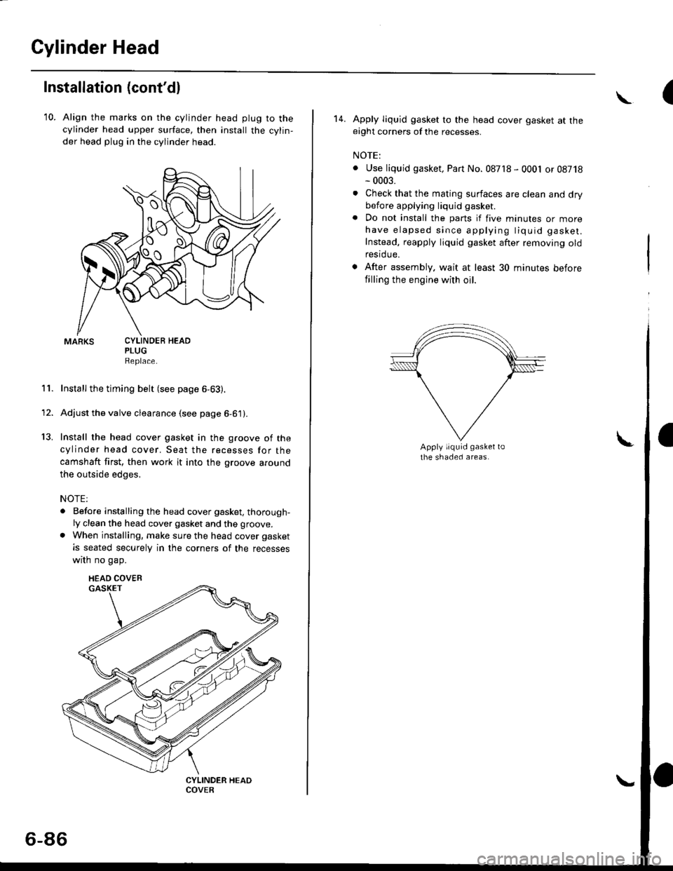
10. Align the marks on the cylinder head plug to thecylinder head upper surface, then install the cylin,
der head plug in the cylinder head.
PLUGReplace.
Install the timing belt (see page 6-63).
Adjust the valve clearance (see page 6-61).
Install the head cover gasket in the groove of the
cylinder head cover. Seat the recesses for the
camshaft first, then work it into the groove around
the outside edges,
NOTE:
. Before installing the head cover gasket, thorough-ly clean the head cover gasket and the groove.
. When installing, make sure the head cover gasket
is seated securely in the corners of the recesses
wrrn no gap.
11.
13.
1'
CYLINDEB HEAD
HEAD COVEB
6-86
(\
14. Apply liquid gasket to the head cover gasket at theeight corners of the recesses.
NOTE:
. Use liquid gasket, Part No. 08718 - 0001 or 08718- 0003.
. Check that the mating surfaces are clean and drybefore applying liquid gasket
. Do not install the parts if five minutes or morehave elapsed since applying tiquid gasket.
Instead, reapply liquid gasket after removing oldrestdue.
. After assembly. wait at least 30 minutes before
filling the engine with oil.
Page 200 of 2189

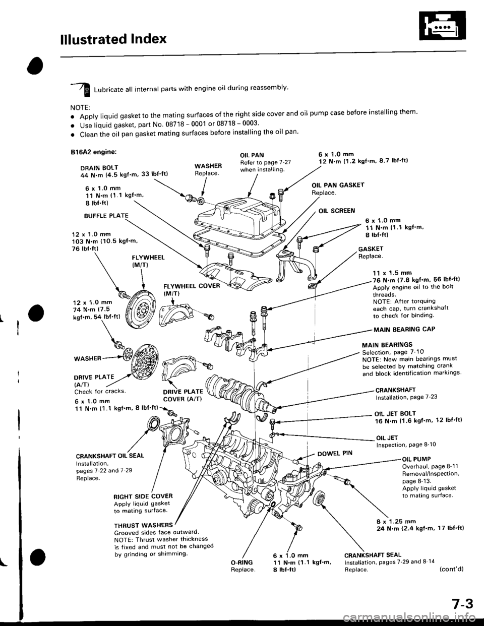
lllustrated Index
I runricate att internal parts with engine oil during reassembly'
NOTE:
o Apply liquid gaskettothe mating surfaces ofthe right side cover and oil pumpcase before installingthem'
. Use liquid gasket, part No 08718-0001 or08718-0003'
. Clean the oil pan gasket mating surfaces betore installing the oil pan
81642 engine:
DRAIN BOLT44 N,m {4.5 kgf'm,33 lbt'ft)
6 x 1.0 mm'11 N.m (1.1 kgI'm,
I tbl.ft)
OIL PANReter to page 7 27when installing.
6 r 1.O mm12 N.m t1.2 kgl'm, 8 7 lbf'lt)
OIL PAN GASKET
BUFFLE PLA
12 x 1.0 mm103 N.m {10.5 kgf'm,
76 tbr.ft)
6 x 1.0 mm11 N.m (1 .1 kgf.m,
8 tbI.fr)
GASKETReplace.FLYWHEEL(M/TI
12 x 1.0 mm
74 N.m (7.5
kof.m, 54 lbf'ft)
1^c{Eb\%^ t*^
*o"rr^--(Wffi
oa*,trto2,.w
FLYWHEEL COVER
IM/T)
DRIVE PLATECOVER (AiT)
11 x 1.5 mm76 N.m (7.9 kgf'm, 56 lbf'ft)
Apply engine oil to the bolt
threads.NOTE: After torqurngeach cap, turn crankshaft
to check for binding.
MAIN EEARING CAP
MAIN BEARINGSSelection, page 7_10
NOTE: New main bearings musl
be selected bY matching crank
and block identification markrngs
CRANKSHAFTInstallation, Page 7'23
OIL JET BOLT16 N.m 11.6 kgf'm, 12 lbl'ft)
OIL JETInspection, Page 8_10
Check for cracks
6x1.0mm11 N.m {1.1 kgf'm, I lbf'ft}
CRANKSHAFT OIL SEAL
Installation,pagesl 22 andl 29
Replace-
DOWEL PINOIL PUMPOverhaul, page 8-'l1Removal/lnspection,page 8-13.Apply liquid gasket
to mating surlace.RIGHT SIDE COVERApply liquid gasket
to mating surface.
THRUST WASHERS8 x 1.25 mm24 N.m {2.4 kgf.m, 17 lbf'ft)Grooved sides face outward
NOTE: Thrusr washer thickness
is tixed and must not be changed
by grinding or shimming
O-RINGReplace
CRANKSHAFT SEAL11 N.m {1.1 kgf'm, lnstallation, pages 7'29 and I 14
a lbt.ltl Heplace. (cont'd)
d#*
Page 201 of 2189

lllustrated Index
(cont'dl
I Luoricate att internal parts with engine oil during reassembly.
NOTE:
' Apply liquid gasket to the mating surfaces ofthe rightside coverand oil pumpcase before installingthem.. Use liquid gasket, part No. 08718 - 0001 or 087,18 _ OOO3.. Clean the oil pan gasket mating surfaces before installing it.
D16Y7 engine:6 x 1.0 mm12 N.m (1.2 kgt.m.8.7 tbf.tr)DRAIN BOLT44 N.m {4.5 kgt.m.33 tbt.ttl
,(
I
I
OIL PAN GASKETFLYWHEEL COVERIM/T)6x 1.0 mm12 N.m ('l .2 kgt.m, 8.7 tbt.trl
OIL PANRefer to page 7-27
Apply liquid gasker tothese points.
Replace.
WASHERReplace.12 x '1.0 mm118 N.m{12.0 kgt.m, 87 tbf.tr}
11 x 1.5 mm51 N.m15.2 kgl.m,38lbtftl
Apply engine oilto the boltthreads.NOTE: After torquingeach cap, turn the crankshaftto check for binding.
MAIN BEARINGSSelection, page 7-10
MAIN BEARING CAP
CRANKSHAFTInstallation, page 7 23
NOTE: New main bearings mustbe selected by matching crankand block identification markings.
6 r 1.0 mm11 N.m {1.1
6 x 1.0 mm11 N.m 11.1
ksI.m, 8 lbt.ft)
OIL SCREEN
kgt.m, 8 lbf.trl
Check for cracks.
CRANKSHAFT OIL SEALInstallation,pages 1 22 a^d 7-29
\:eprace'
GASKETReplace.
6 x 1.O mm11 N.m {1.1 kgt.m,8 rbt.frl
RIGHT SIDE COVERApply liquid gasker1o matrng surface,
OIL PUMPOverhaul, page 8-12Bemoval/lnspection,page 8-13
DOWEL PIN
WASHERSGrooved sides face outward.NOTE: Thrust washer thicknessis fixed and must not be changedby grinding or shimming.
CRANKSHAFT SEAL
l.j"Ji:l"^ pages z.2e --.S)
Replace.
6 x 1.0 mm11 N.m {1.18 tbt.fr)
7-4
BREATHING PORT COVERMOUNT BOLTS6 x 1.0 mm11 N.m {1.1 kgt.m, 8 tbf.fr}Apply liquid gasker tothe boh threads.
DOWEL PIN
Page 202 of 2189

D16Y5, D16Y8 engines:
DRAIN BOLT39 N.m 14.0 kgt'm,
Apply liquid gasket to
these points.
OIL PANRefer to page 7-25
when installing.WASHERReplace.
29 lbl.tt)
\
\^
6 x 1.0 mm q%
P
I
FLYWHEEL COVER(M/T}
12 x 1.0 mm118 N.m(12.0 kgt.m, 87 lbt'ft)
FLYWHEEL (M/TI
t2 N.m 11.2 kgf'm,
8.7 lbl.ftl
11 x 1.5 mm
51 N.m(5.2 kgf'm, 38 lbf ftl
Apply engine oiltothe bolt
threads.NOTE: Aftertorquingeach cap, turn crankshaft
to check for binding.
MAINBEARING
MAIN BEARINGSSelection, page 7-10NOTE: New main bearings must
be selected by matching crank
"nJ lr."i io"irriti"",ion-markings. --------*-i6{\
CRANKSHAFTInstallation, page 7-23
6 r 1.0 mm11 N.m (1 1 kgf'm, I lbf'ttl
OII PAN GASKETReplace.
DRIVE PLATE COVER
{A/T or CVT)
12 r 1.0 mm
74 N.m
17.5 kgl.m, 54 lbf'ft)
DBIVE PLATE {A/T or CVTI
Check for cracks
6 x 1.O mm11 N.m {1.1 kgl'm,
8 tbl.ftl
CRANKSHAFT OIL SEAL
lnstallation,pages 7'?1 and '1 '28
Replace.
RIGHT SIDE COVER
Apply liquid gasket
to mating surface.
OIL SCREEN
GASKETReplace.
OIL PUMPOverhaul, page 8_12Removal/lnspection,page 8-13Apply liquid gasket
to mating surface.
DOWEL PIN
WASHEFS
Grooved sides tace outward
NOTE: Thrust washer thickness
is fixed and must not be changed
bV grinding or shimming.
CRANKSHAFT SEALInstallation, pages 7 29
and 8-14Replace.
BREATHING PORT COVER
MOUNT BOLTS6 x 1.O mm11 f{..n (1.1 kgf'm, 8 lbf'fl)
Apply liquid gasket to
the bolt threads.
O.RINGReplace.
6 x 1.0 mm
11 N.m (1 1 kgl'm,
8 tbr.ftl
(cont'd)
7-5
\
OOWEL PIN
Page 203 of 2189

lllustrated Index
(cont'd)
NOTE: New rod bearings must be selected by matching connecting rod assembly and crankshaft(see page 7,11).identification markings
Lubricate all internal parts with engine oil duringreassembtv.
PISTON INSTALLATION DIRECTION:
EXHAUST
4\/=\6\z\
\e/!rqrf/
INTAKE
PISTON RINGSReplacement. page 7-20Measurement, pages 7 20 andj-21Alignment, page 7-21
PISTON PINRemoval, page 7,17Installation, page 7-18Inspection, page 7,19
CONNECTING RODEnd play, page 7-8Selection, page 7,18
CONNECTING RODBEARINGSClearance, page 7 11Selection, page 7-11
CONNECTING ROD BEARING CAPInstallation, page 7-23NOTE: lnstall caps so thebearing recess is on thesame side as the recessin the rod.
PISTONInspectron, page 7-15NOTE: Betore removing the piston, inspect thetop of the cylinder bore for carbon build-up orridge. Bemove ridge if necessary, page 7-13
ENGINE BLOCKCylinder bore inspection, page 7-16Warpage inspection, page 7,'16Cylinder bore honing, page 7,17
Inspect top of each cylinder borefor carbon build-up or ridgebefore removing piston.Remove ridge if necessary, page 7-13
CONNECTING ROD CAP NUT816A2 €ngin6:9 x 0.75 mm{0 N.m (4.1 kgt m, 30 tbf.ftlD16Y5, Dl6Y7. D16Y8 engines:8 x 0.75 mm3l N.m {3.2 kg{.m,23 tbt.fr)Apply engine oiltothe bolt threads.NOTE: After torquing each bearingcap, rotate crankshaft tocheck for binding.
7-6
Page 205 of 2189

Connecting Rod and Crankshaft
End Play
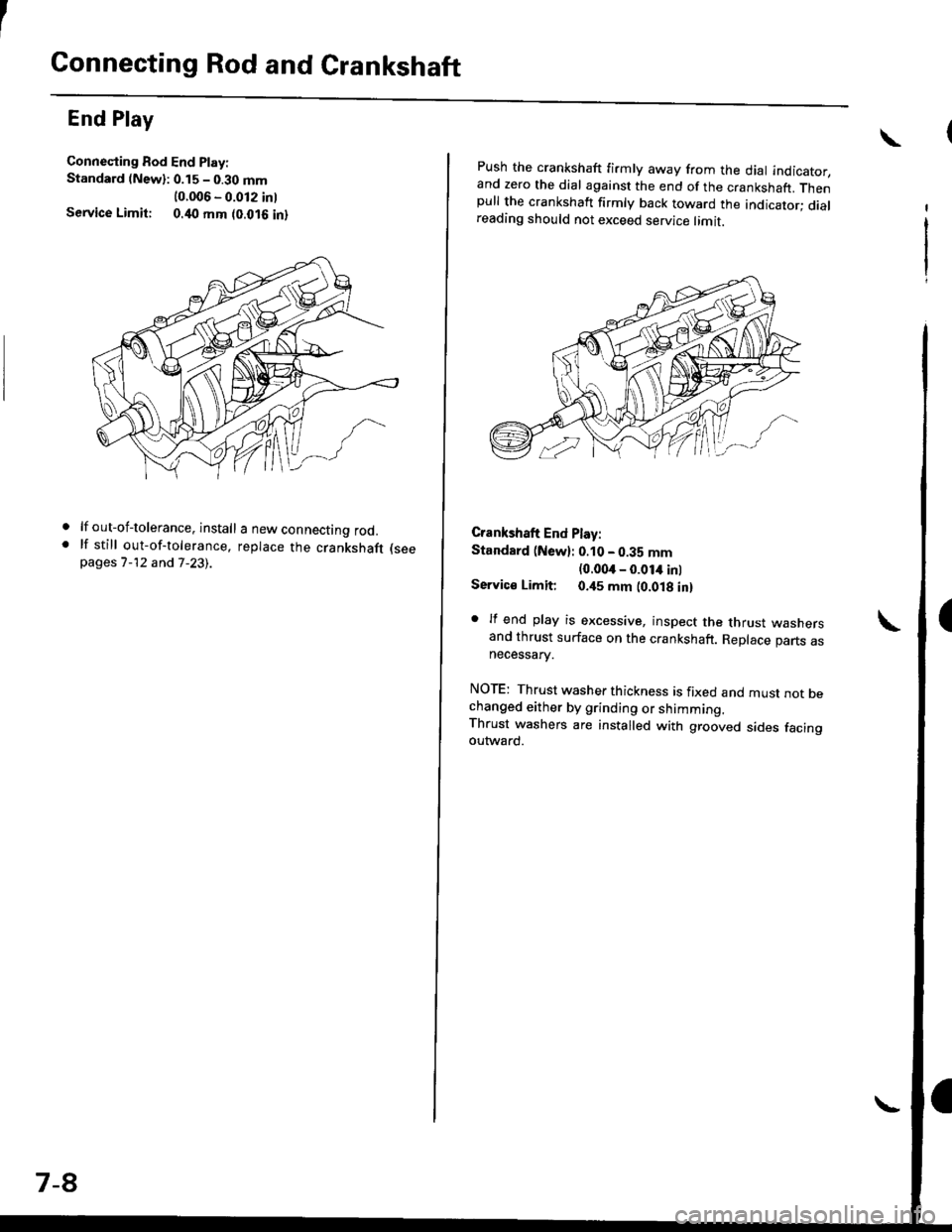
Connecling Bod End Play:
Standard (Newl: 0.15 - 0.30 mm
10.006 - 0.012 inlService Limit: 0.40 mm (0.016 inl
lf out-of-tolerance. install a new connecting rod.lf still out-of-tolerance, replace the crankshaft (seepages 7-12 and 7-23).
a
a
7-8
\
Push the crankshaft firmly away from the dial indicator,and zero the dial against the end of the crankshaft. Thenpull the crankshaft firmly back toward the indicator; dialreading should not exceed service limtr.
Grankshaft End Play:
Standard (Newl: 0.10 - 0.35 mm(0.00,f - 0.01,t inlServic€ Limit 0.it5 mm (0.018 in)
. lf end play is excessive, inspect the thrust washersand thrust surface on the crankshaft. Replace Darts asnecessary.
NOTE: Thrust washer thickness is fixed and must not bechanged either by grinding or shimmrng.Thrust washers are installed with grooved sides facingoutward.
Page 206 of 2189

Main Bearings
4.
Glearance
1.To check main bearing-to-journal oil clearance.
remove the main caps and bearing halves.
Clean each main journal and bearing half with a
clean shop towel.
Place one strip of plastigage across each main jour-
na l.
NOTE: lf the engine is still in the car when you bolt
the main cap down to check clearance, the weight
of the crankshaft and flvwheel will flaften the plasti-
gage further than just the torque on the cap bolt.
and give you an incorrect reading. For an accurate
reading, support the crank with a jack under the
counterweights and check only one bearing at a
time,
Reinstall the bearings and caps, then torque the
bolts.
lst step: 25 N'm (2.5 kgl'm. 18 lbf'ft)
FinalsteD:
B16A2 engine:
76 N.m (7.8 kgf.m, 56 lbf'ft)
D16Y5, Dl6Y7, D16Y8 engines:
51 N.m (5.2 kgf'm, 38 lbf'ft)
NOTE: Do not rotate the crankshaft during inspec-
tron.
Remove the cap and bearing again, and measure the
widest part ot the plastigage.
Main Boaring-toJournal Oil Clearance:
816A2 engine:
Standald {New}:
No. l, 2, 4, 5 Journals:
O.O2,l - 0.042 mm 10'00(B - 0.0017 in)
No. 3 Journals:
0.030 - 0.048 mm {0'0012 - 0'0019 in)
Servico Limit: 0.06 mm {0.002 in,
Dl6Y5, Dl6
r, Dl6Y8 engines:
Standard (Nsw):
No. 1,5 Journals:
0.018 - 0.035 mm {0.0007 - 0'001'[ in)
No. 2. 3, 4 Journals:
0.02,1 - 0.0,(2 mm {0'0009 - 0.0017 in}
Service Limit: 0.05 mm (0.002 in)
\
7-9
7.
lf the plastigage measures too wide or too narrow,
(remove the engine if it's still in the car), remove the
crankshaft, and remove the upper half of the bear-
ing. Install a new. complete bearing with the same
color code {select the color as shown on the next
page), and rechsck the clearance.
CAUTION: Do nol fil€, shim, or scrape the bearings
or tho cap3 to adiust cleatanc€.
lf the plastigage shows the clearance is still incor-
rect, try the next larger or smaller bearing (the color
listed above or below that one), and check again
NOTE: lf the proper clearance cannot be obtained
by using the appropriate larger or smaller bearings,
replace the crankshaft and start over.
Page 212 of 2189

Pistons
Inspection
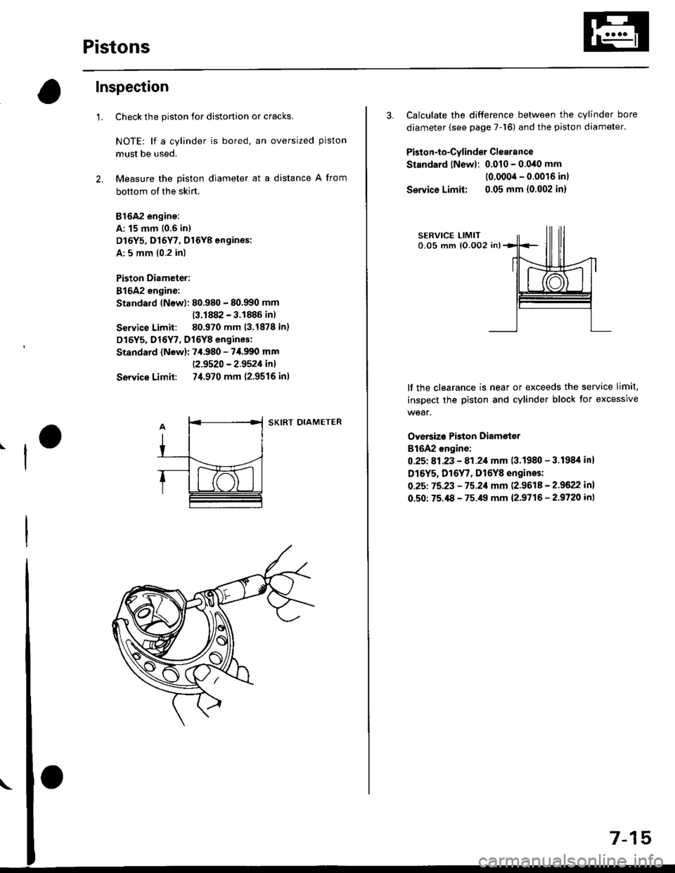
1.Check the piston for distortion or cracks,
NOTE: lf a cylinder is bored. an oversized piston
must be used.
Measure the piston diameter at a distance A from
bottom of the skirt.
816A2 engino:
A: 15 mm 10.6 in)
D16Y5, D16Y7, D16Y8 engines:
A: 5 mm (0.2 inl
Piston Diameter:
816A2 engine:
Standard lNewl: 80.980 - 80.990 mm
13.1882 - 3.1886 in)
Service Limit: 80.970 mm (3.1878 in)
D16Y5, D16Y7, D16Y8 engines:
Standard {New): 7,f.980 - 7i1.990 mm
|.2.9520 - 2.9521in!
Service Limit: 74.970 mm {2.9516 inl
SKIRT DIAMETER
57-1
3. Calculate the difference between the cylinder bore
diameter (see page 7-16) and the piston diameter.
Piston-to-Cylinder Clsarance
Standard lNewl: 0.010 - 0.0,10 mm
(0.0004 - 0.0016 inl
Servico Limit: 0.05 mm {0.002 in}
lf the clearance is near or exceeds the service limit,
inspect the piston and cylinder block for excessive
wear.
Oversizo Piston Diametor
816A2 ongine:
0.25t 81.23 - 81.21 mm (3.1980 - 3.1984 inl
D16Y5. D16Y7, D16Y8 engines:
O.25t 75.23 - 75.21 mm (2.9618 - 2.9622 in)
0.50: 75.i18 - 75.49 mm {2.9716 - 2.9720 in}