Page 1535 of 2189
lr-
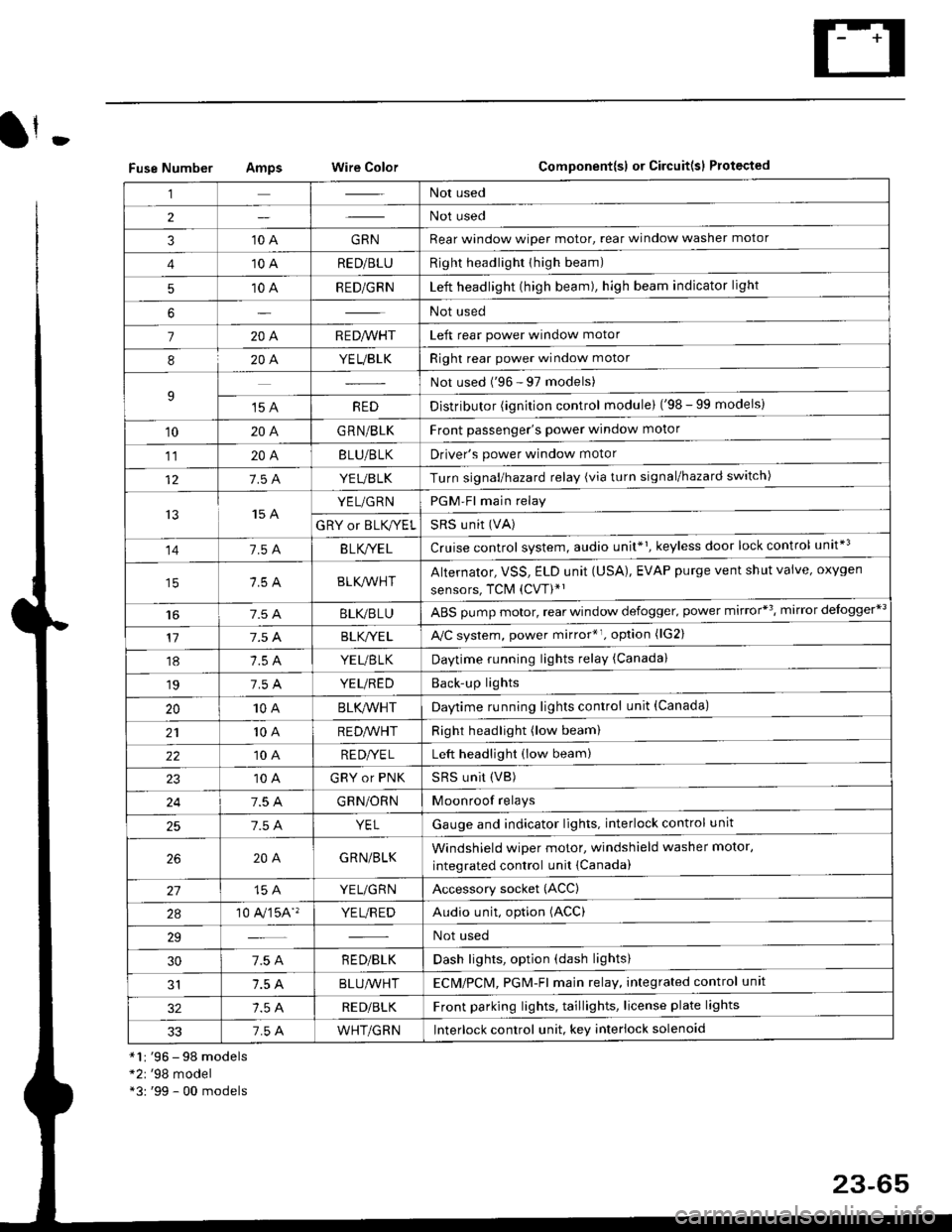
Fuse NumberAmpswire ColorComponent{sl or Circuit(sl Protected
*1r '96 - 98 models*2r '98 model*3: '99 - 00 models
,lNot used
2Not used
310 AGRNRear window wioer motor, rear window washer motor
410 ARED/BLURight headlighr thigh beam)
510 ARED/GRNLeft headlight (high beam), high beam indicator light
6Not used
7204R E D/VVHTLeft rear power window motor
820A.YEUBLKRight rear power window motor
9Not used ('96 - 97 models)
't5 AREDDistributor (ignition control module) ('98 - 99 models)
10204G RN/BLKFront passenger's power window motor
1120ABLU/BLKDriver's power window motor
127.5 AYEUBLKTurn signal/hazard relay (via turn signal/hazard switch)
t515 AYEL/GRNPGM-Fl main relay
GRY or BLK,^/ELSRS u nit (VA)
141.54B LK/YE LCruise control system, audio unit*1, keyless door lock control unit*3
BLK/lr'r'HTAlternator, VSS, ELD unit (USA), EVAP purge vent shut valve, oxygen
sensors, TCM (CVT)*'
t6BLI(,/BLUABS pump motor, rear window defogger. power mirror*3, mirror delogger*3
177.5 ABLK,/YE LA,/C system, power mirror*r. option (lG2)
18YEUBTKDaytime running lights relay (Canada)
197.5 AYEUREDBack'up lights
2010ABLK/VVHTDaytime running lights control unit (Canada)
2110 AREDA/VHTRight headlight (low beam)
2210 ARE DI/E LLeft headlight (low beam)
10 AGRY or PNKSRS UNit (VB)
247.5 AGRN/ORNMoonroof relays
257.5 AYELGauge and indicator lights. interlock control unit
204GRN/BLKWindshield wiper motor, windshield washer motor,
integrated control unit {Canada)
15 AYEL/GRNAccessory socket (ACC)
2a10 A,/'�]5A''YE L/R EDAudio unit, option (ACC)
29Not used
307.5 AR ED/BLKDash lights, option (dash lights)
1.5 ABLUA/VHTECM/PCl\4, PGM-Fl majn relay, integrated control unit
RED/BLKFront parking lights, taillights, license plate lights
337.5 AWHT/GRNlnterlock control unit. key interlock solenoid
23-65
Page 1539 of 2189
t
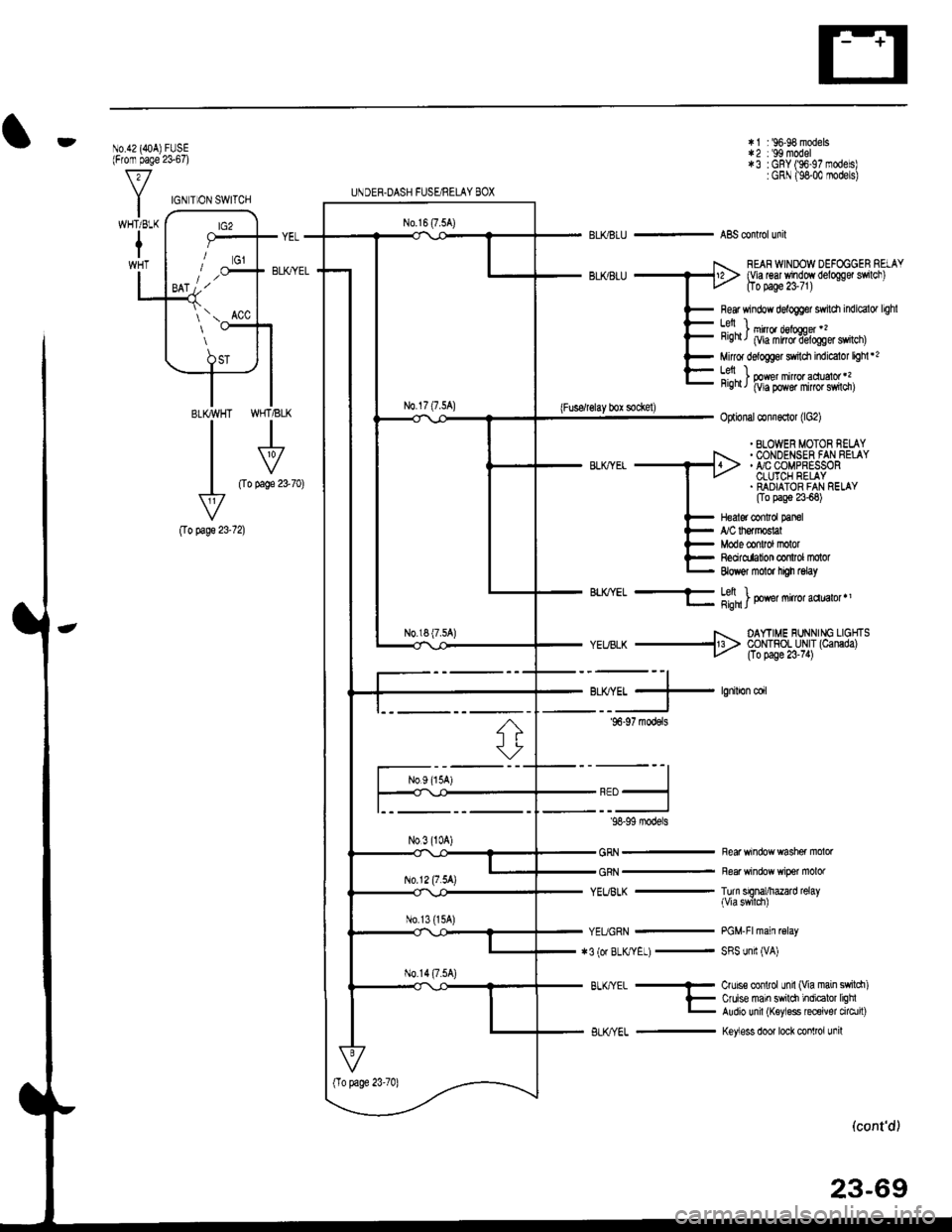
BLI(BLU - ABS controlunit
r 96'9€ models: 99 modol: GRY (96-97 models: GRN (9&00 models
Rear window d8loloer swilch indicalo. l€ht
::: ) mirroa d€loQor r?Hrgn, Ma miror i;logger sYritch)
Miror dolog06r $ tdr indicalor lighl'2
191 ) oo*e, ri,,o, "qraor',hEn, ivra pow mircr sMdr
odional conna.ior 1lG2)
*2*3
REAR WINDOW DEFOGGER RELAY{Via Gar wndow deloggot sw ch)fro page 23-71 )
N0.42 (40A)FUSE(Frofir page 23.67)
WHTi BLK
t
lFusdrelay bor socl(el)WHT/BLK
I
V
fro page 23'70)
Ipag6 23-0o
. BLOWER MOTOR FELAY. CONDETISER FAN RETAY. ,VC COMPRESSORCLWCH RELAY. NAONTOR FAN RELAY0o pag€ 2368)
12)Heal€r conlrol Pan6l,ryC her|lDshlMode conlrol molorReorolalion conlol molorAow€r molor iEh aelay
YEUBLK -
YEUGRN -
:rl l^r A k/YF l -
B./"|YEL - Ctr|s€ conlrcl Jn (Via main swildr)
l- C'uEe ma'4 swildr 'ndicalot lEhlL Audio unil (K€y oss rece'ver drol4)
BLKryEL - Kevless door tock conlroi unit
UNDER.DASH FUSE/RELAY BOX
N0.16 (7.5A)
(To page 23'70)
No.l2 (7.5A)
N0.13 (15A)
N0.14 (7.54)
IGN TION SWITCH
BA1 ;.'
1 '.._ ACC
q, (/vrr - |.fi II ::: I mrcr mircr aqua|ol'r
F DAY'IME FUNNING LIGHISvELrtsLK -113> CONTFOL UN|T (Ceneda)t'- (f o We 23-71)
,F1J- ,n*,"',
'96-97 mod6ls
""j
'98-99 models
GRN -
GRN _
Rear window washer molof
Rear window wiper molor
Turn srgnal/hazard relay(Viaswilch)
PGM-Flmain relay
SRS unii (VA)
(cont'd)
23-69
Page 1550 of 2189
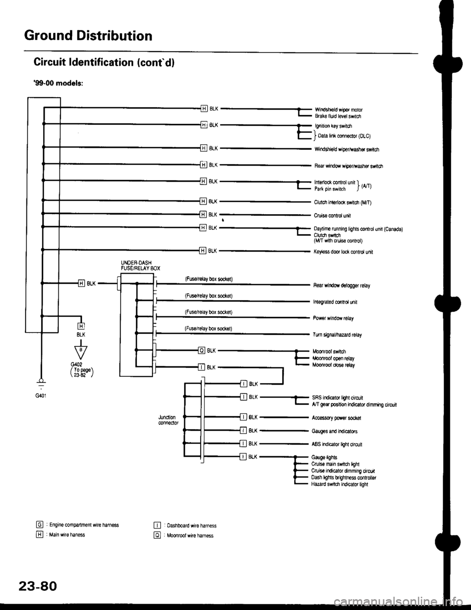
Ground Distribution
Circuit ldentification (conf d)
'99-00 models:
EWir'rdshield wipe. nolorBGke lluid level swildl
6L^ -- €nrnon €y sv loa-)l- i oala hnk conn€clol lDlcl
8LK
BLK
Windshigld dper^vash€r switdt
Re windo wiperlflasher ssitch
BLK
J
To 9aqe23.A2-
tr
E
UNOEN.DASHFUSgRELAYSOX
-r^ -..-- tmenoo( @ rotunn l ._.l- pa* oin swhrh l\4tl
ClLrldr inlerlod swildr (M,T)
Cruis€ confol unit
BL( ---- Oay me running tights controtund (Canadal_ Ctuldt sfich(l,t/T vrith ruis€ cor rol)
Key'ess door lock control unit
(Fuserelay box sockst)
(Fus€/relay box sod(8t)
(Fusdrelay bor sockel)
(Fuserelay box sock€l)
8LK
BLK
BLK
BLK
8LK
near windoYr delogger rclay
htograted co.Ird unil
Tum signal/hazard lelay
SRS indicalor lighl cirqtil,y'T goer position indicator dimming cirdlit
Accessory poxer sod@l
Gaug€s and indicators
ABS indicalor light ciro.lil
Gauge lighbCruis€ main swil$ lEhlCruiso indicator dimming ciroritoash lohls brighlness confolbtHazard s$tdl indicator liohl
G401
(
oh --- Moonroot swnm
t- iroonrool open relay- Moonroot dose reiay
t
fil BLK -J
: Engine @mparlrnenl wire hamess
: Main wire haness
,JUncll0n@nfreclol
E : Dashboard wire harness
El , Mo*tool *ite har"..
23-80
Page 1616 of 2189
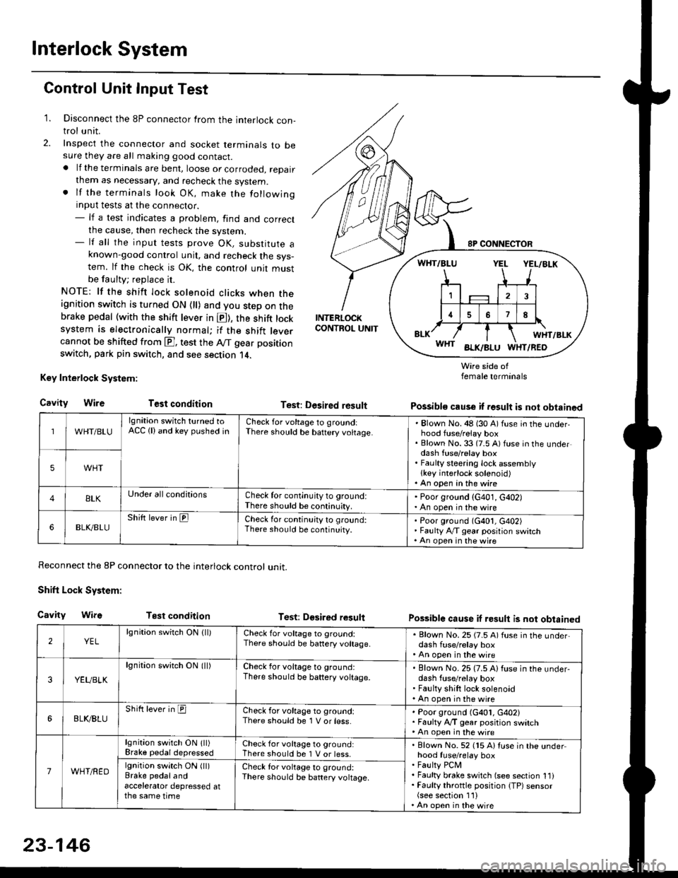
Interlock System
Control Unit Input Test
1. Disconnect the 8P connector from the interlock con-trol unit.
2. Inspect the connector and socket terminals to besure they are all making good contact.. lf the terminals are bent, loose or corroded, repairthem as necessary, and recheck the system.. lf the terminals look OK, make the followinginput tests at the connector.- lf a test indicates a problem, find and correctthe cause, then recheck the system.- lf all the input tests prove OK, substitute aknown-good control unit, and recheck the sys-tem. lf the check is OK, the control unit mustbe faulty; replace it.
NOTE: lf the shift lock solenoid clicks when theignition switch is turned ON {ll) and you step on thebrake pedal (with the shift lever in E), the shift locksystem is electronically normal; if the shift leve.cannot be shifted from E], test the Aff gear position
switch, park pin switch, and see section 14.
Key Interlock System:
CavityWireTest condition
Reconnect the 8P connector to the interlock control unit.
Shift Lock System:
Cavity WifsTest condition
INTERLOCKCONTROL UNIT
Test: Desired result
Test: Dgsired result
Wire side offemale terminals
Possible cause if result is not obtained
Possible cause if result is not obtained
WHT/BLU
lgnition switch turned toACC (lland key pushed inCheck for voltage to groundiThere should be baftery voltage.Blown No. 48 (30 A) fuse in the underhood fuse/relay boxBlown No. 33 (7.5 A) fuse in the underdash fuse/relay boxFaulty steering lock assemblylkey interlock solenoid)An open in the wire
5WHT
BLKUnder all conditionsCheck for continuity to ground:There should be continuity.
' Poor ground (G401, G402). An open in the wire
6BLK./BLUShift lever in ElCheck for continu;ty to ground:There should be continuity.Poor ground (G401, G402)Faulty Ay'T gear position switchAn open in the wire
2YELlgnition switch ON lll)Check for voltage to ground:There should be banery voltage.
. Blown No. 25 (7.5 A) fuse in the under,dash fuse/relay box. An open in the wire
3YEUBLK
lgnition swirch ON (ll)Check for voltage to ground:There should be baftery voltage.Blown No. 25 (7.5 A) fuse in the under-dash fuse/relay boxFaulty shift lock solenoidAn open in the wire
6BLI(BLUShift lever in ICheck for voltage to ground:There should be 1 V or less.Poor ground (G401, G402)Faulty A,/T gear position switchAn open in the wire
7WHT/RED
lgnition switch ON lll)Brake pedaldepressedCheck for voltage to ground:There should be 1 V or less.Blown No. 52 (15 A) Iuse in the underhood fuse/relay boxFaulty PCMFaulty brake switch (see section 1l)Faulty throttle position {TP) sensor(see section 1'l )An open in the wire
lgnition switch ON (ll)Brake pedalandaccelerator depressed atthe same time
Check for voltage to ground:There sho(Jld be battery voltage.
23-146
Page 1624 of 2189
A/T Gear Position Indicator
A/T Gear Position Switch Test
1. Remove the front console (see section 2O).
2. Disconnect the 14P connector from the A/T gear position switch.
3. Check for continuity between the terminals in each switch position according to the table.
' Move the shift lever back and forth without pushing the shift lever at each switch position, and check for continuitywithin the range of free play of the shift lever.' lf there is no continuity within the range of free play, adjust the position of the switch as described on the nextpage.
Terminal side of male terminals
A/T Gear Position Switch
+ 1 : With cruise controlsystem
23-154
Eack - upLight SwitchNeutralPosition Switch
Page 1662 of 2189
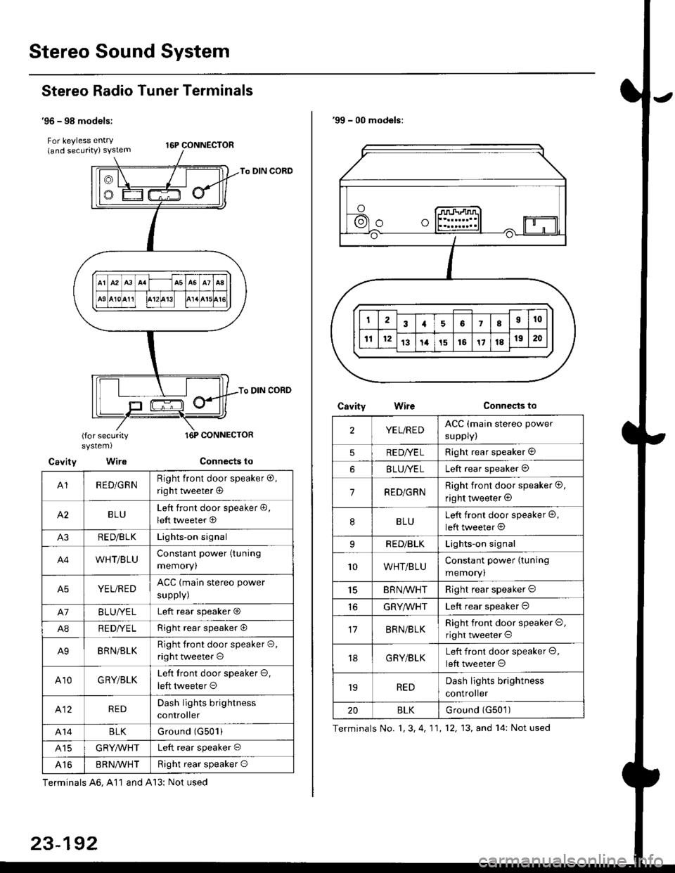
Stereo Sound System
Stereo Radio Tuner Terminals
'96 - 98 models:
For keyless entry . t6p coNNEcroR(and securrty) syslem
To DIN CORD
To DIN CORD
(for securitysystem)
Cavity Wire
A1RED/GRNRight front door speaker o,
right tweeter @
BLULeft front door speaker @,
left tweeter @
A3RE D/B LKLights-on signal
A4WHT/BLUConstant power (tuning
memoryl
A5YEL/REDACC (main stereo power
suppry)
A7BLUI/ELLeft rear speaker O
A8RE DI/E LRight rear speaker O
A9BRN/BLKRight front door speaker O,
right tweeter o
A10GRY/BLKLeft tront door speaker O,
left tweeter O
412REDDash lights brightness
controller
A14BLKGround (G501)
415GRYMHTLeft rear speaker O
Al6BR N/VVHTRight rear speaker O
Terminals A6, A11 and A13: Not used
23-192
'99 - 00 models:
CsvityConnccts toWire
2YEL/REDACC (main stereo power
suppry)
5RE DI/E LRight rear speaker @
BLUI/ELLeft rear speaker @
7RED/GRNRight front door speaker @,
right tweeter @
8BLULeft front door speaker @,
left tweeter @
9RED/BLKLights-on signal
10WHT/BLUConstant power (tuning
memory)
15BRN,ryVHTRight rear speaker O
GRYMHTLeft rear speaker O
17BRN/BLKRight front door speaker O,
right tweeter O
18G RY/BLKLeft front door speaker O,
left tweeter O
'19REDDash lights brightness
controller
20BLKurouno t(l5u t,
Terminals No. 1, 3, 4, 11,12, 13, and 14: Not used
Page 1696 of 2189
Power Windows
Master Switch Test (Coupe/Hatchbackl
1. Remove the master switch from the driver's door
panel (see page 23-2281.
Disconnect the 12P connector from the master
switch.
MAINSWITCH
Terminal side of male terminals
3. Check for continuity between the terminals in each
switch position according to the table.
Driver's Switch:
The driver's switch is combined with the control unit so
you cannot isolate the switch to test it. Instead. run the
master switch input test procedures at terminals 41. A3,
44. A8 and Al2 on page 23-226. lf the tests are normal,
the driver's switch must be faulty.
A1IA3A4A5
A1A8,/l/412
23-226
Passenger's Switch:
Terminal
P""*;l-m;\A2A5A6A7
OFFONo---o
OFFo---o
UPON
c'---o
o---o
OFFo---o
DOWNONo---o
--oo-
OFFo---o
Page 1697 of 2189
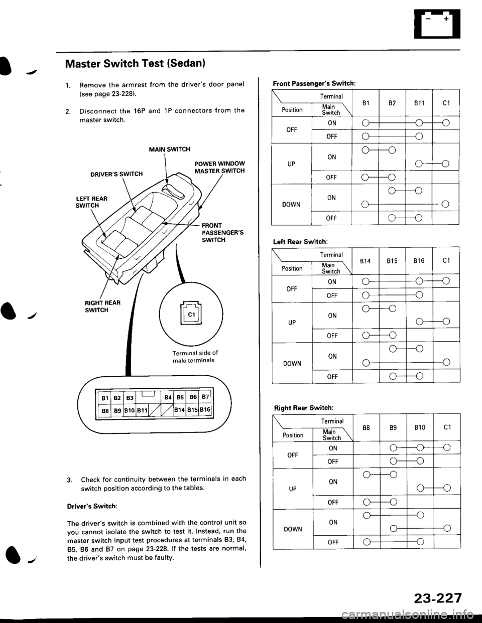
Master Switch Test (Sedan)
1.Remove the armrest from the driver's door panel
(see page 23-228).
Disconnect the 16P and 1P connectors from the
master switch.
Check for continuity between the terminals in each
switch position according to the tables
Driv€r's Switch:
The driver's switch is combined with the control unit so
you cannot isolate the switch to test it. Instead, run the
master switch input test procedures at terminals 83, 84,
85. BO and 87 on page 23-22A. lt the tests are normal,
the driver's switch must be faulty.
MAIN SWITCH
rFl
ll"'llt.:::::::l
B1B3B4B5B6B7
B889810811/l/leuBl5816
Terminalside of
male terminals
Front Passenger's Switch:
Terminal
P*,j--f$t,l"\B182811cl
OFFONCF--o
OFFooo
UPONo---o
o---o
OFFc\---o
DOWNON
o
oo
-o
OFFoo
Left Rear Swhch:
Terminal
P".r,-'-f-mn\814815816c1
OFFONG--o
OFFoo
UPONo--oo
o---o
OFFo-o
DOWNON
o-
o--o
o
OFFo--_o
Right Rear Switch:
Terminal
'**-T-*mB889B'�t0c1
OFFONo-o'o
OFFo---o
UPONo---o
CF--o
OFFCr---o
DOWNONo---.o
--oo-
OFFo---o
23-227