Page 1854 of 2189

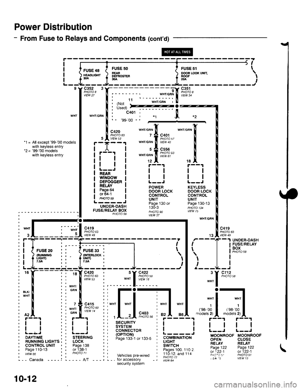
Power Distribution
- From Fuse to Relays and Components (cont'd)
FUSE 48HEAOL|SHT30A
c3s2 3
vtEw 27
WTIT/GFN
FUSF 50FEAFDEFBOSTEF30A
ooon r,ooxuxn \RooF -' I204
I
I
I
I
5t
FusE sr t
9l
;:$*fiit"rl.ru'"'""
I i*il
:::*ffi,
""'_[
tallt r--1 r--1
l-=Ji llll;i'ifr'ilrowi | | | |NEAN
DEFOGGER: L--J L--J
!EuI. ! powen KEYLEss
3g9F I oocin iocx DooR LocKI CONTROL CONTROLPHorobs ! Uttf UN|TL----J ii"j- , "n ^.UNDER-DASH r:d.r ppdro,uFUSETRELAY Box ;;;; "" ,!Fw /); - - - - - - ' - - - - - - - - - - I I P4atasa ;;"; i,
:-;-ry wHr/GFN
: I .-.-.i. -", I '-': :-'I "o''. I l "ott
i
";L____j_lU*?,?"
| .,"Iii;n*
: f'4. ii ;f' ii ,L-.-Ii"?,%' ;f5-"i4.-"'";5-{"'"r'!|L1
:! ! ::! ! :; 3$3i'9,1" r! ! I | | |
i l- l-
- - -
_:-
- ---------1 - - - - - - -
i I r'
- -
T
-
I F$r".',lP,XiI
ii{*"..0 ,' 1;;;il--l l | leox
i! ipp ii liuir'-*i |
')l 'l
l i' r--t-----'-.r--rL--------J- -------t I /---L-I
i
"
l-----l i ::[ir:;?:' i ::[?:+: |
"""1
'*'
i[.iiilr-il[-j,*---]d;1.*-;il;1,
:l I r:l I i: ts6'""?cro* i! ! L--i r--J
i ilr--,.ir...^.._^i I
'rr6-;i."
i: !:lJ',"#,",,*. i i.itc-,tr# Bgg,FooF u-oorinoor' RUNN|NG LrcHrs , ' LocK ; : ; !!gEr_.. ;;,1'y RELAYi cournol^urtr , i pase^138 :: i Swircn- -- Fj.Ti, pase 122, Paoe 110-13 or'138-1 Paoes 100. 110 2 -:Y;^:':;;;''"" :i ;hoi;,; ;: vehicrespre_wired ;!id-?iXioii.' glj:,';: ffl?3;1i,-- canada ----r l----A,/T ---,.-. for accessory -, |;r"*ir" .n 5 vtEvtl 13
10-12
secu.ity system
Page 1855 of 2189
ie----1
\{
i____J
WIIT/FED
FUSE 54OPNOI404
c351
vtEw 34
c419
FUSE 52HOAT. ST(IP LT154
c352
vlEw2/
FUSE 53NAZABO
c352
vtEw 27
c4't 1
UNDER-HOODFUSE/RELAYgox
15
_",":IWH'/BLK
(Not (Not 7Used) Used)
UNDER-DASHFUSE/RELAY BOXPHOTA 58
c419 C926110!0,63 oPTtoNCONNECTOBPHOTO 62
WHT/GRN
{with CruiseControl 4)
WHT
'9&'98 modelspre'wked toracteEsorysacurity system
""'l
o
;l10
vtEw 6a
cs16
'99'0O modelspre-wired foraccessorysecurfy system
SECURIrySYSTEMCONNECTOR(oPTroN)Page 133-4
ll
tl
BRAKESWITCHPages 23-4 , 24 4 ,25-4, 34-1, 39,39-4, 39-8, 39-12,44-2,110-15,110-16, 110 17,'138, and 138-1
ll
ll
HAZARDWARNINGswrTcHPage 110'6or 110-8vtEw 32
,rr rrRt3,:i]L-
SECURITYSYSTEMCONNECTOR(oPTlON)Page 133-4
r----=-:'l
I Uoll UonEcI I
tlL------JHORN BELAYPage 40, 40-1,ot 40-2
PHOTO 58 (96 97 models)PHOIo 129 (98 mode)
c447
wEw 5a
sEcuRrwSYSTEMCONNECTOR(oPTroN)Page 133
10-13
Page 1864 of 2189

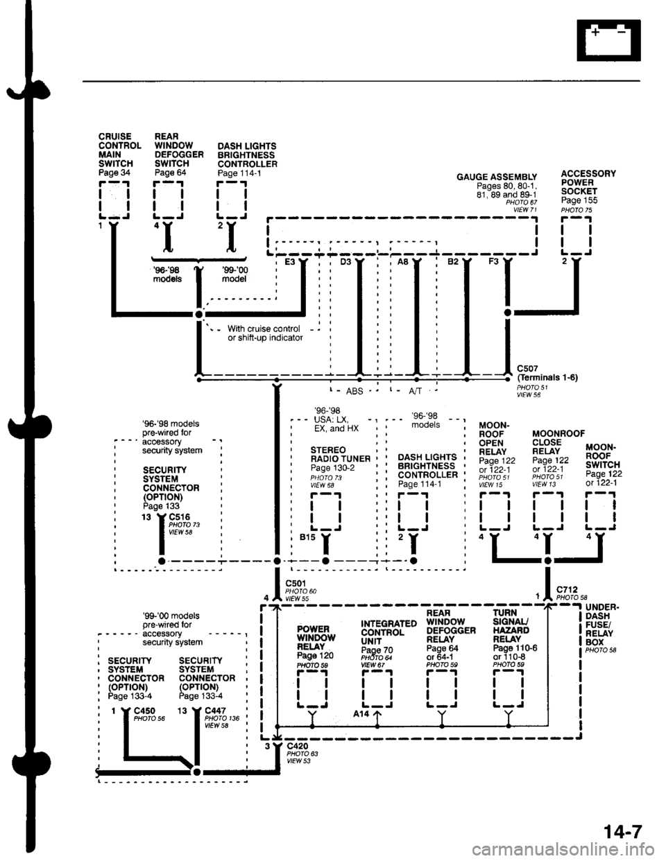
cRutsECONTROLMAINswrTcHPage 34
tl
ll
1Y
. - -' accessory
: security system :
i secun,rY ;
: SYSTEMi coNNEcroR :' (oPTroN)' Page |33
: '. rg;'3,, :, I vrfl,v 58
ili; . ----+
REARWINDOW DASH LIGHTSDEFOGGER BBIGHTNESSSWITCH CONTROLLER
:93' :gl"' Goug:*:FTi\" f3$??'o"'
llll bi:8d;fttie-i:9-9{EJ
aaal ,"|;fl9,,ff%;"
:f :1'L;,:;;-;__:_:::J
i:ir .:,;,-rr-E:
f
,-T,-"T-'-.
[_j,I=
,
lii
f ::'* ,I., l, I -l*,.Oerminals l '6)
'96-'98 modelspr+wi.ed tor
'99'00 modelspre-wired lor-_----accessory, security system
I srcunrw sEcunrrY :, SYSTEM SYSTEM ;i CONNECTOR CONi{ECTOR '' (oPTroN)
: Page 133-4
PHO|O136'
I- ABS -.
.-- USA: LX. -' .-' vo-Jl --', EX, and ilx mooers
vtEw 56
MOONROOF
!!P:',t MooN.
i*:r?, 33,o+"
'iii?,;) i??3;?'
' STEREO' RADTO TUNER ' ' DASH LIGHTS ,' P.da11o-, ' ' BRIGHTNESS '', ,;;;;- - : : coNTRoLLER '', v,iw;;" i i eage tte.t :, r-1 ,r r-1
: | | ::l I I
: | | ':l I. L-J . L-J
i"'r ii'I i
MOON-ROOFOPENRELAYPage 122ot 122-1
vtEw 15
ll
ll
'+--a ---'-*-'O
c50tPHOIO 60vtEw 55
r-1 r-1
tttl
lttlL-J L-J
,l
POWENwrNDowNELAYPage 120?HOm 59
ll
tl
.LIJ
14-7
Page 1922 of 2189

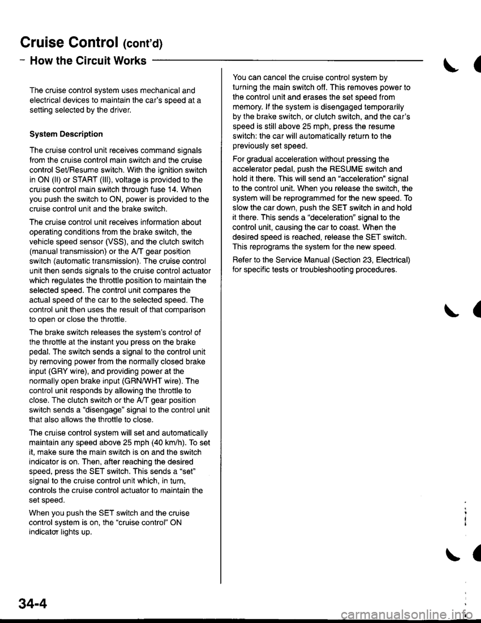
Gruise Control (cont'd)
- How the Circuit Works
The cruise control system uses mechanical and
electrical devices to maintain the car's sDeed at a
setting selected by the driver.
System Description
The cruise control unit receives command signals
from the crurse control main switch and the cruise
control SeVResume switch. With the ignition switch
in ON (ll) or START (lll), voltage is provided to the
cruise control main switch through fuse 14. When
you push the switch to ON, power is provided to the
cruise control unit and the brake switch.
The cruise control unit receives information about
operating conditions from the brake switch, the
vehicle speed sensor (VSS), and the clutch switch
(manual transmission) or the A,/T gear position
switch (automatic transmission). The cruise control
unit then sends signals to the cruise control actuator
which regulates the throttle position to maintain the
selected speed. The conlrol unit compares the
actual speed of the car to the selected speed. The
control unit then uses the result of that comoarison
to open or close the throttle.
The brake switch releases the system's control of
the throttle at the instant you press on the brake
pedal. The switch sends a signal to the control unit
by removing power from the normally closed brake
input (GRY wire), and providing power at the
normally open brake input (GRN/vVHT wire). The
control unit responds by allowing the throttle to
close. The clutch switch or the A,/T gear position
switch sends a "disengage" signal to the control unit
that also allows the throttle to close.
The cruise control system will set and automatically
maintain any speed above 25 mph (40 km/h). To set
it, make sure the main switch is on and the switch
indicator is on. Then, after reaching the desired
speed, press the SET switch. This sends a "set"
signal to the cruise control unit which, in turn,
controls the cruise control actuator to maintain the
set speed.
When you push the SET switch and the cruise
control system is on, the "cruise control" ON
indicator lights up.
34-4
(
You can cancel the cruise control system by
turning the main switch off . This removes power to
the control unit and erases the set speed from
memory. lf the system is disengaged temporarily
by the brake switch, or clutch switch, and the car's
speed is still above 25 mph, press the resume
switch: the car will automatically return to the
previously set speed.
For gradual acceleration without pressing the
accelerator pedal, push the RESUME switch and
hold it there. This will send an "acceleration" signal
to the control unit. When you release the switch, the
system will be reprogrammed for the new speed. To
slow the car down. oush the SET switch in and hold
it there. This sends a "deceleration" signal to the
control unit, causing the car to coast. When the
desired speed is reached, release the SET switch.
This reprograms the system tor the new speed.
Refer to the Service Manual (Section 23, Electrical)
tor specific tests or troubleshooting procedures.
(
a
Page 1939 of 2189
Horn
- '96-'97 Models
UNDER.HOODFUSE/RELAYBOX
c353PHOTOs
See PowerOistribution,pag610-13.""^T.!,-
HORNRELAYPHA|O 58
c214
vtEw21
BLU/FEO
1
VHT/qRN
I1
WHT/qRN
: :i-I:::--li i ! !'-'! fevtess
! a;fi."*
,,lr--J I::.-------J. , STEREO RAOIO TUNER
| | vtEw 68
HORN
l
h: c4o1PHQ|A 57
c430
Sse CruiseControl
Vehicles pre-wired ---lor accessorysecurity system
BLU
GBY
------- J
- -.! STEERINGWHEEL
6 g c411
| _vtEw 60
a,---li
cnv I
18 A C516
sEcuRtwSYSTEMCONNECTOR(oPTroN)PHO|O 73VEW 5A
40
Page 1941 of 2189
Horn
- '99-'00 Models
FUSE 52HORI,SfOP LTt5a
UNDER.HOODFUSE/RELAYBOX
HORNRELAY
2
BIU/FED
Ior
GRY
.,1 ,
J---a-----r---O
i ;l i ;,1...,' r--1 : SECUR|TY:ll:sYsrEM,ia,coNNEcroR' ! ! (oPrloN), L--J , i!,o!o 73, KEYLESS I vlEw 58
: DooR LocK withi coNTRoL Kevless, UNIT EntryI PHOIO 134I vtEw 75
i o.--------;
:T:' cnvl :
i"l ii ri-'--.| coMBtNATtoN
: lrft ! !',f,11" I' | | puotozz :', l--J vttw u ;
i--- Er""pt ex.ooer ----j
c214
v|EW21
c430PHOTO 65
Vehicles pre-wired foraccessory security system
STEERINGWHEEL
CABLEREEL
.l
I
I
I
ISee CruiseControl
GRY
ELU
I
a\
I
GRY
HORN
---------^1
niffil"a!m"
40-2
Page 1946 of 2189

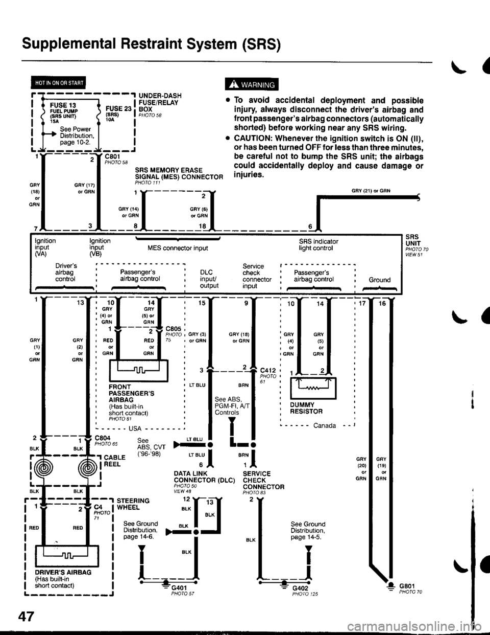
Supplemental Restraint System (SRS)
(
FUSE 13FUELPUUPFBA UMT)15A
See PowerDistibution,page 10-2.
FUSE 23(sRs)
c801PHOTO 58
SRS MEMORY ERASESTGNAL (MES) CONNECTORPHO|O 111
. To avoid accidental deployment and possible
iniury always disconnect the driver's airbag and
f ront passenger's airbag connectors (automatically
shorted) before working near any SRS wiring.
. CAUTION: Whenever the ignition switch is ON (tt),
or has been turned OFF for less than three minutes,
be caretul not to bump the SRS unit; the airbags
could accidentally deploy and cause damage or
iniuries.
UNDER-DASHFUSE/RELAYBOX
GFY 07)or GFN{18)
GFN
GFYt2l
GFN
GRY0)
GFN
2
ALK
J (ii
t\
GFY O4)or GRN
SRSUNIT
a
-ffiffi,*l-{
H!=";=_J
iffii'r:fi:*" i tH-
PHOIO 125short contact) | - FCqOtL_________J PHO|A 57
47
GAY (21) or GRN
lgnitionInput(VA)
Driver's
cont.ol
lgnitioninput(VB)MES connector inputSRS indicatorlighl control
Service t------check : Passengefs ;connector ; airbag control , GroundInpu , /+rr I pir-r
Passenger'sai|bag conlrol; prc..t rnpuv, Ourpul
14GRY(5) orGFN
rffi{{_ilil
i ffi i""'"1*"o,"'.1'' i lffil
ffirtu!-T:l
ir:r*::"."
ilstEl'{s6.e8'�
'"'Jl "Tl
, I oATA L|NK SERVTCE: CoNNECTOR (DLC) CHECK,J piarasa CONNECTORvtEw48
Page 1954 of 2189
A/C Compressor Controls
- AllModels
cc5)M7
BLU/RED
?
\a
@
&cCOMPRESSORCLUTCHRELAYPHOfO 10
a
! ,acc, : POWERTRATN! arn.^-^,o..^, I or ENGINE
! ii i"i-iiii"v i.,ii.r | fi 3$18.
I A/C request ! (pCM or ECM)I (ACSJ a pHOrO a6L------J vtEw 70
REO
BEO
1
RED
BLU/FEO
2
BLU/FEO
ct31
:"1'!i'------;
Fi:rz, a ='e6-'s8: A|| moders except D1685vtEw 21 '99100: D16Y5 with l\illT'* = 96-'98: All models
ir'iio ," 99. 00: Dt6y5 wth t\4/t Dl6Bb
atcPRESSUREswtTcH
c752
c1
".,n""t 1(
".r-".rf, "tA% "
"."-:,fi tfr,]4.
v
To facing page ('96''98 models)or page 62'2 ( 99-'00 models).
-Yl
-t---------Jc353
c2'14
vtEW21
c209
A,/CCOMPRESSORCLUTCH
COMPRESSORTHERMALPROTECTOR
UNDER-HOODFUSE/RELAYBOXf-T-*-'.T'---l H53.',EPA?' i-l-------
i iflH* !F,?r",, i f6F"'.i:.",",
| tsBi":J;"#il ! a T| | oaoe 1o-9. ! I I See PowerL_J1_j:_-_j ! H Distriburion.e Y c42o i I
pase 1o-1.
***
f ifi"l'
^ see power ! |
62
!(on bracket)