1996 HONDA CIVIC acc control
[x] Cancel search: acc controlPage 694 of 2189

Description
Electronic Control System {cont'dl
Ascending Control
When the PCM determines that the vehicle is climbing a hill in E position, the system oxtends the sngagement area of2nd gear and 3rd gear to prevent ths transmission from fr€quently shifting between 2nd and 3rd gears, and between 3rdand 4th gears, so the vehicle can run smooth and have more power when needed. There are two ascending modes withdifferent 3rd gear driving areas according to the magnitude of a gradient stored in the pCM.
NOTE:
. The PCM memory contains shift schedules between 2nd and 3rd gears, and between 3rd and 4th gears that enable thePCM's fuzzy logic to automatically select the most suitable gear according to the magnitude of a gradient. Fuzzy logic is a form of artificial intelligence that lets computers respond to changing conditions much like a humanmind would,
Dssconding Control
When the PCM determines that the vehicle is going down a hilt in E position, the shift-up speed from 3rd to 4th gearwhen th€ throftle is closed becomes faster than the set speed for flat road driving to widen the 3rd gear driving area.This, in combination with engine braking from the deceleration lock-up, achieves smooth driving when the vehicle isdescending. There are two descending modes with different downshift (4 - 3) schedules according to the magnitude of agradient stored in the PCM. When the vehicle is in 4th gear, and you are decelerating on a gradual hill, or when you areapplying the brakes on a steep hill, the transmission will downshift to 3rd gear. When you accel6rate, the transmission willthen return to 4th gear.
ASCENDING MODEDESCENDING MODE
4TH SHIFTING
L.
F
CHARACTERISIICSCONTROL AREA
ff.1"11", vehicr. 3pe€dff;Tlr., vohicre speed
GRADUAL ASCENOINGCONTROL AREA
Docel6ration Control
When the vehicle goes around a corner. and needs to first decelerate and then accelerate. the rcM sets the data for decelerationcontrol to reduce the number of times the transmission shifts. When the vehicle is decelerating from speeds above 26 mph(41 km/h), the rcM shifts the transmission from 4th to 2nd earlier than normal to cope with upcoming acceleration.
14-16
Page 697 of 2189

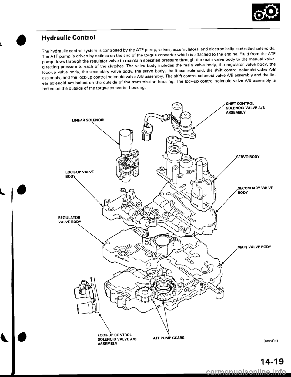
Hydraulic Control
The hydraulic control system is controlled by the ATF pump, valves, accumulators, and electronically controlled solenoids'
TheATFpUmpisdrivenbysp||nesontheendofthetorqueconverterWhichisattachedtotheengine.F|uidfromtheATF
pumpf|owsthroughtheregu|atorva|vetomajntainspecifiedpressurethroughthemainva|vebodytothemanuaIva|ve'
directingpressuretoeachofthec|utches.Theva|vebodyinc|udesthemainvaivebody,theregu|atorvalvebody,the
|ock-upva|vebody,thesecondaryVa|vebody,theservobody,theIinearso|enoid,theshiftcontro|so|enoidva|velVB
assembly, and the lock up control solenoid valve A/B assembly. The shift control solenoid valve Ay'B assembly and the lin-
ear solenoid are bolted on the outside of the transmission housing. The lock-up control solenoid valve A,/B assembly is
bolted on the outside of the torque converter housing
SHIFT CONTROLSOLENOIO VALVE A/8
ASSEMBLY
LINEAR SOLENOID
SERVO BOOY
REGULATORVALVE BODY
VALVE
VALVE BOOY
(cont'd)
CONTROLSOLENOID VALVE A/BASSEMBLY
ATF PUMP GEARS
14-19
Page 700 of 2189

Description
Hydraulic Control (cont'dl
Regulator Valve
The regulator valve maintains a constant hydraulic pressure from the ATF pump to the hydraulic control system, whitealso furnishing fluid to the lubricating system and torque converter. The fluid from the ATF pump flows through B and 8,.The regulator valve has a valve orifice. The fluid entering from B flows through the orifice to the A cavity. This pressure ofthe A cavity pushes the regulator valve to the right side, and this movement of the regulator valve uncovers the fluid portto the torque converter and the relief valve. The fluid flows out to the torque converter, and the relief valve and regulatorvalve moves to the left side. According to the level of the hydraulic pressure through B, the position of the regutator vatvechanges and the amount of the fluid from B' through D and c also changes. This operation is continued. maantaining theline pressure,
NOTE: When used. "|eft" or "right" indicates direction on the illustration betow.
ENGINE NOT RUNNING
TOROUE CONVERTER
ENGINE RUNNING
To TOROUE CONVERTER Lubrication
Stator Roaction Hydraulic Prossur6 Control
Hydraulic pressure increases according to torque, are performed by the regulator valve using the stator torque reaction.The stator shaft is splined with the stator in the torque converter, and its arm end contacts the regulator sprang cap. whenthe vehicle is accelerating or climbing (Torque Convert€r Range), the stator torque reaction acts on the stator shaft, andthe stator arm pushes the regulator spring cap in the direction of the arrow in proponion to the reaction. Jne stator reac-tion spring compresses, and th€ reoulator valve moves to increase the line pressure which is regulated by the regulatorvalve. The line pressure reaches its maximum when the stator torque reaction reaches its maximum.
STATOR SHAFT ARM
REGULATOR VALVE
14-22
STATORATOR SHAFT ARM
SPRING CAP
Page 702 of 2189

Description
Hydraulic Flow
General Chart ol Hydraulic PressureATF Pump- pegurator varve -_l- Line pressure -f- Modurator pressure - Linear sorenoid
| -Clutch pressure
-Torque Converter pressure
t-Lubrication Pressure
Distribution of Hydraulic Pressur€. Regulator Valve -]- Torque Converter pressure
F_ Lubrication pressure
i- To regulate Line pressure
. Manual valve _ To select Line pressure _ clutch pressure
' Modulator Valve i/odulator pressure _ ___f_ Shift Control Solenoid Valves
F_ Lock_up Control Solenoid ValvesL_ Linear Solenoid
. 1-2 Shift Valve - l. 2-3 Shift Valve - 1- Ctutch pressure. 3-4 Shift Valve
lra
PORT NO.DESCRIPTION OF PRESSUREPORT NO.DESCRIPTION OF PRESSUREPORT NO.DESCRIPTION OF PRESSURE
1LINE6B
MODULATE(SHIFT CONTROL
SOLENOID VALVE B)
414TH CLUTCH
LINEMODULATE(LOCK-UP CONTROL
SOLENOID VALVE A)
56LINEAR SOLENOID
LINE6D
MODULATE(LOCK-UP CONTROL
SOLENOID VALVE B)
90TOROUE CONVEBTER
2LINE6D'
MODULATE
(LOCK-UP CONTROL
SOLENOID VALVE B)
91TOROUE CONVERTER
LINE7LINE92TOROUE CONVERTERLINE8LINE/CPC93ATF COOLER3"LINE9LINE94TOROUE CONVERTER4LIN E'101ST CLUTCH95LUBRICATION
LINE202ND CLUTCHYOTOROUE CONVERTERLINE20A2ND ACCUMULATOR97TOROUE CONVERTER5LINE99SUCTION
MODULATE303RD CLUTCHXDRAIN
6A
MODULATE(SHIFT CONTROL
SOLENOID VALVE A)
404TH CLUTCH
14-24
Page 705 of 2189

E! or l8! Position
1. lst Gear
The flow of fluid through the torque converter circuit is same as in E position, The line pressure tlows to the manual
valve and the modulator valve. The line pressure changes to the modulator pr€ssure (6) at the modulator valve and to
the line pressure (4) at the manual valve. The modulator pressure (61 flows to the lsft end of the 1-2 shift valve and the
3-4 shift valve because shift control solenoid valve A is turned OFF and B is turned ON by the PCM. The 1-2 shift valve
is moved to the right side. The line pressure (4) changes to the lst clutch pressure (10) at the 1-2 shift valve and the
oritice. The lst clutch pressure (10) is applied to the 1st clutch and tho 1st accumulator; consquently, the vehicle will
move as the engine power is transmitted.
NOTE: When used, "|eft" or "right" indicates direction on the hydraulic circuit'
(cont'd)
14-27
Page 712 of 2189

Description
Lock-up System (cont'd)
TOROUE CONVERTER
In B.rl position, in 3rd and 4th, and lDl_- position in 3rd.pressurized fluid is drajned from the back of the torqueconverter through a fluid passage. causing the lock-uppiston to be held against the torque convener cover. Asthis takes place, the mainshaft rotates at the same speedas the engine crankshaft, Together with the hydrauliccontrol, the PCM optimized the timing of the lock_upsystem. Under certain conditions, the lock_up clutch isapplied during deceleration, in 3rd and 4th gear.
The lock-up system controls the range of lock_up accord_ing to lock-up control solenoid valves A and B. and thelinear solenoid. When lock-up control solenoid valves Aand B activate, modulator pressure changes. Lock_upcontrol solenoid valves A and B and the linear solenoidare mounted on the outside of the torque converterhousing. and are controlled by the pclvl.
Lock-up Conditions/Lock-up Control Solenoid Valves/Linear Solenoid Pressure
MODULATOR PRESSURE
.-- LINEAR SOLENOID PRESSURE
LOCK.UP CONTROL. VALVE
LOCK.UP CONTROLSOLENOID VALVELock-up
Conditions
Lock-up Control
Solenoid ValveLineal
Solenoid
PressureAB
Lock-up OFFOFFOFFHig h
Lock-up. HalfONDuty operation
OFF - ON
Lock-up. FullONONHigh
Lock-up
during
decelerationONDuty operation
OFF * ONLowTOROUE CONVERTERCHECI( VALVE
RELIEF VAI-VE
LOCK.UP TIMINGVALVE
^ r______rr r cooLER RELTEF VALVE
t'-
14-34
ATF PUMP
Page 715 of 2189

TOROUE CONVERTER
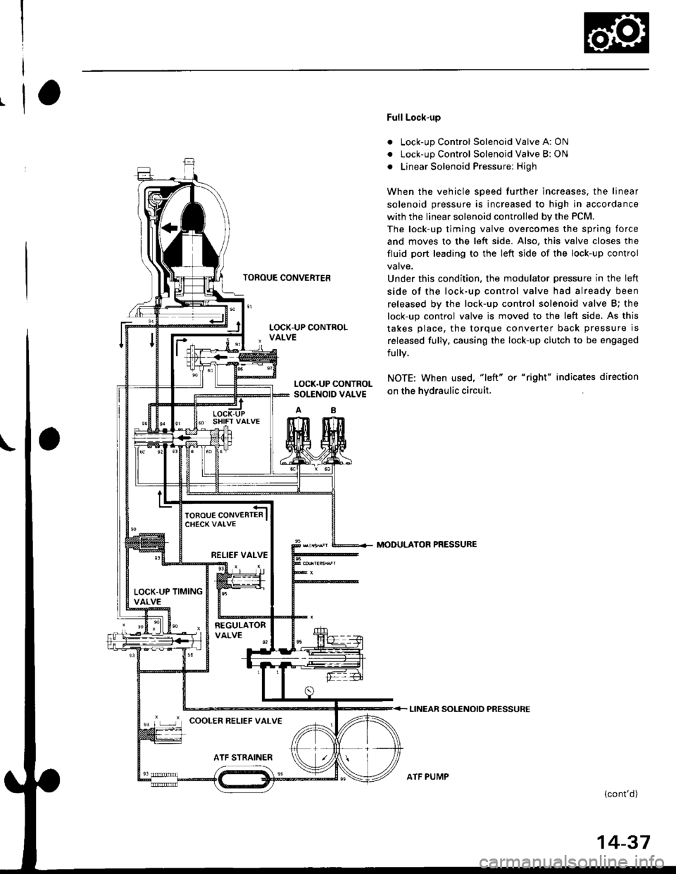
Full Lock-up
. Lock-up Control Solenoid Valve A: ON
. Lock-up Control Solenoid Valve B: ON
o Linear Solenoid Pressure: High
When the vehicle speed further increases. the linear
solenoid pressure is increased to high in accordance
with the linear solenoid controlled bv the PCM.
The lock-up timing valve overcomes the spring force
and moves to the left side. Also, this valve closes the
fluid port leading to the left side of the lock-up control
Under this condition. the modulator pressure in the left
side of the lock-up control valve had already been
released by the lock-up control solenoid valve B; the
lock-up control valve js moved to the left side. As this
takes place, the torque converter back pressure is
released fully. causing the lock-up clutch to be engaged
fully.
NOTE: When used, "|eft" or "right" indicates direction
on the hvdraulic circuit.
MODULATOR PRESSURE
LINEAR SOLENOIO PRESSURE
{cont'd)
LOCK.UP CONTROLSOLENOID VALVE
RELIEF VALVE
LOCK.UP TIMINGVALVE
'r ,-.r' cooLER RELTEF vALvE
ATF PUMP
14-37
Page 721 of 2189

I
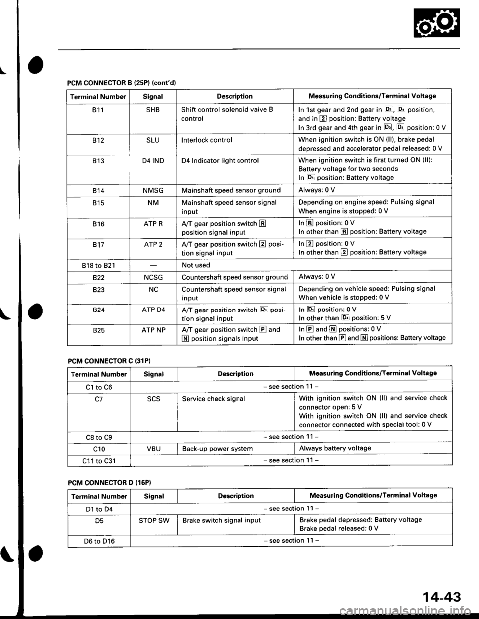
PCM CONNECTOR B {25P1 {cont'dl
Terminal NumberSignalDescriptionMeasuring Conditions/Terminal Vohage
811SHBShift control solenoid valve B
control
In 1st gear and 2nd gear in -q1, q11 position,
and in E] position: Battery voltage
In 3rd gear and 4th gear in lD.J, [Dr- position: 0 V
B't2SLUInterlock controlWhen ignition switch is ON (ll), brake pedal
deoressed and accelerator Dedal released: 0 V
813D4 INDD4 Indicator light controlWhen ignition switch is first turned ON (ll):
Battery voltage for two seconds
In E position: Baftery voltage
B't 4NMSGMainshaft speed sensor groundAlways: 0 V
E tcNMMainshaft speed sensor signal
input
Depending on engine speed: Pulsing signal
When engine is stopped: 0 V
816ATP RAy'T gear position switch Eposition signal input
InE position: 0V
In other than E position: Battery voltage
817ATP 2A/T gear position switch E posi-
tion signal input
InE position: 0V
In orher than E position: Battery voltage
818 to 821Not used
s22NCSGCountershatt speed sensor groundAlwaysr 0 V
B�23NCCountershaft speed sensor signal
input
Depending on vehicle speed: Pulsing signal
When vehicle is stopped: 0 V
B�24ATP D4Ay'T gear position switch lor posi-
tion signal input
InEposition:0V
In other than 6 position: 5 V
ATP NPA,/T gear position switch E and
N position signals input
InE and E positions: 0V
In otherthan E and N] positions: Battery voltage
PCM CONNECTOR C {31P)
Terminal NumberSignalDescriptionMeasuring Conditions/Terminal Voltage
Cl to C6- see section 11 -
c1Service check signalWith ignition switch ON (ll) and service check
connector oDen; 5 V
With ignition switch ON (ll) and service check
connector connected with sDecial tool: 0 V
C8 to Cg- see section 11 -
c10VBUBack-up power systemAlways battery voltage
C11 to C31- see section '11 -
PCM CONNECTOR D (16P}
Terminal NumberSignalDescriptionMeasuring Conditions/Terminal Voltage
Dl to D4- see section 11 -
D5STOP SWBrake switch signal inputBrake pedal depressed: Battery voltage
Brake pedal released: 0 V
D6 to D16- see section 1 l -
14-43