1996 HONDA CIVIC ESP
[x] Cancel search: ESPPage 1076 of 2189
System Description
Steering Gearbox
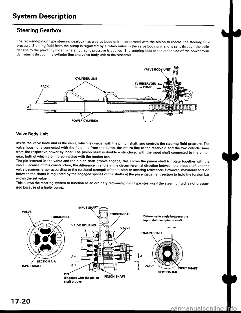
The rack-and-pinion type steering gearbox has a valve body unit incorporated with the pinion to control the steering fluidpressure. Steering fluid from the pump is regulated by a rotary valve in the valve body unit and is sent through the cylin,der line to the power cylinder, where hydraulic pressure is applied. The steering fluid in the other side of the power cylin,der returns through the cylinder line and valve body unit to the reservoii.
VALVE EODY UNIT
CYLINDER LINE
To RESERVOm +-From PUMP -;
POWER CYLINDER
Valve Body Unit
Inside the valve body unit is the valve, which is coaxial with the pinion shaft, and controls the steering fluid pressure. Thevalve housing is connected with the fluid line from the pump, the return line to the reservoir, and the two cylinder linesfrom the respective power cylinder. The pinion shaft is double - structured with the input shaft connected to the piniongear, both of which are interconnected with the torsion bar.
The pin inserted in the valve and the pinion shaft groove engage; this allows the pinion shaft to rotate together with thevalve. Because of this construction, the difference in angle in the circumferential direction between the input shaft and thevalve becomes larger according to the torsional strength of the pinion or steering resistance. However, maximum torsionbetween the shafts is regulated by the engaged splines of the shafts at the pin engagement section to hold the torsion barwithin the set value,
This allows the steering system to function as an ordinary rack-and-pinion type steering if the steering fluid is not pressur-
ized because of a faulty pump,
VALVE
Difforence in angle botwoon theinput shaft and pinion shsft
PINION SHAFT
lo
INPUT SHAFT
-l
a
17-20
INPUT SHAFT
Page 1095 of 2189
Power Steering Hoses, Lines
Fluid Leakage Inspection
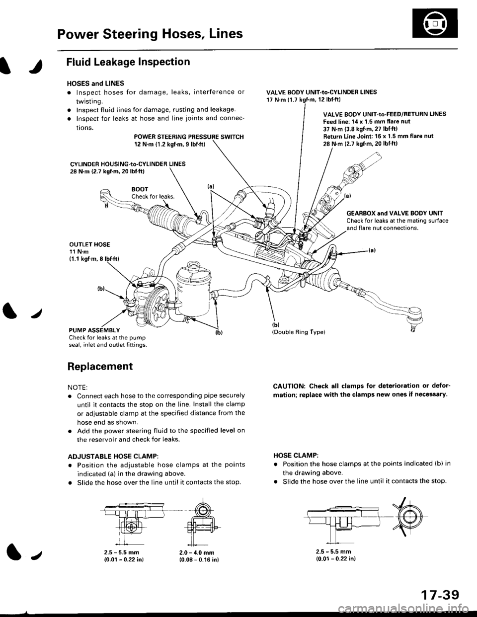
HOSES and LINES
. Inspect hoses for damage, leaks, interference or
twisting.
. Inspect tluid lines for damage, rusting and leakage.
. Inspect for leaks at hose and line joints and connec-
tions.
POWER STEERINGswtTcH12 N.m {1.2 kgt.m,9lbt.ft}
CYLINDER HOUSING-to.CYLINDER LINES28 N.m (2.7 kgf.m, 20 lbf.ft)
VALVE BODY UNIT-to-CYLINDER LINES'17 N.m {1.712 tbl.ftl
VALVE BODY UNIT-Io-FEED/RETURN LINES
Feed line: 14 x '1.5 mm llare nut
37 N.m {3.8 kgJ.m, 27 lbf'tt)
Return Line Joint 16 x 1.5 mm flare nut
28 N m 12.7 kgf.m,20 lbtft)
HOSE CLAMP:
. Position the hose clamps at the points indicated (b) in
the drawing above.
. Slide the hose over the line until it contacts the stop.
8()07Check for leaks.
OUTLET HOSE11 N.m
G€AR8OX and VALVE BODY UNITCheck for leaks at the mating surfaceand flare nut connections,
tbt(Double Ring Typei
CAUTION: Check all clamps for deterioration or delor-
mation; replace with the clamps new ones il necessary.
(1.1 kgf.m,8
PUMP ASSEMBLYCheck for leaks at the pump
seal, inlet and outlet fiftings.
Replacement
NOTE:
. Connect each hose to the corresponding pipe securely
until it contacts the stop on the line. Install the clamp
or adiustable clamp at the specified distance from the
hose end as shown.
. Add the power steering fluid to the specified level on
the reservoir and check for leaks.
ADJUSTABLE HOSE CLAMP:
. Position the adiustable hose clamps at the points
indicated (a) in the drawing above.
. Slide the hose over the line until it contacts the stop.
2.5 - 5.5 mm{0.01 - 0.22 in)2.0 - 4.0 mm(0.08 - 0.16 in)
2.5 - 5.5 mm(0.01- 0.22 in)1.,
17-39
Page 1099 of 2189
I
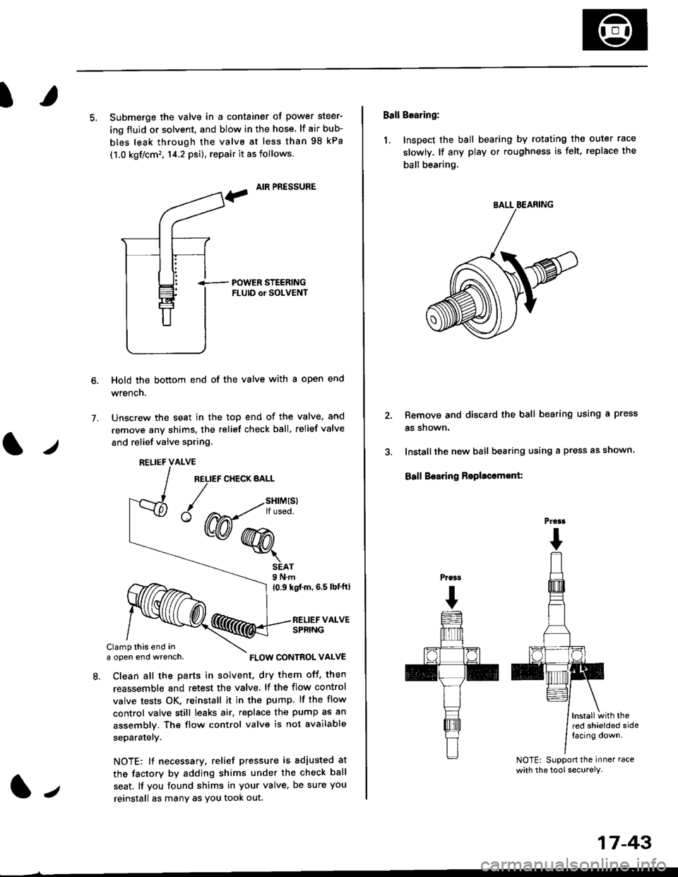
5, Submerge the valve in a container of power steer-
ing fluid or solvent. and blow in the hose. lf air bub-
bles leak through the valve at less than 98 kPa
(1.0 kgf/cm'�, 14.2 psi), repair it as follows.
, AIR PRESSURE
?
i-- POWER STEERTNGFLUID or SOLVENT
Hold the bottom end of the valve with a open end
wrench.
Unscrew the seat in the top end of the valve. and
remove any shims, the relief check ball. relief valve
and relief valve spring.
7.
l./
RELIEF CHECK BALL
1.,
SEAT9 N.m
{0.9 kgf'm, 6.5 lbt'ftl
RELIEF VALVESPRING
Clamp this end ina open end wrench,
8. Clean all the parts in solvent, dry them off, then
reassemble and retest the valve. lf the flow control
valve tests OK, reinstall it in the pump. lf the flow
control valve still leaks air, replace the pump as an
assembly. The flow control valve is not available
separatelY.
NOTE: 11 necessary, relief pressure is adjusted at
the factorv by adding shims under the check ball
seat. lf you found shims in your valve, be sure you
reinstall as many as You took out.
RELIEF VALVE
{W-*"'
FLOW CONTROL VALVE
17-43
Ball Bearing:
1. Inspect the ball bearing by rotating the outer race
slowly. lf any play or roughness is felt, replace the
ball bearing.
Remove and discard the ball bearing using a press
as snown.
Installthe new ball bearing using a press as shown.
Ball Boaring Rsplaccmont:
lnstallwith thered shielded sidefacing down.
NOTE: Support the inner race
with the tool securely.
BALL BEARING
Prcrt
Page 1113 of 2189
I
14.
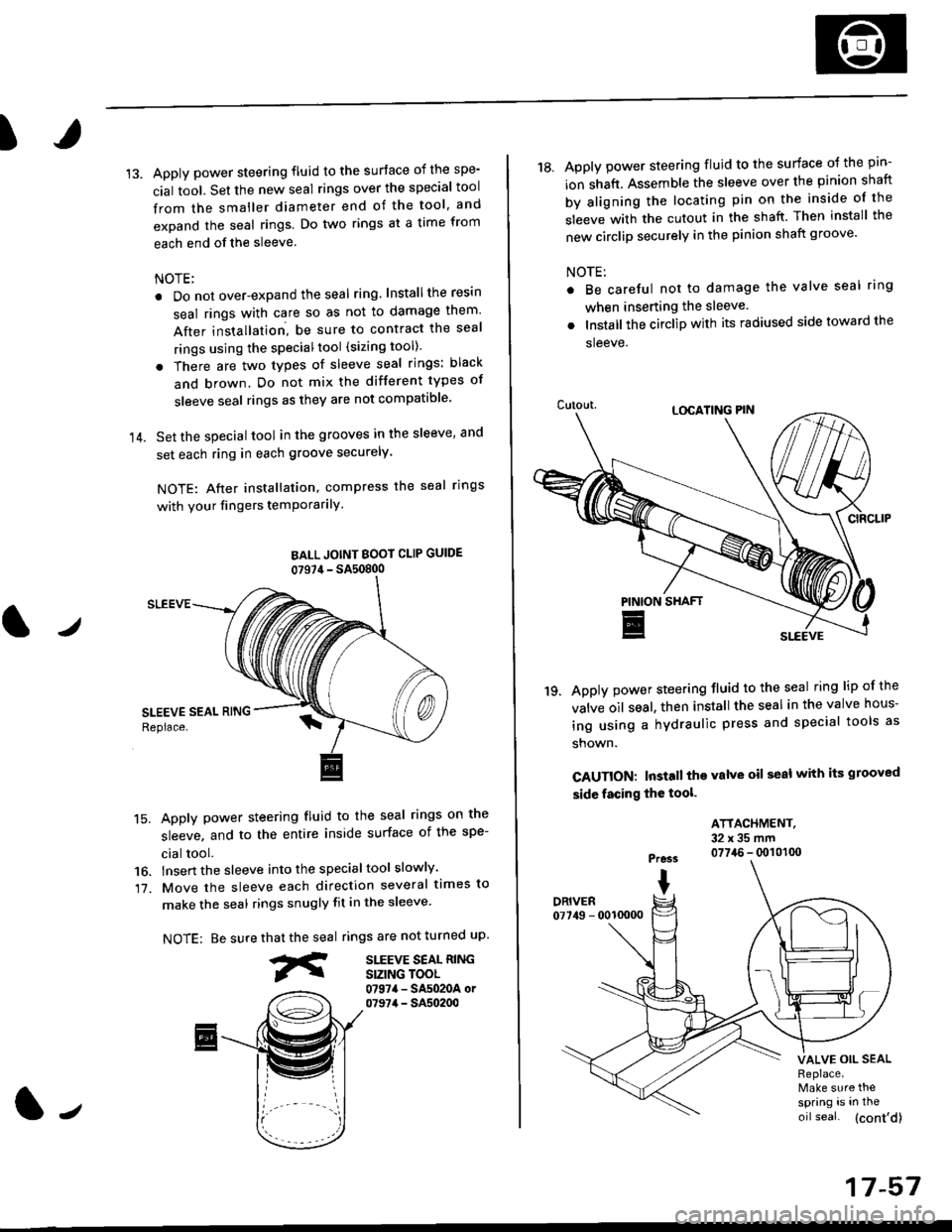
Apply power steering fluid to the surface of the spe-
cial tool. Set the new seal rings over the special tool
from the smaller diameter end of the tool, and
expand the seal rings. Do two rings at a time from
each end of the sleeve.
NOTE;
. Do not over-expand the seal ring. Installthe resin
seal rings with care so as not to damage them'
After installation, be sure to contract the seal
rings using the specialtool (sizing tool).
. There are two types of sleeve seal rings: black
and brown. Do not mix the different types of
sleeve seal rings as they are not compatible
Set the special tool in the grooves in the sleeve, and
set each ring in each groove securely.
NOTE: After installation, compress the seal rings
with your fingers temPorarilY
BALL JOINT BOOI CLIP GUIDE
07S7,1- SA50800
SLEEVE
15. Apply power steering fluid to the seal rings on the
sleeve, and to the entire inside surface of the spe-
cial tool.
16. lnsert the sleeve into the specialtool slowly'
17. Move the sleeve each direction several times to
make the seal rings snugly fit in the sleeve'
NOTE: Be surerings are not turned uP.
SITEVE SEAL RINGSIZING TOOL0797a - SA5020A or07974 - SA50200
that the seal
fr
J
17-57
18. Apply power steering fluid to the surface o{ the pin-
ion shaft. Assemble the sleeve over the pinion shaft
by aligning the locating pin on the inside of the
sleeve with the cutout in the shaft. Then install the
new circlip securely in the pinion shaft groove'
NOTE:
Be careful not to damage the valve seal ring
when inserting the sleeve.
Installthe circlip with its radiused side toward the
sleeve.
Apply power steering fluid to the seal ring lip of the
valve oil seal. then install the seal in the valve hous-
ing using a hydraulic press and special tools as
shown.
CAUTION: Install the valve oil seal with its grooved
side facing the tool.
'19.
ATTACHMENT.32x35mm0774.6 - q)101(x)Pre3s
IDRIVER07749 - 0010000
VALVE OIL SEALReplace.Make sure thespring is in the
oil seal. (cont'd)
Page 1115 of 2189
)
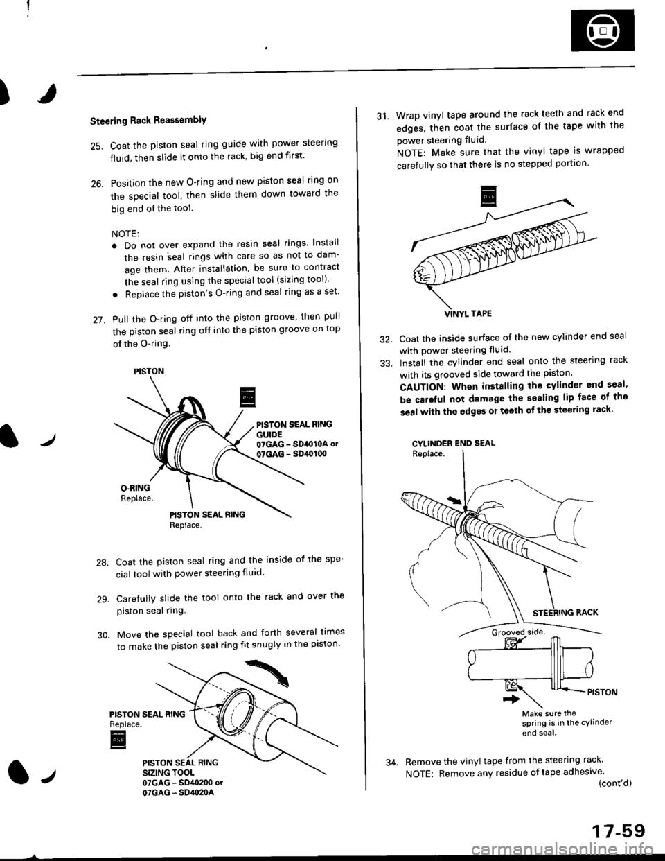
Steering Rack Reassembly
25. Coat the piston seal ring guide with power steering
fluid, then slide it onto the rack, big end first'
26. Position the new O-ring and new piston seal rlng on
the special tool, then slide them down toward the
big end of the tool
NOTE:
. Do not over expand the resin seal rings lnstali
the resin ;eal rings with care so as not to dam-
age them. After installation, be sure to contract
the seal ring using the specialtool (sizing tool)
. Replace the piston's O-ring and seal ring as a set'
27. Pull the O-ring off into the piston groove, then pull
the piston seal ring off into the piston groove on top
ol the O-ring
PISTON SEAL RINGGUIDE07GAG - SD4O10A ol
07GAG - SD,ol(xt
Coat the piston seal ring and the inside of the spe-
cial toolwith power steering fluid.
Carefully slide the tool onto the rack and over the
piston seal ring.
Move the special tool back and forth several times
to make the piston seal ring fit snugly in the piston'
PISTONReplace.
E
PISTON
31. Wrap vinyl tape around the rack teeth and rack end
edges, then coat the surface of the tape with the
power steering fluid
NOTE: Make sure that the vinyl tape is wrapped
carefully so that there is no stepped portion
Coat the inside surface of the new cylinder end seal
with power steering fluid.
Install the cylinder end seal onto the steering rack
with its grooved side toward the piston.
CAUTION: When installing the cylinder end seal,
be caieful not damage the sealing lip face of tho
seal with the edgss or teeth of th€ ste€ring rack'
CYLINDER END SEAL
Make sure thesPring is in the cylinder
end soal
Remove the vinyl tape from the steering rack
NOTE: Remove any residue oftape adhesive(cont'dl
17-59
Page 1117 of 2189
)
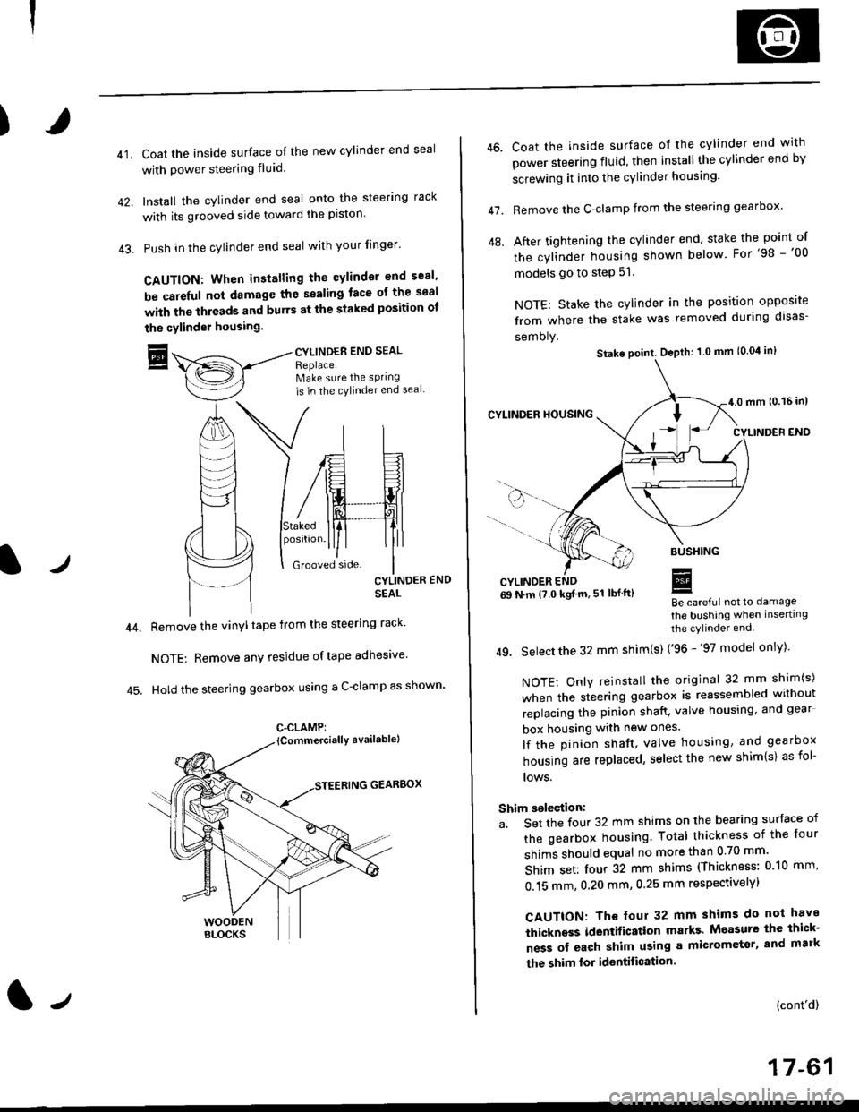
41.Coat the inside surface of the new cylinder end seal
with power steering fluid.
Install the cylinder end seal onto the steering rack
with its grooved side toward the piston'
Push in the cylinder end seal with your finger'
CAUTION: When installing the cylinder end sesl'
be carelul not damage the sealing face ot the seal
with the threads and burrs at the staked position oI
the cylinder housing.
trCYLINDES END SEAL
Replace.Make sure the sPring
is in the cylincler end seal
CYLINDER END
SEAL
Remove the vinyl tape from the steering rack'
NOTE: Remove any residue oftape adhesive
Hold the steering gearbox using a C-clamp as shown'
GEARBOX
C-CLAMP:
l-,
46.
47.
Coat the inside surface of the cylinder end with
power steering fluid, then installthe cylinder end by
screwing it into the cylinder housang.
Remove the C-clamp from the steering gearbox'
After tightening the cylinder end' stake the point of
the cylinder housing shown below For'98 -'00
models go to step 51.
NOTE: Stake the cylinder in the position opposite
from where the stake was removed during disas-
semoly.
Be careful not to damage
the bushing when inserting
the cylinder end.
49. Select the 32 mm shim(s) ('96 -'97 model only)'
NOTE: Only reinstall the original 32 mm shim(s)
when the steering gearbox is reassembled without
replacing the pinion shatt, valve housing, and gear
box housing with new ones.
lf the pinion shaft, valve housing, and gearbox
housing are replaced, select the new shim{s) as fol-
lows.
Shim selection:
a. Set the four 32 mm shims on the bearing surface of
the gearbox housing. Total thickness of the four
shims should equal no more than 0 70 mm'
Shim set: four 32 mm shims (Thickness: 010 mm'
0.15 mm, 0.20 mm, 0.25 mm respectivelyl
CAUTION: Th€ four 32 mm shims do not have
thickness identification marks Measure the thick-
ness of each shim using a micrometsr, and mark
the shim lor identification.
(cont'd)
17-61
Stake point. Depth: 1 0 mm (0.04 in)
Page 1134 of 2189
Front Suspension
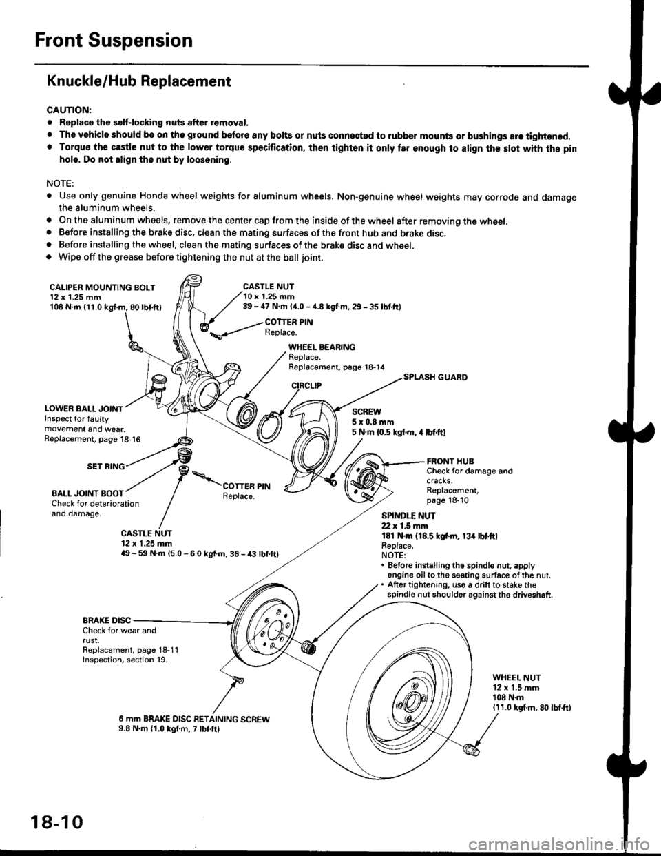
Knuckle/Hub Replacement
CAUTION:
. Replaco tho salf-locking nuts after romoval.
. The vehiclo should be on tho ground bsfore any bohs or nuls connected to rubber mounb or bushings are tightened.. Torqu€ th€ castle nut to the lowor torque specification, ihen tighton it only far enough to align th€ slot whh the pin
hole. Do not align the nut by loosening.
NOTE:
. Use only genuine Honda wheel weights for aluminum wheels. Non-genuine wheel weights may corrode and damagethe aluminum wheels.
. On the aluminum wheels, remove the center cap from the inside of the wheel after removing the wheel,. Before installing the brake disc, clean the mating surfaces of the front hub and brake disc,. Before installing the wheel, clean the mating surfaces of the brake disc and wheel.o Wipe off the grease before tightening the nut at the ball joint.
CALIPER MOUNTING BOLT12 x 1.25 mm108 N.m {11.0 kgl.m, 80lbf.ft)
LOWER BALL JOINTInspect for faultymovement and wear.
CASTLE NUT10 r 1.25 mm39 - ia7 N.m (4.0 - 4.8 kgf.m, 29 - 35 lbf,ftl
COTTER PINReplace.
WHEEL BEARINGReplace.Replacement, page 18-14
CIRCLIP
SCREW5x0.8mm5 N.m {0.5 ksl.m, 4 lbf.ftlReplacement, page 18-16
SET RING
BALL JOINT BOOT
FRONT HUBCheck for damage andcracks.Replacement,page 18-10Check for deteriorationand damage.
CASTLE NUT12 x 1.25 mm49 - 59 N.m l5.O - 6.0 kg{.m. 36 - /(} lbf,ftl
SPINDI.T ]{UT22 r 1.5 mmlEl N.m {18.5 kgf.rn, 13{ lbl.ttlReplace.NOTE:. Before instelling the spindle nut. apply6n9ine oilto th6 seating surface ofthe nut.. Atter tightening, uso a drift to stake thespindle nut should6r against the driveshaft.
BRAKE DISCCheck for wear andrust.Replacement, page 18-11lnspection, section 19.
WHEEL NUT12 x 1.5 mm'108 N.m1r1.0 kgf.m, 8lt lbf.ft)
6 mm BRAKE DISC RETAINING SCREW9.8 N.m 11.0 kgf.m, 7 lbtft)
18-10
Page 1176 of 2189
Master Cylinder/Brake Booster
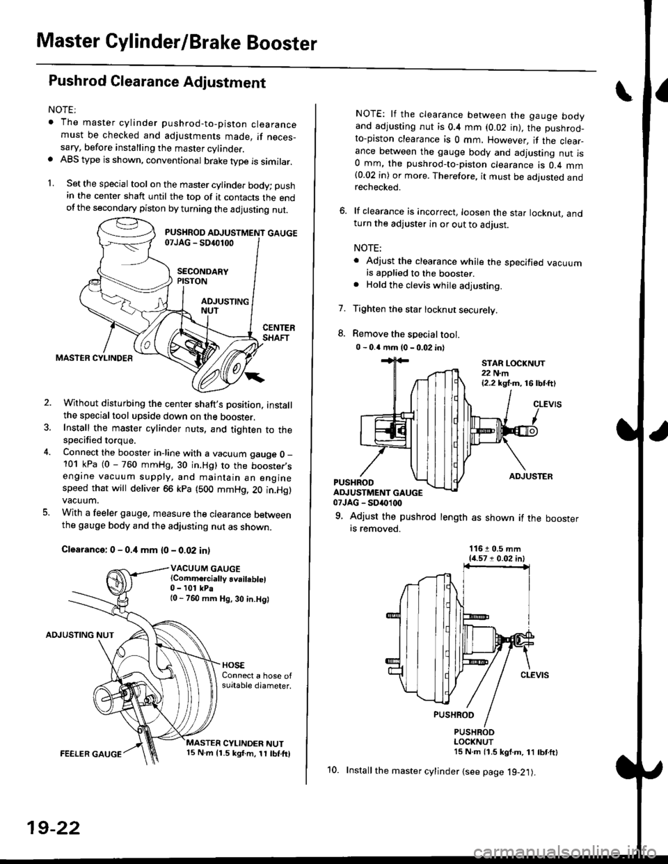
Pushrod Glearance Adjustment
NOTEr
. The master cylinder pushrod-to-piston clearancemust be checked and adjustments made, if neces_sary, before installing the master cylinder.. ABS type is shown, conventional brake type is similar.
1. Set the special tool on the master cylinde. body; push
in the center shaft until the top of it contacts the endofthe secondary piston by turning the adjusting nut.
Without disturbing the center shaft's Dosition, installthe specialtool upside down on the booster.Install the master cylinder nuts, and tighten to thespecified torque.
Connect the booster in-line with a vacuum gauge O _
101 kPa (0 - 760 mmHg, 30 in.Hg) to the booster,sengine vacuum supply, and maintain an enginespeed that will deliver 66 kpa (500 mmHg, 20 in.Hg)vacuum.
With a feeler gauge. measure the clearance Detweenthe gauge body and the adjusting nut as shown.
Clearance: 0 - 0.4 mm {0 - 0.02 in)
VACUUM GAUGE(Comm€rcially availeblel0 - 101 kPa{0 - 760 mm Hg, 30 in.Hg)
AOJUSTING NUT
FEELER GAUGE
19-22
10.
NOTE: lf the clearance between the gauge bodyand adjusting nut is 0.4 mm (0.02 in), the pushrod-to-piston clearance is 0 mm. However, if the clear_ance between the gauge body and adjusting nut is0 mm, the pushrod-to-piston clearance is 0.4 mm(0.02 in) or more. Therefore, it must be adjusted andrechecked.
6. lf clearance is incorrect, loosen the star locknut, andturn the adjuster in or out to adjust.
NOTE;
. Adjust the clearance while the specified vacuumis applied to the booster.. Hold the clevis while adjusting.
Tighten the star locknut securely.
Remove the special tool.
0 - 0.4 mm (0 - 0.02 in)
7.
ADJUSTERPUSHRODADJUSTMENT GAUGE07JAG - SD('1(x)
9. Adjust the pushrod length as shown if the boosterrs removed.
STAR LOCKNUT22 N.m{2.2 kg,f.m, 16lbtft)
11610.5 mm{{.571 0.02 in)
PUSHRODLOCKNUT15 N.m 11.5 kgf.m, 11 tbtftl
Install the master cylinder {see page l9-21).