1996 HONDA CIVIC ESP
[x] Cancel search: ESPPage 414 of 2189
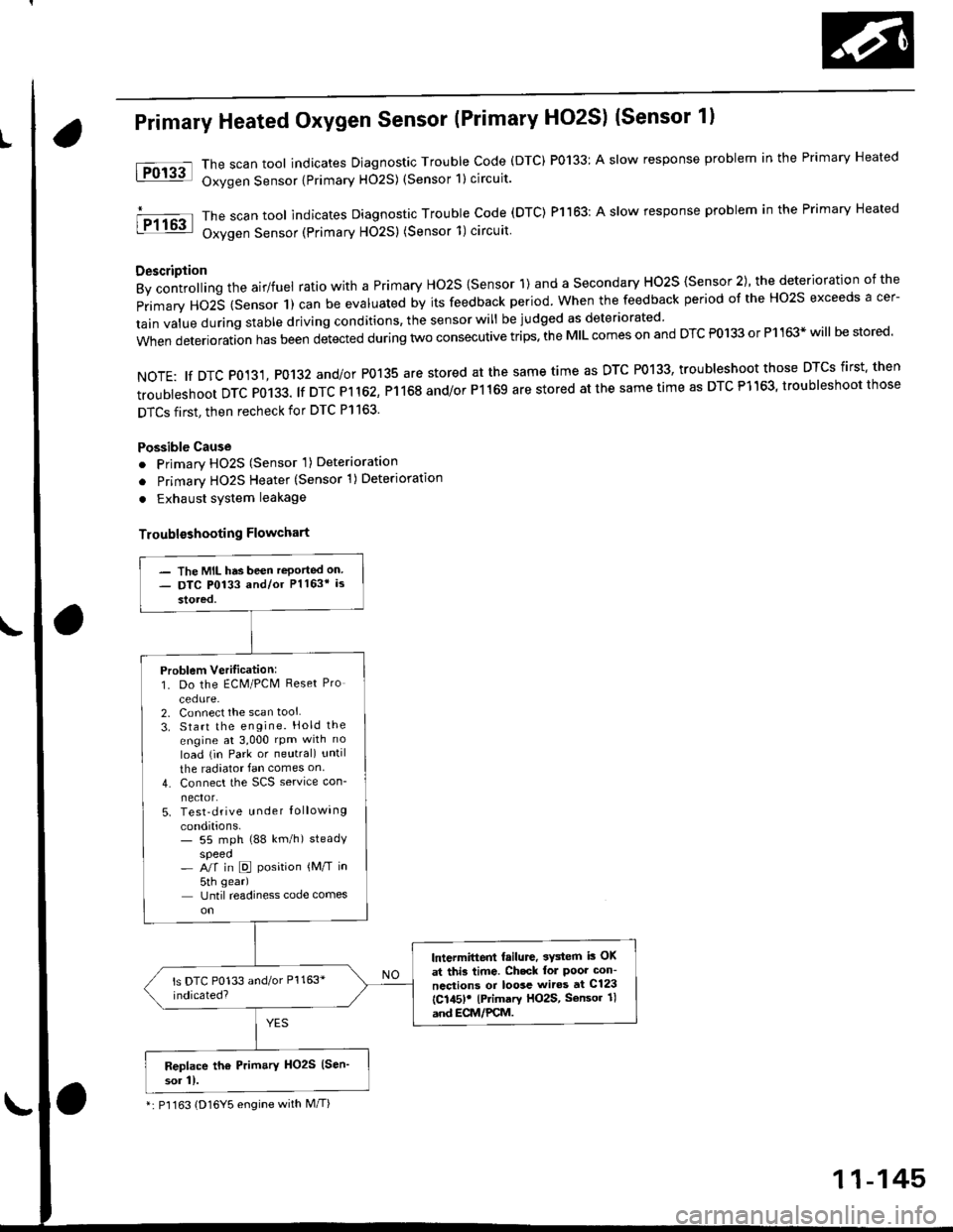
Primary Heated Oxygen Sensor (Primary HO2S) (Sensor 1l
The scan tool indicates Diagnostic Trouble Code (DTC) P0133: A slow response problem in the Primary Heated
Oxygen Sensor {Primary H02S) (Sensor 1) circuit.
The scan tool indicates Diagnostic Trouble code (DTC) Pl163: A slow response problem in the Primary Heated
Oxygen Sensor (Primary HO2S) (Sensor 1)circuit
Description
By controlling the airlfuel ratio with a Primary Ho2S {Sensor 1) and a secondary HO2S {Sensor 2), the deterioration of the
primary HO2S (Sensor 1) can be evaluated by its feedback period. when the feedback period of the Ho2s exceeds a cer-
tain value during stable driving conditions, the sensor will be judged as deteriorated
when deterioration has been detected during two consecutive trips. the MIL comes on and DTC P0133 or P1163* will be stored'
NOTE: tf DTC P0131, P0132 and/or P0135 are stored at the same time as DTC P0133, troubleshoot those DTCS first' then
troubleshoot DTC P0133. lf DTC Pl 162, P1168 and/or P1169 are stored at the same time as DTC P1163, troubleshoot those
DTCS first, then recheck for DTC Pl163.
Possible Cause
o Primary HO2S (Sensor 'l) Deterioration
o Primary HO2S Heater (Sensor 1)Deterioration
. Exhaust system leakage
Troublsshooting Flowchart
tFol3al
I P1163
- The MIL has been reported on- DTC P0133 and/or Pl163* is
stored,
Problem Verilication:1. Do the ECM/PCM Reset Pro
cedure-2. Connect the scan tool
3. Start the engine. Hold the
engine at 3,000 rpm with no
load (in Park or neutral) until
the radiator fan comes on
4. Connect the SCS service con-
nector.5. Test-drive u nder Iollowing
conditions.- 55 mph (88 km/h) steadyspeed- A/f in D position {M/T in
5th gear)
Until readiness code comes
lntermittent failure, 3Y3tem i3 OK
at thi3 time. Ch.ck lol Poor con-
ncctions or loosc wiros at C123
{C145)! lPrimary HO2S, Sensor 1l
and ECM/PCM.
Replace th6 Prim.ry HO2S (Sen'
sor 11.
*: P'l163 (D16Y5 engine with M/T)
11-145
Page 425 of 2189
![HONDA CIVIC 1996 6.G Workshop Manual PGM-FI System
Secondary Heated Oxygen Sensor (Secondary HO2S) {sensor 2l
[FO13a]l The scan tool indic€tes Diagnostic Trouble Code {DTC) P0139: A slow response probtem in the Secondary Heated- Uxygen HONDA CIVIC 1996 6.G Workshop Manual PGM-FI System
Secondary Heated Oxygen Sensor (Secondary HO2S) {sensor 2l
[FO13a]l The scan tool indic€tes Diagnostic Trouble Code {DTC) P0139: A slow response probtem in the Secondary Heated- Uxygen](/manual-img/13/6068/w960_6068-424.png)
PGM-FI System
Secondary Heated Oxygen Sensor (Secondary HO2S) {sensor 2l
[FO13a]l The scan tool indic€tes Diagnostic Trouble Code {DTC) P0139: A slow response probtem in the Secondary Heated- Uxygen Sensor (HOzS) (Sensor 2) circuit.
1 1-156
- The MIL has been reported on.- DTC P0139 is stored.
Problem verification:1. Do the ECM/PCM Reset Pro-
2. Start the engine. Hold theengine at 3,000 rpm with noload {in Park or neutral) untilthe radiator fan comes on.3. With the scan tool, check theSecondary HO2S (Sensor 2)output at 3,000 rpm.
Intermiftent failure, system i! OKat this tims. Check for pool con-nections or loos6 wiles at C131.{located undor ght lide of dash),C432' (locrted under middle otd.shl Cl25 (C782lr (SocondaryHO2S) (Sonsor 2) and ECM/FCM.
Does the voltage stay within0.3 - 0.6 V for two minutes?
*: D16Y8 engine
Page 434 of 2189
t
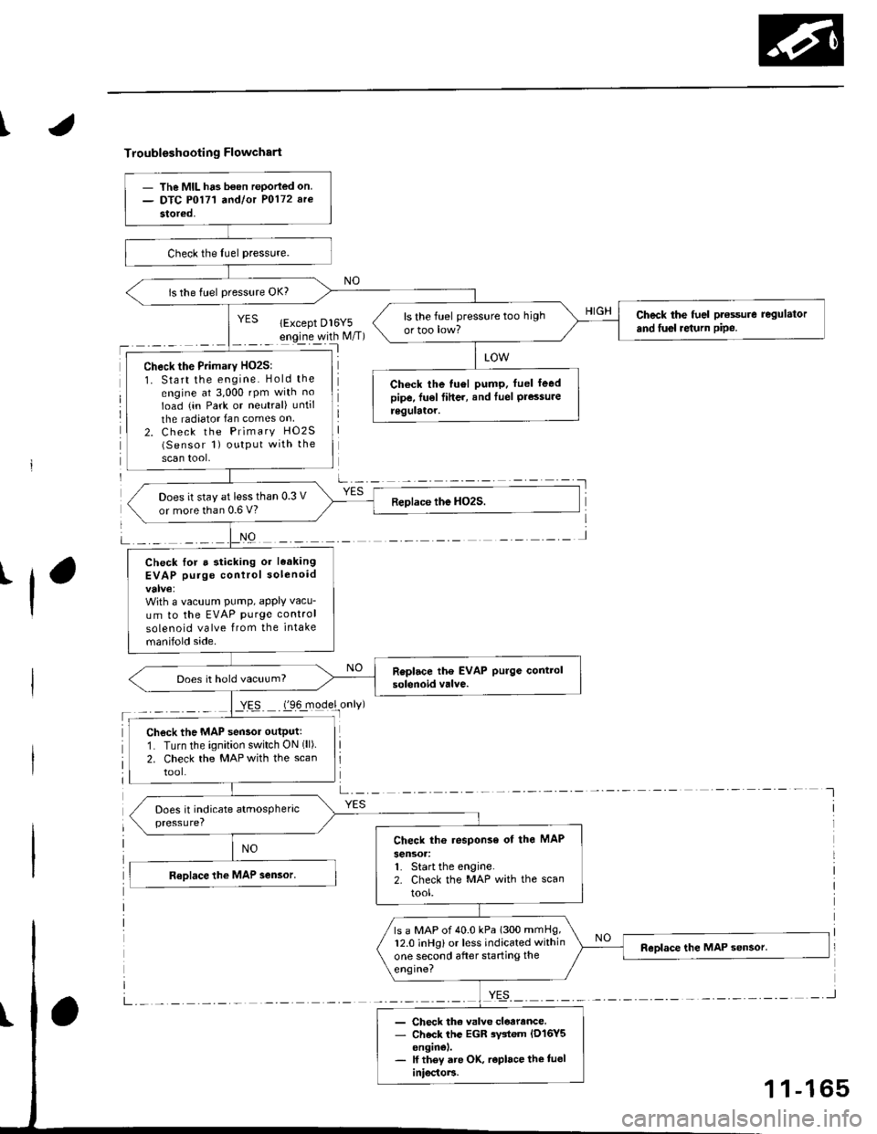
Troubleshooting Flowchart
'l
NO
a-,-:- -
YES
- The MIL ha3 b€on rePorled on.- DTC P0171 a^dlot P0172 arc
stored,
is the fuel pressure OK?
Check the fuel pt€ssure regulator
and fusl re{urn pipe.ls the fuel pressure too high
ortoo low?
Check the Primary HO2S:
1. Start the engine. Hold the
engine at 3,000 rpm with no
Ioad (in Park or neutral) until
the radiator Ian comes on
2. Check the Primary HO2S(Sensor 1) output with the
scan tool,
Check the tu6l pump. fuel leedpipe, fu€l fiher, and Iuel Pressureregulator.
Does it stay at less than 0.3 V
or more than 0.6 V?
Check lor a sticking or leaking
EVAP purge control solenoid
With a vacuum PumP, aPPIY vacu-
um to the EVAP purge control
solenoid valve from the intake
manifold side.
Does it hold vacuum?
Check the MAP sensor outputr
1. Turn the ignition switch ON (ll)
2. Check the MAP with the scan
tool.
Check th6 response of the MAP
sensoa:1. Start the engine.2. Check the MAP with the scan
tool.
ls a MAP of 40.0 kPa 1300 mmHg,12.0 inHg) or less indicated within
one second after starting the
engine?
- Check th€ valve cloarance.- Check the EGR rystem lD16Y5enginel.- lf they are OK, r€place the tueliniocto]3.
1 1-165
Page 435 of 2189
PGM-FI System
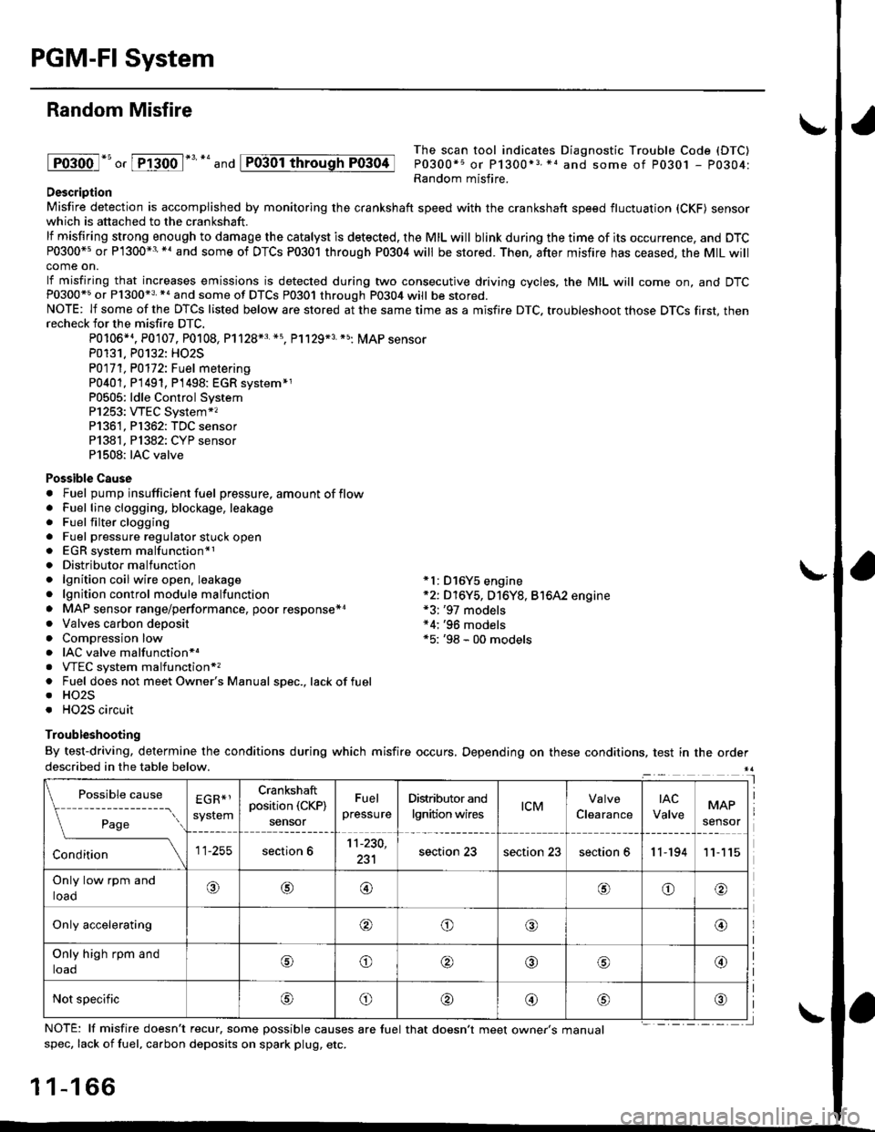
Random Misfire
lFoioo l*u o, [FTioo l*' *' and
The scan tool indicates Diagnostic Trouble Code (DTC)
P0300*5 or P1300*3 *1 and some of P0301 - P0304:Random misfire.Description
Misfire detection is accomplished by monitoring the crankshaft speed with the crankshaft speed fluctuation (CKF) sensorwhich is attached to the crankshaft.
lf misfiring strong enough to damage the catalyst is detected. the MIL will blink during the time of its occurrence, and DTCP0300*5 or P1300*3'*' and some of DTCs P0301 through P0304 will be stored. Then, after misfire has ceased, the MIL willcome on.
lf misfiring that increases emissions is detected during two consecutive driving cycles, the MIL will come on, and DTCP0300*5 or P1300*3 *a and some of DTCS P0301 through P0304 will be stored.NOTE: lf some of the DTCS listed below are stored at the same time as a misfire DTC. troubleshoot those DTCS first, thenrecheck for the misfire DTC.
P0106*4. P0107. P0108, P1128*3 *5, Pl129*3 *5; MAP sensorP0131. P0132: HO2S
P0171, P0112i Fuel metering
P0401, P 1491, P1498: EGR svstem*1P0505: ldle Control SystemP1253: VTEC System*,P1361, P1362: TDC sensorP1381, Pl382: CYP sensorP1508: IAC valve
Possible Cause. Fuel pump insufficient fuel pressure, amount of flow. Fuel line clogging, blockage, leakage. Fuel filter clogging. Fuel pressure regulator stuck open. EGR system malfunction*1. Distributormalfunction. lgnition coil wire open. leakage *l: D16Y5 engine. lgnition control module malfunction *2: D16Y5, D16Y8, Bt6A2 engine. MAP sensor range/performance, poor response*r *3: '97 models. Valves carbon deposit *4;'96 models. Compression low *5: '98 - 00 models. IAC valve malfunctionr.. VTEC system malfunction*,. Fuel does not meet Owner's Manual spec., lackoffuel. HO2S. HO2S circuit
Troubleshooting
By test-driving, determine the conditions during which misfire occurs, Depending on these conditions, test in the orderdescribed in the table below.
Possible
- --^ ---
rage
causeEGR*1
system
Crankshaft
position (CKP)
sensor
Fuel
pressure
Distributor and
lgnition wirestcMClearance
tAc
ValveMAP
sensor
section 611-230,
231section 23section 23section 611-19411
Only low rpm and
loado@@oo
Only accelerating@o@@
Only high rpm and
toaooo@
Not specificoo@
NOTE: lf misfire doesn't recur, some possible causes are fuel that doesn't meet owne/s manualspec, lack of fuel, carbon deposits on spark plug, etc.
1 1-1 66
I
P0304
Page 445 of 2189
PGM-FI System
Vehicle Speed Sensor (VSSI ('96 - 98 Models,'99 - 00 D16Y5 engine with M/Tl
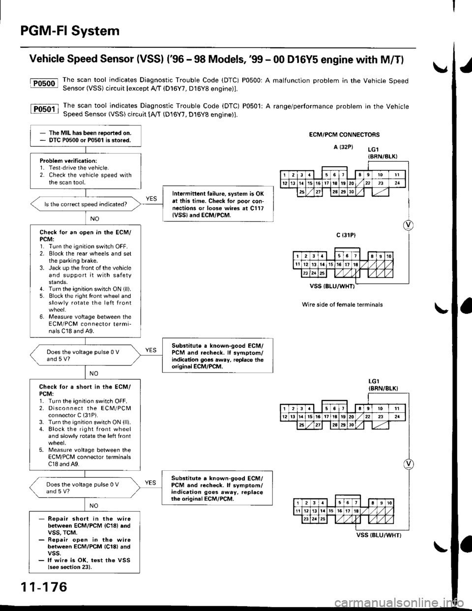
@The scan tool indicates Diagnostic Trouble Code (DTC) P0500: A malfunction problem in the Vehicle SpeedSensor (VSS) circuit Iexcept A!/T (D16Y7, D16Y8 engine)1.
The scan tool indicates Diagnostic Trouble Code (DTC) P0501: A range/performance problem in the VehicleSpeed Sensor (VSS) circuit [A,rT {D16Y7, D16Y8 engine)].
ECM/PCM CONNECTORS
A {32P} LG.t
VSS IBLU/WHT}
Wire side ot temale terminals
LGI(BRN/8LK}
The MIL has been reDorted on.DTC P0500 or P0501 is stored.
Problem verification:1- Test drive the vehicle.2. Check the vehicle speed withthe scan tool.
Intermittent tailure, system is OKat this time. Check tor Door con-nections or loose wires at C117{VSSland ECM/PCM.
ls the correct speed indicated?
Check for an open in the ECM/PCM:1. Turn the ignition switch OFF.2. Elock the rear wheels and setthe parking brake.3. Jack up the front of the vehicleand support it with safetystands.4. Turn the ignition switch ON (ll).
5. Block the right tront wheel andslowly rotate the left front
6, Measure voltage between theECM/PCM connector termi-nals C18 and A9.
Subslitute a known-good ECM/PCM and recheck. lf symptom/indic.tion goes away, replace theorisinal ECM/PCM.
Does the voltage pulse 0 Vand 5 V?
Check tor a short in ihe ECM/PCM:1. Turn the ignition switch OFF.2. Disco n n ect the ECM/PCMconnector C (31P).
3. Turn the ignition switch ON {ll).4. Block the right front wheeland slowly rotate the left front
5. Measure voltage between theECM/PCM connector terminalsC18 and A9.
Substitute a known-good ECM/PCM and recheck. lI symptom/indication goes away. replacethe original ECM/PCM.
Does the voltage pulse 0 Vand s V?
- Repair short in the wirebetwGen ECM/PCM {C18} endvss, TcM.- Repair open in the wirebetween ECM/PCM {Cl8} andvss.- lf wire is OK, test the VSSlsee section 23).
{BRN/BLK}
239l0lt
121611t8t9202321
2A2930
c {31P}
I38191o
tl12ialr5i6l10./
I2356a9l011
12l3l5t61tl8t920222a
27202930
12910
t2l13l.l7I l,/ 1,/231r.lslt., ),rlL
VSS {BLU/WHT}
11-176
Page 446 of 2189

fFosoo-l
lFosoil
Vehicle Speed Sensor (VSS) ('99 - 00 Models except Dl6Y5 engine with M/T)
Thescantoo|indicatesDiagnosticTroub|ecode(DTc)Po5o0:Ama|functionproblemintheVehic|espeed
Sensor (VSS) circuit lexcept A//T (D16Y/, D16Y8 engine)l'
Thescantoo|indicatesDiagnost|cTroub|eCode(DTC)Po5o1:Arange/performanceprob|emintheVehicle
SDeed Sensor {VSS) circuit tA,/T (D16Y7, D16Y8 engine)1.
ECM/PCM CONNECTORS
B {25P)
I
t
Wire side ol lemale terminals
ECM/PCM CONNECTORS
B E5PI
The MIL has been reported on
OTC P0500 or P0501 is stored.
Problem veritication:1. Test-drive the vehicle.
2. Check the vehicle speed with
the scan tool
lntermitt6nt failure, sYstem is OK
at thb time. Check tor Poor con-
nections or loose wir6 at C117
{vss} .nd ECM/PCM
ls the correct sPeed indicated?
Check for an open in the ECM/
PCM:1. Turn the ignition switch OFF.
2. Block the rear wheels and set
the parking brake
3. Jack uP the front ofthe vehicle
and support it with safety
stands.4. Turn the ignition switch ON (ll).
5. Block the right front wheel and
slowly rotate the left front
6, Measure voltage between the
ECM/PCM connector termi_
nals C23 and 820.
Substituto a known'good ECM/
PcM and rech€ck. ll sYmptom/
indic€tion goes awaY, lsplace the
original ECM/PCM.
Does the voltage Pulse 0 V
and 5 V or battery voltage?
Check for a short in the ECM/
PCM:1. Turn the ignition switch OFF.
2. Disco n n ect the EcM/PcM
connector C (31P).
3. Turn the ignition switch ON (ll)
4. Block the right front wheel
and slowly rotate the left front
5. Measure voltage between the
ECM/PCM connector terminals
C23 and 820.
Substiiute . known-good ECM/
PCM and r6check. lf symptom/indication goes awaY, rePlace
the origin.l ECM/PCM.
Does the voltage Pulse 0 V
and 5 V or battery voltage?
- Reoair short in the wire
between ECM/PCM {C23} and
vss. TcM.- Repai. open in the wire
between ECM/PCM {C231 andvss.- lf wire is OK, tesr the VSS
{see sestion 23).
Wire side oI female terminals
11-177
Page 459 of 2189

ldle Control System
System Description
The idle speed ot the engine is controlled by the ldle Air Control (lAC) Valve.The valve changes the amount of air bypassing into the intake manifold in response to electric current controlled bv theECM/PCM. When the IAC Valve is activated, the valve opens lo maintain the proper idle speed.
D16Y5, D16Y8, Br6A2 engine (M/T):
(ROTARYItac vat-vEEI{GINEcooLAI{T
VARIOUSsEI{SORS
VARIOUSSENSORS
INTAKE MANIFOTDDl6Ys {CVTl, D16Y8 engine lA/T):
D16Y7 engine:
{ROTABY)
;iy--, - ---
11-190
Page 460 of 2189
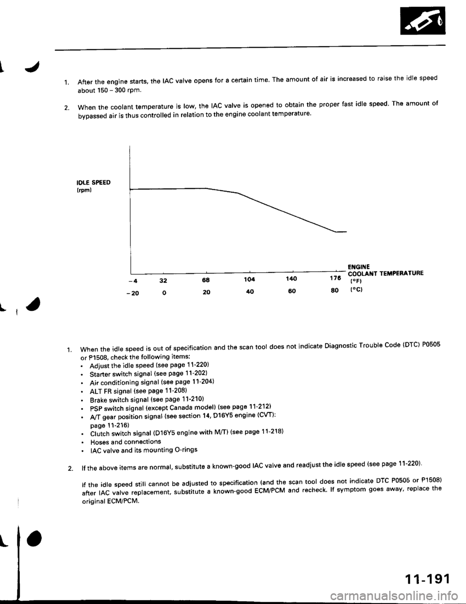
1.After the engine starts, the lAc valve opens for a certain time. The amount of air is increased to raise the idle speed
about 150 - 300 rpm.
When the coolant temperature is tow, the IAC valve is opened to obtain the proper fast idle speed. The amount of
bypassed air is thus controlled in relation to the engine coolant temperature'
IOLE SPEED
lrpml
176
80
ENGI ECOOLANI TEMPERATURE
t" Fl
toc)
ll
't.Whentheid|espeedisoutofspeciiicationandthescantoo|doesnotindicateDiagnosticTroub|ecode(DTc)P0505
or P1508. check the following items:
. Adiust the idle speed {see page 11-220}
. Starter switch signal (see page 11-202)
. Air conditioning signal (see page l1-204)
. ALT FR signal (see Page 11-2081
' Brake switch signal (see page 11-210)
. PSP switch signal (excapt Canada model) (see page 11-212)
. A,/T gear position signal {see section 14, Dl6Y5 engine (CVT):
page 11-216). Clutch switch signal (D16Y5 engine with M/T) (see page 11-218)
. Hoses and connections
' IAC valve and its mounting O-rings
lf the above items are normal, substitute a known-good IAC valve and readjust the idle speed (see page 11-220)
|ftheid|espeedsti||cannotbeadjustedtospecification(andthescantoo|doesnotindicateDTcP0505orP]50S)
after IAC valve replacement. substitute a known-good ECM/PCM and recheck. lf symptom goes away, replace the
original ECM/PCM.