Page 1708 of 2189
Moonroof
1.
Switch Test
Carefully remove the switch from the driver's dash-
board lower cover {see page 23-205}.
Check for continuitv between the terminals in each
switch position according to the table.
Terminal
t*',*-----__\I234
ut-t-
OPENo--o
CLOSEo---o
TILTo--o
23-234
Motor Test
'1.Remove the headliner (see section 20).
Disconnect the 2P connector from the moonroof
motor.
Terminal side of male terminals
Check the motor by connecting power and ground
according to the table.
4. lf the motor does not run, replace it (see section 20).
NOTE: See Closing Force Check in section 20 for
motor clutch test.
\_____lTr1
Position
,l
OPENo@
CLOSE@
Page 1709 of 2189
Open/Close-Tilt/Close Switch Test
1. Remove the headliner (see section 20).
2. Disconnect the 2P and 4P connectors from the moon-
roof motor and the switch.
3. Check for continuity between the terminals in each
switch position according to the table.
Terminal side of male terminals
Terminal
*r*"-
-\123
CLOSE .* TILTo--oo---o
CLOSE ..--. OPENo--o
4. lf there is no continuity, adiust or replace the switch'
l-t
23-239
Page 1714 of 2189

Cruise Gontrol
3.
1.
2.
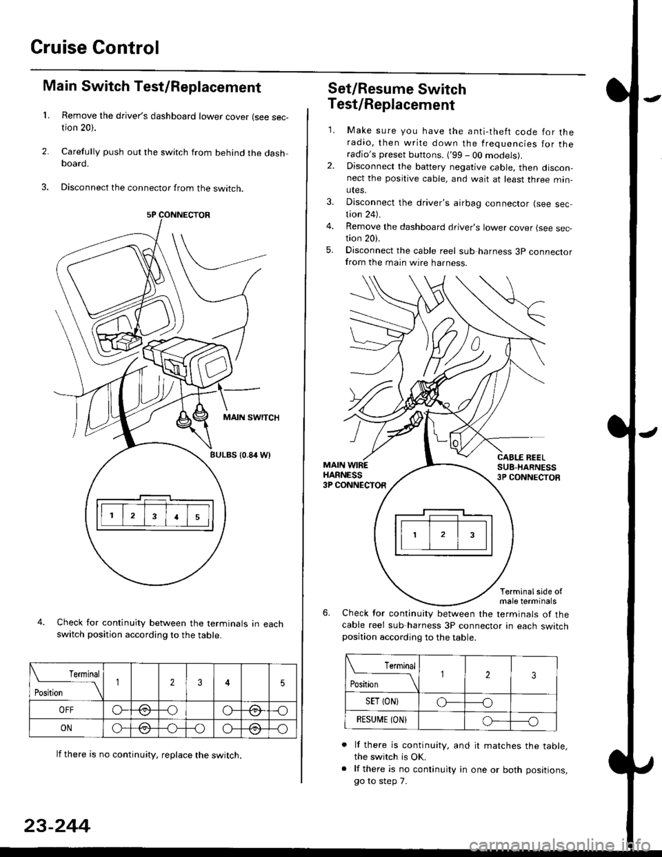
Main Switch Test/Replacement
Remove the driver's dashboard lower cover (see sec-tion 20).
Carefully push out the switch from behind the dashboard.
Disconnect the connector from the swtrcn.
MAIN SWITCH
BULBS {0.84 Wt
Check for continuity between the terminals in eachswitch position according to the table.
lf there is no continuity. reDlace the switch.
4.
Terminal
r**
--\235
OFFo--oGa\-o\:./\a/
ONo-/a-oo--o\:/\:/
23-244
Set/Resume Switch
5.
Test/Replacement
2.
1.
MAIN WIREHARNESS3P CONNECTOR
Make sure you have the anti-theft code for theradio, then write down the frequencies for theradio's preset buttons. ('99 - 00 models).Disconnect the battery negative cable, then discon-nect the positive cable, and wait at least three min-utes.
Disconnect the driver's airbag connector (see sec-tion 24).
Remove the dashboard driver's lower cover (see sec,tion 20).
Disconnect the cable reel sub harness 3p connectorfrom the main wire harness.
CABLE BEELSUB-HARNESS3P CONNECTOS
Terminalside ofmale terminals
Check for continuity between the terminals of thecable reel sub-harness 3P connector in each switchposition according to the table.
L Terminal
Position123
SET (ON}o----o
BESUi,|E IONIo-----o
lf there is continuity, and it matches the table,the switch is OK.
lf there is no continuity in one or both positions,
go to step 7.
Page 1715 of 2189
7. Remove th€ two screws, then remove the switch'
Check for continuity between the terminals in switch
position according to the table.
Terminal
t"-"t*
-\23
SET (ON)o--o
RESUI\4E {ON}o----o
lf there is continuity, and it matches the table,
replace the cable reel.
lf there is no continuity in one or both positions,
reDlace the switch.
8.
SET/NESUME
l-l
23-245
11.
q
10.
12.
lf all tests prove OK, reconnect the cable reel and
cable reel sub-harness connector, then reinstall the
steering column covers
Reconnect the driver's airbag connector. and rein-
stall the access panel on the steering wheel.
Reconnect the battery positive cable, then the nega-
tive cable.
After connecting the airbag connectors, confirm
proper system operation; Turn the ignition switch ON
(ll); the SRS indicator light should come on for about
six seconds and then go off.
Enter the anti-theft code for the radio, then enter the
customer's radio station presels {'99 -00 models)'
Page 1716 of 2189
Cruise Control
Brake Switch Test
1. Disconnect the 4P connector from the switch.
4P CONNECTOR
BRAKEPEDAL
Check for continuity between the terminals accord-
ing to the table.
Terminal
t"r. ** \
123
RELEASEDo---o
DEPRESSEDoo
3. lf necessary. replace the switch or adjust pedal
height (see sectionl9).
23-246
clutch switch Test (M/Tl
1. Disconnect the 2P connector from the switch.
swtTcH
2. Check for continuity between the terminals accord-
ing to the table.
Terminal
.***aal
-\I2
RELEASED
DEPRESSEDo--o
3. lf necessary, replace the switch or adiust pedal
height (see section '12).
Page 1719 of 2189
)Actuator Solenoid Test
1. Disconnect the 4P connector from the actuator'
ACTUATOR
2. Check for resistance between the terminals accord-
ing to the table.
NOTE: Resistance will vary slightly with tempera-
ture; sDecified resistance is at 70"F (20'C).
SAFETY VALVE
VACUUMVALVE
J
From VENTHOSE
+ To VACUUM
Terminalside otmale terminals
Terminal
Resistance (O) \
234
VENT SOLENOID40 600o---o
VACUUM SOLENOID30- 500G---o
SAFETY SOLENOID40- 600o---o
l)
TANK
23-249
Page 1734 of 2189
Power Door Locks
Audio Unit lKeyless Receiver
Circuitl Terminals ('96 - 98 modelsl
CavityWireDestination
16P CONNECTOR
B1BLU/REDlgnition key switch
*82LT GRNTrunk latch switch
Ft2BLU/YELUnlock (Driver's door)
B4BLUValet switch
*85LT BLUSecurity {lN)
B6BLK/YE LNo. 14 (7.5 A) fuse
*81ORNSecurity (D2)
B8LT GRN/BLKCeiling light
B9GRN/ORNUnlock (All doors)
810GRNA/VHTLock (OutPutl
*811BLU/WHTLED O
*812WHT/BLKSecurity (D0)
+B 13YEL/BLUSecurity (D'l )
814LT GRN/REDDoor switch
B15BLKG round (G401, G402)
o toGRYnorn
*: For security system (option)
23-264
Driver's Door Lock Switch Test
1. Remove the inner handle (see section 20).
2. Disconnect the 3P connector from the door lock
switch.
Check for continuity between the terminals in each
switch position according to the table.
DRIVER'SDOORLOCKswtTcH
Terminal
Position123
LOCKo-----o
OFF
UNLOCKo----o
Page 1735 of 2189

l
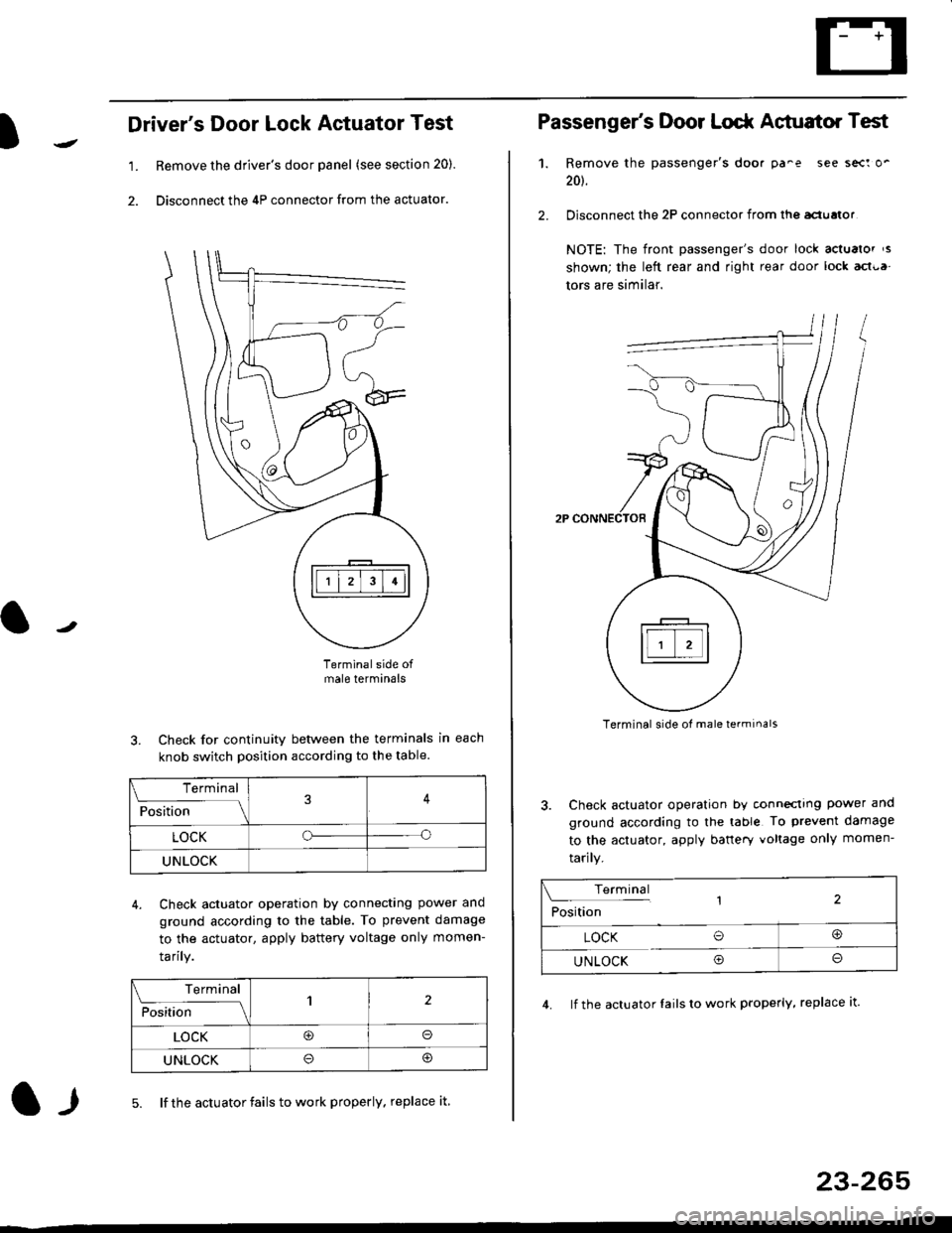
Driver's Door Lock Actuator Test
1. Remove the driver's door panel (see section 20).
2. Disconnect the 4P connector from the actuator.
J
Terminalside ofmale terminals
3. Check for continuity between the terminals in each
knob switch position according to the table.
4. Check actuator operation by connectlng power ano
ground according lo the table. To prevent damage
to the actuator, apply battery voltage only momen-
tarilY.
l-l5. lf the actuator fails to work properly. replace it
23-265
Terminal
F""lti* - lll
LOCKo
UNLOCK
Terminal
Fo"JJ'-lrlon';" -ll1
LOCK@o
UNLOCK
Passenger's Door Lodr Actuator Test
1.
2.
Remove the passenger's doo. pa^e see sect o'
201.
Disconnect the 2P connector from lhq aclualor
NOTE: The front passenger's door lock actualor ,s
shown; the left rear and right rear door lock act{,a
tors are similar.
Terminal side ol male terminals
3. Check actuator operation by conneclrng power and
ground according to the table To prevent damage
to the actuator, apply banery voltage only momen-
tarily.
4. lf the actuator Iails to work properly, replace it.
Terminal,2Position
LOCK O@
UNLOCK Oo