Page 1635 of 2189

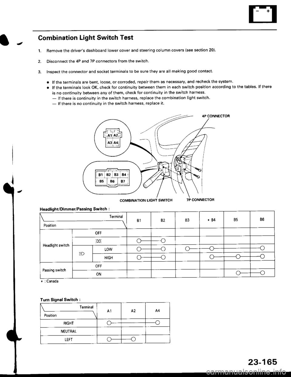
Combination Light Switch Test
1.Remove the driver's dashboard lower cover and steering column covers (see section 20)
Disconnect the 4P and 7P connectors from the switch.
Inspect the connector and socket terminals to be sure they are all making good contact
. lf the terminals are bent, loose. or corroded, repair them as necessary, and recheck the system.
. lf theterminals look OK, check for continuity between them ineach switch position according tothetables lfthere
is no continuity between any of them. check for continuity in the switch harness
- lf there is continuity in the switch harness. replace the combination light switch
- lf there is no continuity in the switch harness, replace it.
2.
4P CONNECTOR
COMBINATION LIGHT SWITCH7P CONNECTOR
HsadlighUDimmer/Passing Switch :
* : Canada
rrr r-l
l(rr mf ItffiTI A3 A11l
Terminal
Position
B182B3*84B586
Headlight switch
OFF
o---o
LOWo---oo-----o
HIGHo-----oo---o
Passing switchOFF
ONo-----o
Turn Signal Switch :
Teminal
;',*;----__\A1A2A4
RIGHToo
NEUTRAL
LEFToo
23-165
Page 1638 of 2189

Headlights
Adjustment
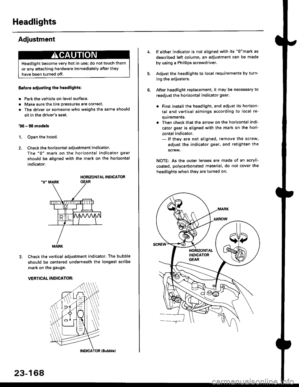
Eoforo adiu3ting th€ h.adlights:
. Park the vehicle on level surface.
. Make sure the tire prgssures are correct.
a The driver or someone who weighs the same should
sit in the driver's seat.
96 - 98 modols
1. Open the hood.
2. Check the horizontal adjustment indicator.
The "0" mark on the horizontal indicator gear
should be aligned with the mark on the horizontal
indicator.
HORIZONTAL INDICATOR
Check the vertical adjustment indicator. The bubble
should be centered underneath the longest scribe
mark on the gauge.
VERTICAL INDICATOR:
Headlight become very hot in use; do not touch them
or any attaching hardware immediately after they
have been turnsd off.
MARK
23-164
(Bubblol
lf either indicator is not aligned with its "0"mark as
described left column, an adjustment can be made
by using a Phillips screwdriver.
Adjust the headlights to local requirements by turn-
ing the adjusters.
After headlight replacement, it may bs necessary to
readjust the horizontal indicator gear.
. First install the headlioht, and adjust its horizon-
tal and vertical aimings according to local re-
quirements.
. Then check that the arrow on the horizontal indi-
cator gear is aligned with the mark on the hori-
zontal indicator.- lf they are not aligned, remove the screw,
adiust the indicator gear, and retighten the
screw.
NOTE: As the outer lenses are made ot an acryli-
coated, polycarbonated material, do not cover the
headlights when they are turned on.
Page 1640 of 2189

Headlights
Adjustment (cont'dl
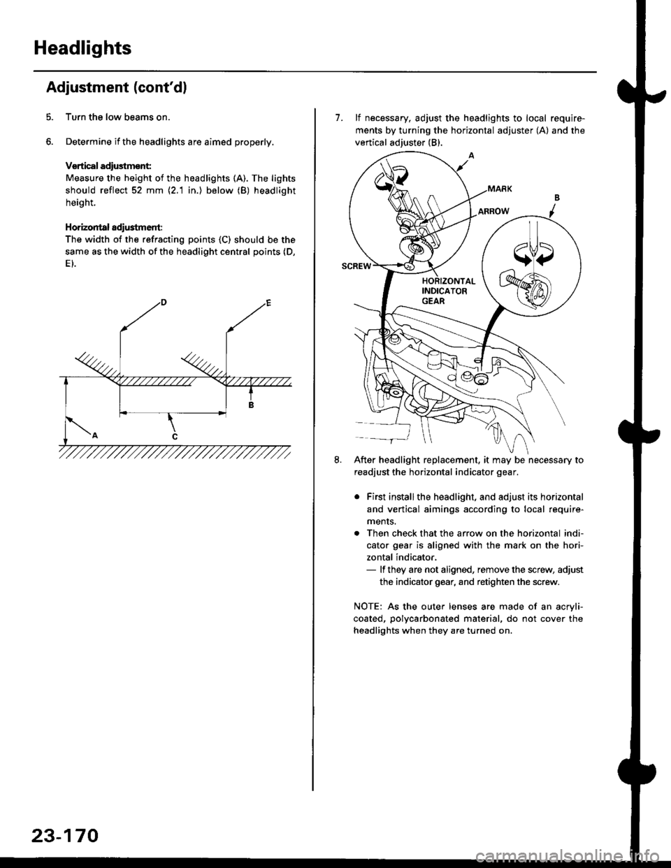
Turn the low beams on.
Determine if the headlights are aimed properly.
Vsrtical adiustmsnt:
Measure the height of the headlights (A). The lights
should reflect 52 mm \2.1 in.) below (B) headlight
height.
Horizontal adi$tment:
The width of the refracting points (C) should be the
same as the width of the headlight central points (D,
23-170
7. lf necessary, adjust the headlights to local require-
ments by turning the horizontal adjuster (A) and the
vertical adjuster (B).
After headlight replacement, it may be necessary to
readjust the horizontal indicator gear.
. First installthe headlight, and adjust its horizontal
and vertical aimings according to local require-
ments.
. Then check that the arrow on the horizontal indi-
cator gear is aligned with the mark on the hori-
zontal indicator,- lf they are not aligned, remove the screw, adjust
the indicator gear, and retighten the screw.
NOTE: As the outer lenses are made of an acryli-
coated, polycarbonated material, do not cover the
headlights when they are turned on.
Page 1645 of 2189
Hazard Warning Switch Test
CAUTION: Be careful not to damage the hazard warn-
ing switch or the center outlet panel when prying the
switch out.
'96 - 98 models:
'1. Pry the hazard warning switch out of the center out-
let panel.
2. Disconnect the 'l0P connector from the hazard warn-
ing switch.
3. Check for continuity between the terminals in each
switch position according to the table
HAZARDWARNINGlOP CONNECTOR
q-
Check for continuity between the terminals in
switch position according to the table.
Terminal No,4 is not used.
Terminal
t** \
12356I9l0
OFFoo
ot !.1o
ONo-ooo
o.o
o@o
'99 - 00 models:
1. Remove the center panel lsee section 20).
2. Remove the two screws, then remove the switch
from the center Panel
scREwsHAZARDWARNINGswlTcH
CENTER PANEL
.
Page 1655 of 2189
Ceiling Light Test
1. Turn the light switch OFF
2. Pry off the lens.
3. Remove the two mounting nuts (or a bolt) from the
housing, then remove the housing.
4. Disconnect the connector{s) from the housing.
5. Check for continuity between the terminals in each
switch position according to the table.
With moonroof:
3P CONNECTOR
rermrnal
Position \
12or2'
3or3'�
OFFo-/a\-o\7
MIDDLEo-,.\--o\:/
ONo---o\:/
23-185
q,
Without moonroot:
Coupe/Hatchback:
BULB (5 WI
/
2'
4
1
3
Page 1656 of 2189
Interior Lights
Spotlights Test
1. Turn the spotlight switch OFF.
2. Pry off the lens.
3. Remove the two screws and the housing.
4. Disconnect the 1P connector from the housing.
5. Check for continuity between the terminals in each
switch position according to the table.
Terminal
t*'*-__\234
OFFo-{e,
//:\
--o
--o\:,/
ONo--*i@
/a\
-_o
--o\:.,/
23-186
Trunk Light Test
1. Open the trunk light cover from the housing.
2. Pry out the light assembly.
3. Disconnect the 2P connector from the housing,
4. Make sure that the bulb is OK. Check for continuitybetween the No. 1 (+) and No.2 (-) terminals.
EULB {.')
*1 3.4 W: USA, Canada-oroduced5 W: Japan-produced
Page 1681 of 2189
I
r Switch Test
Without detogg€r:
1. Remove the switch as dsscribed in Function Test
(see page 23-207).
2. Check for continuity betw€en the terminals in each
switch position according to the table.
Mirror Switch:
POWER MIRROB
swlTcH
Terminal
rL*"--_\
23456n9
L
UP-o
o-
DOWNo--oo--o
LEFTo-o--o
RIGHTo--o
o--o
UPo--o
o--o
DOWNo--oo--o
LEFIo--oo--o
RIGHT-o
o--o
l-
23-211
1. Prv the switch out of the dashboard driver's lower
With defogger:
POWER MIRRORswtTcH
Disconnect the 1OP connector from the switch'
Check for continuity between the terminals in each
switch position according to the table
Mirror Switch:
Terminal
Position \l2789't0
L
UPo-o-
-o-o
DOWNo-o--o-a
o-
o-
-o--o
RIGHTo--o
o--O
UPGo-
-o-o
DOWNo--o
G--o
LEFTo--o-oo-
RIGHT
-o
o--o
Dofogger Swhch:
Terminal
Posilion \
2
ONo-/l>\-osv
OFFo---o
Page 1682 of 2189
Power Mirrors
Power Mirror Test
1. Pry out the cover panel (see section 20).
Terminalside ofmale terminals
*: Canada '99 - 00 models
Disconnect the 8P connector from the power mirror.
Check actuator operation by connecting power and
ground according to the tables.
Dofogger Test:
4. Check for continuity between the No. 3 and No. 4
terminals of the 8P connector.
There should be continuity.
COVER
L___r"'ry1Position67I
TILT UPo@
TILT DOWN@
SWING LEFTo@
SWING RIGHT@
23-212
Mirror Actuator Replacement
(Donnelly Typel
'1. Remove the power mirror from the door {see sec-
tion 20). and disconnect the 8P connector.
2. Remove the mirror base cover from the mirror
housing.
MIRROR HOLDER
Remove the mirror holder from the mirror housing.
Gently pull it out by hand.
Remove the three screws from the actuator and the
two screws from the bracket at the base of the
assemory.
BRACKET
5. Remove the bracket from the housinq.
4.
MIRROR HOUSING