Page 1598 of 2189
Gauge Assembly
Component Location Index
SRS components are located in this area. Review the SRS component locations, precautions, and procedures in the SRS
section (24) before performing repairs or service.
6x1.0mm9.8 N.m 11.0 kgf.m,22lbt.lrl
VEHICLE SPEED SENSOR {VSS)Troubleshooting, page 23-1 40
GAUGE ASSEMBLYGau ge/lndicator/TerminalLocation Index, page 23-129Removal, page 23-135Bulb Location, page 23-136Disassembly, page 23 138
PARKING BRAKE SWITCH
FLUIO LEVEL SW]TCH
23-128
ENGINE OIL PR€SSURE SWITCH
Page 1599 of 2189
JGau ge/lndicator/Terminal
With tachometer;
CONNECTOR "A"
{A/T GEAR POSITION INDICATOR}
Location lndex
CONNECTOR "8"
{GAUGE and INOICATOR)CONNECTOB "C"
CONNECTOR "D"
{ABS INDICATORI
SPEEDOMETER:Indicates 60 km/h at 637 rpm or
60 mph at 1,025 rpm o{thevehicle speed sensor (VSS).
A/T GEAR POSITIONINDICATORSee page 23 149
TACHOMETER:Indicates 100 rpm at200 pulses per minuteol the ignition controlmodule (lCMi.FUEL GAUGEENGINE COOLANT TEMPERATURE (ECT) GAUGE
(cont'd)
23-129
(GAUGE end INDICATORI
A1-----------+816
JlltlllulllllrL
c1 --------->c13
1ililil{ilrL
oooo o 0006^
)og @ @ o^o @ )'l |. o
Fl- - -> F5E1_ _ -->E5D1- --+05
oo/ \oo
Gauge/Sending Unit Test, page 23-142
Page 1600 of 2189
Gauge Assembly
Gauge/lndicator/Terminal Location Index (cont'd)
Without tachometer:
CONNECTOR "A"
IA/T GEAR POSITION INDICATORICONNECTOR "8"
{GAUGE and INDICATOR}CONNECTOR "C"
(GAUGE and INDICAIORI
CONNECTOR "F"
{SRS INDICATOR)CONNECTOR "D"
{ABS INDICATORI
SPEEDOMETER:Indicates 60 km/h at 637 rpm or60 mph at 1,025 rpm ofthevehicle speed sensor (VSS).
ENGINE COOLANT TEMPERATUFE (ECT) GAUGEA/T GEAR POSITIONINDICATOFSee page 23 149FUEL
A1 ------> 46
----> al4
B1. - --------------->B16
JilililHililil1
C1-- - --------..+C13
JililHililL
Oo_o-o O 0006
lus 0 0 Bu-. )
oo/ \oo
23-130
Gauge/Sending Unit Test, page 23 142
Page 1602 of 2189
Gauge Assembly
(Wnh lachomolgr)
I cNfldt--]I CONTRoL II MODULE
I 0cM) :
tvl
i.ll
|
-i;,
i
TURN SIGNAUHAZAROWARNINGswtTcH
Circuit Diagram {cont'd)
Fh"lurous @)- BLrcwHT + BLKryEL
fi'Sfvrous 16r.- veLPAGE
RIGHT
V
IGR&ryE
LEFT
V
I
No.s (104)FUSE
V
IBEO/GRN
lru
8LU4RE0
ABSCONTROLUNIT
-rl
eLui'rvrr
G401G402G401G442
23-132
Page 1608 of 2189
Gauge Assembly
Disassembly (With Tachometerl
NOTE: Handle the terminals and Drinted circuit boards
carefully to avoid damaging them.
A/T GEAR POSITION INDICAMOUNNNG SCREWStx 2)
FUEL and ENGINE COOLANT TEMPEMTUREGAUGE MOUNTING SCREWS {x 6,TACHOMETEB MOUNTINGSCREWS lx 3l
ao
,-ook+r
.,- ll $
t'{"{q.' ElI ..il \:r
A/T GEAR POSITION INOICAPRINTED CIRCUIT BOARD
INDICATORPRINTED CIRCUIT BOARD
@ FUEL end ENGINE COOLANT TEMPERATURE (ECTI
PRINTEO CIRCUIT
q,
6\
ABSCRUISE or SHIFT-UP INDICATORPRINTED CIRCUTT EOARD
TACHOMETERSpecilication, page 23 129
METER PANEL
booo .--:o'-..oooo.A
:-F.-sr'; "€?;"')
aFl l!
GAUGE
23-134
Page 1609 of 2189
JDisassembly {Without Tachometerl
NOTE: Handle the terminals and printed circuit boards
carefully to avoid damaging them.
SPEEDOMETER MOUNTINGSCREWS (x 4)
A/T GEAR POSITION INDICAMOUNTING SCREWS {x 2l
SRS INOICATORPRINTED CIRCUIT BOARD
ENGINE COOLANT TEMPERATURE {ECT}
GAUGE
ABS INDICATORPRINTED CIRCUIT BOARD
PRINTED CIRCUIT
METER PANEL
FUEL GAUGEMOUNTING SCREWS {x 3)ENGINE COOLANT TEMPERATUR€GAUGE MOUNTING SCREWS {x 3l
A/T GEAR POSITION INDICATOR
PRINTED CIRCUIT BOARD
'a@
.-@--o
o"i^>
Er t
lmwp\
d*re
\*P
\
FUELTest,GAUGEpage 23-142
oOo ,.-'€'-., oOOo -/\
€3,'" ' "$?'----"')
)a.' '.,,'+ ':j
\ll Lto
BOARD
METER LENSMETER VISOR
23-139
Page 1610 of 2189
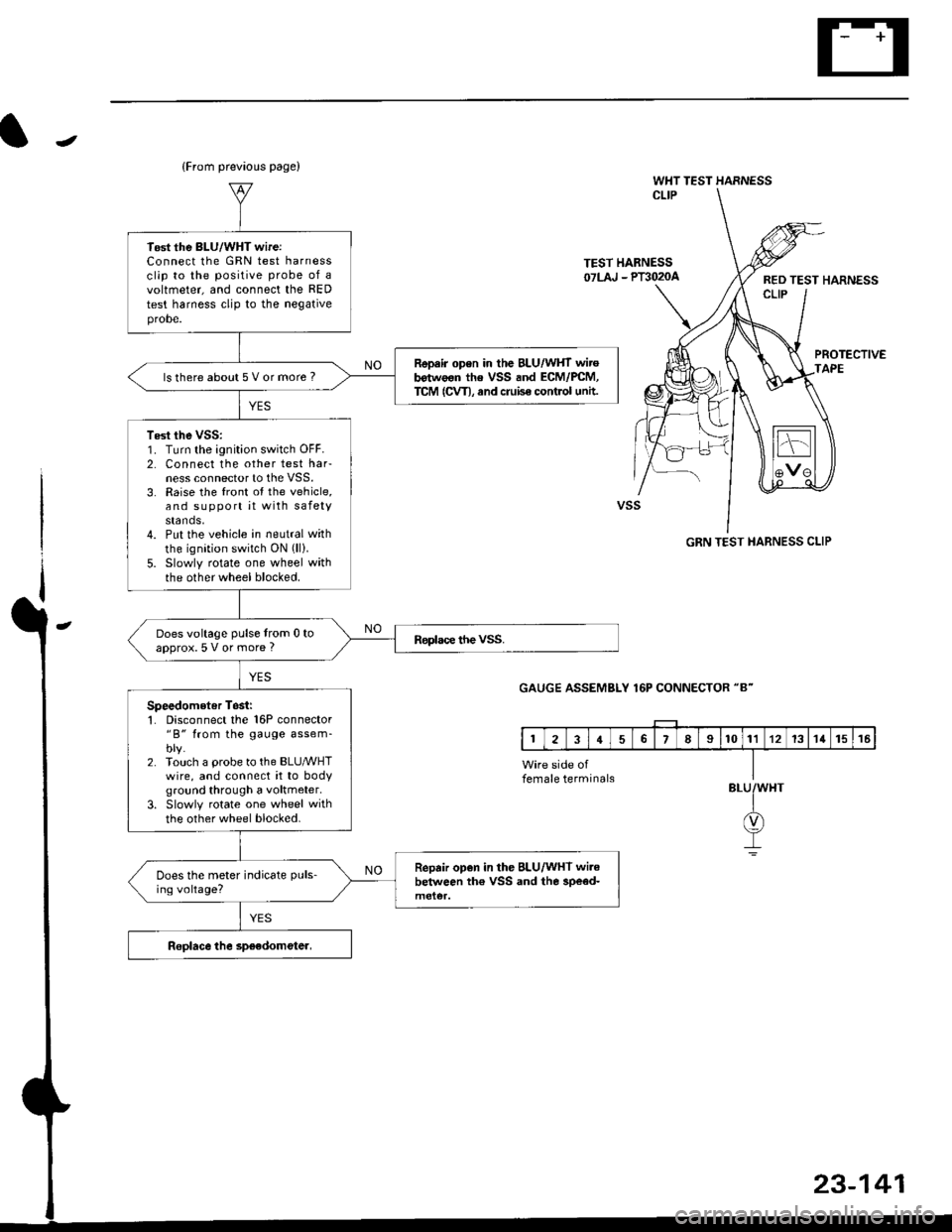
Vehicle Speed Sensor (VSSI
Troubleshooting
Before testing, inspect the No. 15 (7.5 A) fuse in the under-dash fuse/relay box.
TEST HARNESSOTLAJ _ PT3O2OAREO TEST HARNESSCLIP
PROTECTIVETAPE
TEST HARNESSOTLA' . PT3O2OA
(To next page)
Test the BLK wire:1. Disconnect the 3P connectorfrom the vehicle speed sensor(vss).
2. Connect the test harness(07LAJ PT30200) only to theengine wire harness,3. Connect the RED test harnessclip to the positive probe of a
4. Check for continuity betweenthe RED test harness clip andbody ground.
Repair opon in the BLK wireb€twe€n the VSS and G101.ls there continuity?
Te3t the BLK/YEL wire:1. Connect the WHT test harnessclip to the positive probe of avoltmeter, and connectthe REDtest harness clip to the negativeprobe.2. Turn the ignition switch ON {ll).
Repair open in iho BLK/YEL wirebetween the VSS and the under-d6sh tuse/relav box.
vss
GRN TEST HARNESS
RED TEST HARNESS
WHT TEST HARNESS CLIP
23-140
Page 1611 of 2189

J
(From prevaous page)
WHT TEST HARNESSCLIP
TEST HABNESS07LAJ - Plil020aRED TEST HARNESSCLIP
PROTECTIVEAPE
GRN TEST HARNESS CLIP
GAUGE ASSEMBLY 16P CONNECTOR "8"
BLU
23-141
Tost the BLU/WHT wireiConnect lhe GRN test harnessclip to the positive probe of avoltmeter, and connect the RED
test harness clip to the negativeprobe.
Repair open in the BLU/WHT wirob€twoon the VSS and ECM/PCM,TCM (CVT), and cruise control untt.ls there about 5 V or more ?
Test the vss:1. Turn the ignition switch OFF.2. Connect the other test harness connector to the VSS.3. Raise the front ot the vehicle,and support it with safetystands,4. Put the vehicle in neutral with
the ignition switch ON (ll).
5. Slowly rotate one wheel withthe other wheel blocked.
Does voltage pulse from 0 toapprox.5 V or more ?
Speedometer Tosii'1. Disconnect the 16P connector"B" from the gauge assem-blv.2. Touch a probe to the BLUMHTwire, and connect it to bodyground through a voltmeter.
3. Slowly rotate one wheel with
the other wheel blocked.
Repair open in the BLU/WHT wi.ebelween th€ VSS and the 3pe€d-Does the meter indicate puls-
ing voltage?
female terminals