Page 1681 of 2189
I
r Switch Test
Without detogg€r:
1. Remove the switch as dsscribed in Function Test
(see page 23-207).
2. Check for continuity betw€en the terminals in each
switch position according to the table.
Mirror Switch:
POWER MIRROB
swlTcH
Terminal
rL*"--_\
23456n9
L
UP-o
o-
DOWNo--oo--o
LEFTo-o--o
RIGHTo--o
o--o
UPo--o
o--o
DOWNo--oo--o
LEFIo--oo--o
RIGHT-o
o--o
l-
23-211
1. Prv the switch out of the dashboard driver's lower
With defogger:
POWER MIRRORswtTcH
Disconnect the 1OP connector from the switch'
Check for continuity between the terminals in each
switch position according to the table
Mirror Switch:
Terminal
Position \l2789't0
L
UPo-o-
-o-o
DOWNo-o--o-a
o-
o-
-o--o
RIGHTo--o
o--O
UPGo-
-o-o
DOWNo--o
G--o
LEFTo--o-oo-
RIGHT
-o
o--o
Dofogger Swhch:
Terminal
Posilion \
2
ONo-/l>\-osv
OFFo---o
Page 1684 of 2189
Wipers/Washers
Component Location Index
SBS components are located in this area, Review the SRS component locations, precautions, and procedures in the SRSsection (241 betore performing repairs or service.
WIPER/WASHER SWITCHTest, page 23-215REAR WINDOW WIPERMOTOR lHatchback)Test, page 23'216WINDSHIELD WIPER ARMS/BLADES
WINDSHIELD WIPER MOTORTest, page 23-215
WASHER FLUIDRESERVOIR
WASHER MOTOR {Hatchback)Test, page 23'216
INTERMITTENT WIPER RELAYCIRCUIT (ln the integratedcontrol unit)
t_l
Iilr
i
T
23-214
Page 1690 of 2189
Power Windows
Gomponent Location Index
UNDER-DASHFUSE/RELAY BOX
POWER WINDOW RELAYTest, paqe 23 87
FRONT PASSENGER'S WINDOW SWITCHTest. page 23-230
FRONT PASSENGER'S WINDOW MOTORTest, page 23-232
POWER WINDOWMASTER SWITCH(Has built in control unit)Input Test, page 23-226f e$, page 23 224
RIGHT REAR WINOOW SWITCH {SedanlTest, page 23-230
BIGHT REAR WINDOW MOTORlSedanlTest, page 23-232
DRIVER'S WINOOW MOTORTest, page 23-231
LEFT REAR WINDOW SWITCH (Sedan)
Test, page 23-230
LEFT BEAR WINDOW MOTOR {Sedanlf e$, page 23-232
O -rr----r---- _ fl]l O-.---,---;-; n-n--n-nn--r- ! l
Page 1696 of 2189
Power Windows
Master Switch Test (Coupe/Hatchbackl
1. Remove the master switch from the driver's door
panel (see page 23-2281.
Disconnect the 12P connector from the master
switch.
MAINSWITCH
Terminal side of male terminals
3. Check for continuity between the terminals in each
switch position according to the table.
Driver's Switch:
The driver's switch is combined with the control unit so
you cannot isolate the switch to test it. Instead. run the
master switch input test procedures at terminals 41. A3,
44. A8 and Al2 on page 23-226. lf the tests are normal,
the driver's switch must be faulty.
A1IA3A4A5
A1A8,/l/412
23-226
Passenger's Switch:
Terminal
P""*;l-m;\A2A5A6A7
OFFONo---o
OFFo---o
UPON
c'---o
o---o
OFFo---o
DOWNONo---o
--oo-
OFFo---o
Page 1697 of 2189

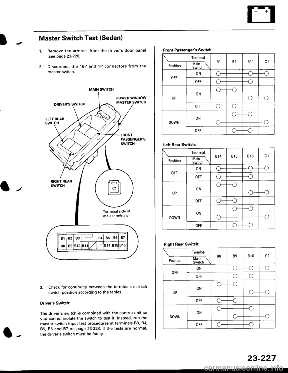
Master Switch Test (Sedan)
1.Remove the armrest from the driver's door panel
(see page 23-228).
Disconnect the 16P and 1P connectors from the
master switch.
Check for continuity between the terminals in each
switch position according to the tables
Driv€r's Switch:
The driver's switch is combined with the control unit so
you cannot isolate the switch to test it. Instead, run the
master switch input test procedures at terminals 83, 84,
85. BO and 87 on page 23-22A. lt the tests are normal,
the driver's switch must be faulty.
MAIN SWITCH
rFl
ll"'llt.:::::::l
B1B3B4B5B6B7
B889810811/l/leuBl5816
Terminalside of
male terminals
Front Passenger's Switch:
Terminal
P*,j--f$t,l"\B182811cl
OFFONCF--o
OFFooo
UPONo---o
o---o
OFFc\---o
DOWNON
o
oo
-o
OFFoo
Left Rear Swhch:
Terminal
P".r,-'-f-mn\814815816c1
OFFONG--o
OFFoo
UPONo--oo
o---o
OFFo-o
DOWNON
o-
o--o
o
OFFo--_o
Right Rear Switch:
Terminal
'**-T-*mB889B'�t0c1
OFFONo-o'o
OFFo---o
UPONo---o
CF--o
OFFCr---o
DOWNONo---.o
--oo-
OFFo---o
23-227
Page 1705 of 2189
Moonroof
a-/
Component Location Index
MOONBOOF SWITCHTest, page 23-236
. MOONROOF CLOSE RELAYlwire colors: WHT. GRN/YEL, lIGRN/oBN, BLK, and GRN/REDITest, page 23 87, 88. MOONROOF OPEN RELAY
f wire colors: WHT, cRN/RED,l
IGBN/ORN, BLK and YEL lTest, page 23'87, 88
MOONROOF MOTORTest, page 23-236
l-,
23-235
Page 1708 of 2189
Moonroof
1.
Switch Test
Carefully remove the switch from the driver's dash-
board lower cover {see page 23-205}.
Check for continuitv between the terminals in each
switch position according to the table.
Terminal
t*',*-----__\I234
ut-t-
OPENo--o
CLOSEo---o
TILTo--o
23-234
Motor Test
'1.Remove the headliner (see section 20).
Disconnect the 2P connector from the moonroof
motor.
Terminal side of male terminals
Check the motor by connecting power and ground
according to the table.
4. lf the motor does not run, replace it (see section 20).
NOTE: See Closing Force Check in section 20 for
motor clutch test.
\_____lTr1
Position
,l
OPENo@
CLOSE@
Page 1710 of 2189
Gruise Control
Component Location Index
MAIN SWITCHTesVReplacement,page 23-242CABLE REELReplacement, section 24
BRAKE SWITCH, fest, page 23-244. Pedal Height Adjustment,section 19CRUISE CONTROI. UNITInput Test, page 23-240
swrTcH {M/T). Test. page 23-244. Clutch Pedal Adjustment,section 12
atfSWTTCH. Test, page 23-154' Replac€ment, page 23-'155
ACTUATOR CABLEAdjustment, page 23-246
VACUUM TANK
TOR ASSEMBLY. Test, pag€ 23-245. Replacement, page 23-246. Solenoid Test, page 23-247' Disassembly, page 23-248
23-240