Page 1636 of 2189

Lighting System
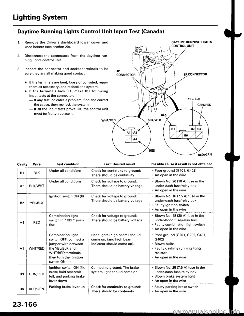
Daytime Running Lights Control Unit Input Test (Canadal
2.
3.
LRemove the driver's dashboard lower cover and
knee bolster (see section 20).
Disconnect the connectors from the daytime run-
ning lights control unit.
Inspect the connector and socket terminals to be
sure they are all making good contact.
lf the terminals are bent, loose or corroded. repair
them as necessary, and recheck the system.
lf the terminals look OK, make the following
input tests at the connector,- lf any test indicates a problem, find and correct
the cause, then recheck the system.- lf all the input tests prove OK, the control unit
must be faulty; replace it.
CavityWireTGst conditionTest: Desired resultPossible cause it result is not obtained
BLKU nderall conditionsCheck for continuity to g.ound:
There should be continuity.
. Poor ground (G401, G402). An open in the wire
A2BLK /VHT
Underall conditionsCheck for voltage to ground:
There should be battery voltage.
Blown No.20 (10 A) fuse in the
under-dash fuse/relay box
An open in the wire
etYEUBLK
lgnition switch ON (ll)Check for voitage to ground:
There should be battery voltage.
Blown No. 18 {7.5 A) fuse in the
under-dash luse/relay box
Faulty ignition switch
An open in the wire
A4RED
Combination light
switch in " =D " posi-
UOn
Check for voltage to ground:
There should be battery voltage.
Blown No. 48 (30 A) tuse in the
under-hood fuse/relay box
Faulty combination light switch
An open in the wire
A1WHT/RED
Combination light
switch OFF; connect ajumper wire between
the YEUBLK and
WHT/RED terminals,
then turn the ignition
switch ON (ll)
Headlights (high beam) should
come on, (and high beam
indicator should come on).
. Poor ground (G201, G202, G40'1,
G402). Blown bulbs. Faulty daytime running lights
resrstor. An open in the wire
GRN/RED
lgnition switch ON (ll),
brake fluid reservoir
full, and parking brake
lever down
Connect to ground: The brake
system light should come on.
Blown No.25 (7.5 A) fuse in the
under-dash f use/relay box
Blown brake system light
An open in the wire
REDiGRNParking brake lever LrpCheck for continuity to groundl
There should be continuity.
. Faulty parking brake switch. An open in the wire
23-166
Page 1637 of 2189

Headlights/Front Turn
Signal/Parking Lights
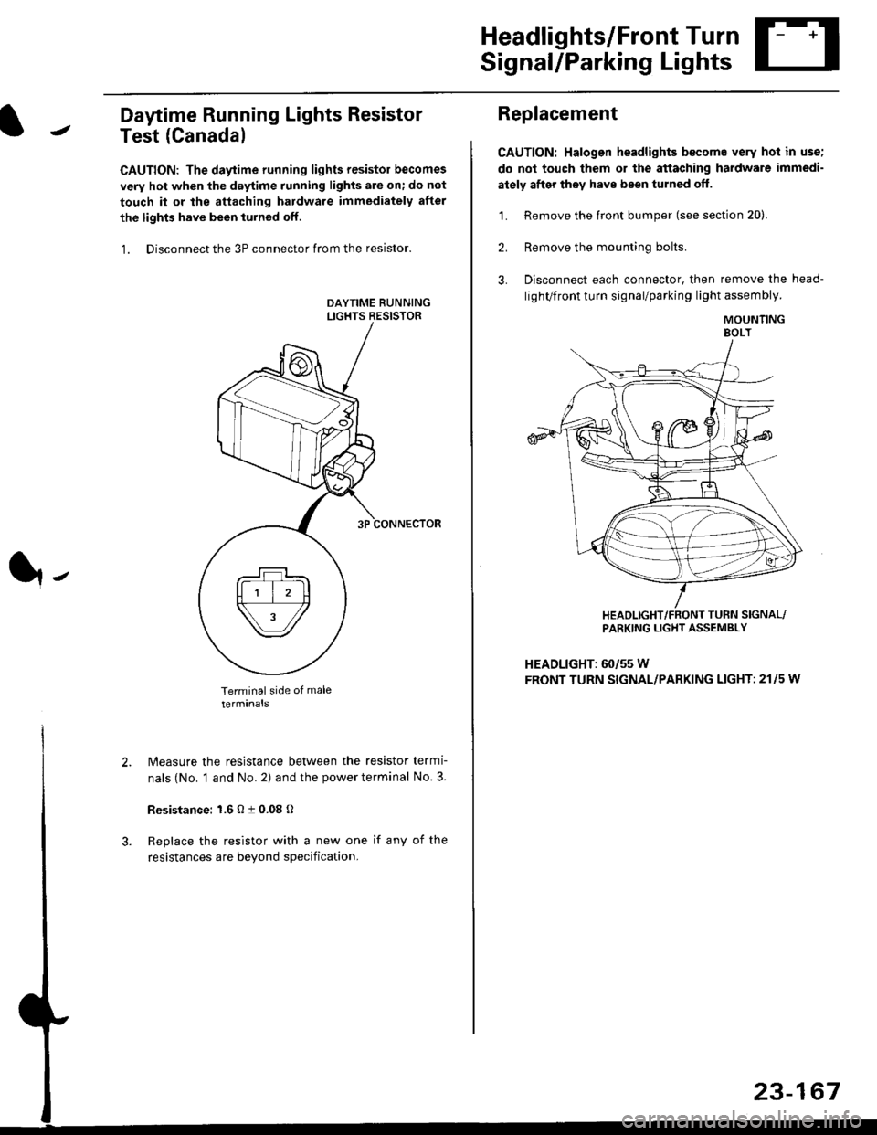
Daytime Running Lights Resistor
Test (Canada)
CAUTION: The daytime running lights resistor becomes
very hot when the daytime running lights are on; do not
touch il or the attaching hardware immediately after
the lights have been iurned off.
1. Disconnect the 3P connector from the resistor.
Terminal side of male
terminals
N4easure the resistance between the resistor termi
nals (No. 1 and No. 2) and the power terminal No. 3.
Resistance: 1.6 O t 0.08 O
Replace the resistor with a new one if any of the
resistances are beyond specification.
It-
Replacement
CAUTION: Halogen headlights b€come very hot in use;
do not touch them or the attaching hardware immedi-
ately after they have been turned off.
1. Remove the front bumper (see section 20).
2. Remove the mounting bolts,
3. Disconnect each connector, then remove the head-
lighVfront turn signal/parking light assembly.
MOUNTINGEOLT
HEADLIGHT/FRONT TUFN SIGNAL/PARKING LIGHT ASSEMBLY
HEADLIGHT: 60/55 W
FRONT TURN SIGNAL/PARKING LIGHT: 21l5 w
23-167
Page 1641 of 2189
Taillights
Replacement (Except'99 - 00 Sedanl
NOTE:
. Inspect the gasket; replace it il it is distorted or stays
compressed.
. After installing the taillights, run water over them to
make sure they do not leak.
Outer Taillights ('96 - 00 models, except'99 - 00 Sedan):
1. Open the trunk lid/hatch.
2. Disconnect the 4P or 6P connector trom the outer
taillight.
3. Remove the four mounting nuts, then pull out the
outer taillight.
l-
Hatchback:
BRAKE/TAILLIGHT: 2115W
TURN SIGNAL LIGHT: 21 W
BACK-UP LIGHT: 21 W
4P or 6P CONNECTOR
BRAKE/TAILLIGHT: 2115W
TURN SIGNAL LIGHT: 21 W
BRAKEiTAILLIGHT: 2115 W
BACK-UP LIGHT: 21 W
Inner Taillights (Coupe'96 - 00 models/Sedan'96 - 98
models):
1. Open the trunk lid, then remove the access panel.
2. Disconnect the 4P connector from the inner taillight.
3. Remove the four [three] mounting nuts, then pull
out the inner taillight.
I l: Sedan
Coupei
INNER TAILLIGHT
Sedan:
INNER TAILLIGHT
4P CONNECTOB
Page 1642 of 2189
Taillights
Replacement ('99 - 00 Sedanl
NOTE:
. Inspect the gasket; replace it if it is distorted or stays
compressed.
. After installing the taillights, run water over them to
make sure they do not leak.
Outer Taillights:
1. Open the trunk lid/hatch.
2. Disconnect the 4P and 2P connector trom the outer
taillight.
3. Remove the four mounting nuts, then pull out the
outer taillight.
TAILLIG}fi
4P CONNECTOR
BRAKE/TAILLIGHT: 2115W
TURN SIGNAL LIGHT: 21 W
r*i/et./
23-172
Inner Taillights:
'1. Open the trunk lid, then remove the access panel.
2. Disconnect the 3P and 2P connector from the inner
taillight.
3. Remove the three mounting nuts, then pull out the
inner taillight.
[ ]: Sedan
BRAKE/TAILLIGHT: 2r15 W
BACK.UP LIGHT: 21 W
3P CONNECTOR
Page 1645 of 2189
Hazard Warning Switch Test
CAUTION: Be careful not to damage the hazard warn-
ing switch or the center outlet panel when prying the
switch out.
'96 - 98 models:
'1. Pry the hazard warning switch out of the center out-
let panel.
2. Disconnect the 'l0P connector from the hazard warn-
ing switch.
3. Check for continuity between the terminals in each
switch position according to the table
HAZARDWARNINGlOP CONNECTOR
q-
Check for continuity between the terminals in
switch position according to the table.
Terminal No,4 is not used.
Terminal
t** \
12356I9l0
OFFoo
ot !.1o
ONo-ooo
o.o
o@o
'99 - 00 models:
1. Remove the center panel lsee section 20).
2. Remove the two screws, then remove the switch
from the center Panel
scREwsHAZARDWARNINGswlTcH
CENTER PANEL
.
Page 1646 of 2189
License Plate Lights
Replacement
'96 - 98 Sedan/Coupe:
L Remove the two screws from the license plate light,
and pull the light out pan ot the way.
2. Disconnect the 2P connector trom the light.
3. Take the lens off, then replace the bulb.
Hatchback/'gg - 00 Sedan:
1. Carefully pry the licence plate light out of the license
plate tnm.
2. Disconnect the 2P connector from the light.
2P CONNECTOR
2P CONNECTOR
23-176
Page 1651 of 2189

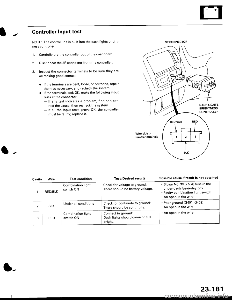
Controller Input test
NOTEr The control unit is built into the dash lights bright-
ness controller.
'1. Carefully pry the controller out of the dashboard.
2. Disconnect the 3P connector from the controller'
3. Inspect the connector terminals to be sure they are
all making good contact.
. lf the terminals are bent, loose, or corroded, repair
them as necessary, and recheck the system.
. lf the terminals look OK, make the following input
tests at the connector.- lf any test indicates a problem, find and cor-
rect the cause, then recheck the system.
- lf all the input tests prove OK, the controller
must be faulty; replace it
Cavity
Wire side of
lemale termlnals
Test condition Test Desited resultsPossible cause if rgsult is not obtainGd
1RE D/B LK
Combination light
switch ON
Check for voltage to ground:
There should be battery voltage.
Blown No.30 (7.5 A) fuse in the
under-dash Iuse/relay box
Faulty combination light switch
An open in the wire
2BLKUnder all conditionsCheck for continuity to ground:
There should be continuity.
. Poor ground (G401, G402)
. An open in the wire
RED
Combination light
switch ON
Connect to ground:
Dash Iights should come on full
bright.
. An open in the wire
23-181
Page 1655 of 2189
Ceiling Light Test
1. Turn the light switch OFF
2. Pry off the lens.
3. Remove the two mounting nuts (or a bolt) from the
housing, then remove the housing.
4. Disconnect the connector{s) from the housing.
5. Check for continuity between the terminals in each
switch position according to the table.
With moonroof:
3P CONNECTOR
rermrnal
Position \
12or2'
3or3'�
OFFo-/a\-o\7
MIDDLEo-,.\--o\:/
ONo---o\:/
23-185
q,
Without moonroot:
Coupe/Hatchback:
BULB (5 WI
/
2'
4
1
3