Page 1616 of 2189

Interlock System
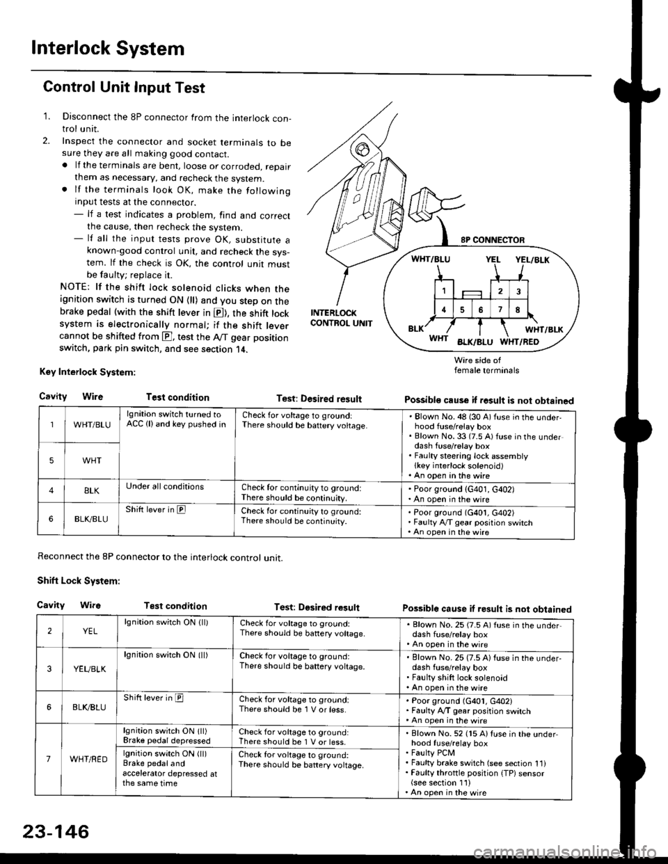
Control Unit Input Test
1. Disconnect the 8P connector from the interlock con-trol unit.
2. Inspect the connector and socket terminals to besure they are all making good contact.. lf the terminals are bent, loose or corroded, repairthem as necessary, and recheck the system.. lf the terminals look OK, make the followinginput tests at the connector.- lf a test indicates a problem, find and correctthe cause, then recheck the system.- lf all the input tests prove OK, substitute aknown-good control unit, and recheck the sys-tem. lf the check is OK, the control unit mustbe faulty; replace it.
NOTE: lf the shift lock solenoid clicks when theignition switch is turned ON {ll) and you step on thebrake pedal (with the shift lever in E), the shift locksystem is electronically normal; if the shift leve.cannot be shifted from E], test the Aff gear position
switch, park pin switch, and see section 14.
Key Interlock System:
CavityWireTest condition
Reconnect the 8P connector to the interlock control unit.
Shift Lock System:
Cavity WifsTest condition
INTERLOCKCONTROL UNIT
Test: Desired result
Test: Dgsired result
Wire side offemale terminals
Possible cause if result is not obtained
Possible cause if result is not obtained
WHT/BLU
lgnition switch turned toACC (lland key pushed inCheck for voltage to groundiThere should be baftery voltage.Blown No. 48 (30 A) fuse in the underhood fuse/relay boxBlown No. 33 (7.5 A) fuse in the underdash fuse/relay boxFaulty steering lock assemblylkey interlock solenoid)An open in the wire
5WHT
BLKUnder all conditionsCheck for continuity to ground:There should be continuity.
' Poor ground (G401, G402). An open in the wire
6BLK./BLUShift lever in ElCheck for continu;ty to ground:There should be continuity.Poor ground (G401, G402)Faulty Ay'T gear position switchAn open in the wire
2YELlgnition switch ON lll)Check for voltage to ground:There should be banery voltage.
. Blown No. 25 (7.5 A) fuse in the under,dash fuse/relay box. An open in the wire
3YEUBLK
lgnition swirch ON (ll)Check for voltage to ground:There should be baftery voltage.Blown No. 25 (7.5 A) fuse in the under-dash fuse/relay boxFaulty shift lock solenoidAn open in the wire
6BLI(BLUShift lever in ICheck for voltage to ground:There should be 1 V or less.Poor ground (G401, G402)Faulty A,/T gear position switchAn open in the wire
7WHT/RED
lgnition switch ON lll)Brake pedaldepressedCheck for voltage to ground:There should be 1 V or less.Blown No. 52 (15 A) Iuse in the underhood fuse/relay boxFaulty PCMFaulty brake switch (see section 1l)Faulty throttle position {TP) sensor(see section 1'l )An open in the wire
lgnition switch ON (ll)Brake pedalandaccelerator depressed atthe same time
Check for voltage to ground:There sho(Jld be battery voltage.
23-146
Page 1617 of 2189

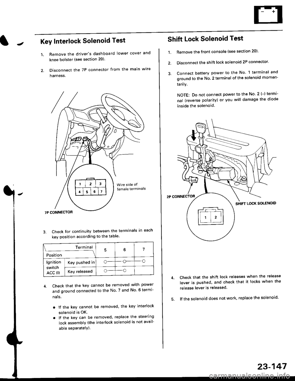
Key Interlock Solenoid Test
Remove the driver's dashboard lower cover and
knee bolster (see section 20)
Disconnect the 7P connector from the main w're
harness.
3. Check Ior continuity between the terminals in each
kev oosition according to the table'
4. Check that the key cannot be removed with power
and ground connected to the No. 7 and No 6 termi-
nals
. lf the key cannot be removed. the key interlock
solenoid is OK.
. lf the key can be removed, replace the steering
lock assembly (the interlock solenoid is not avail-
able seParatelY).
1.
Terminal
i*i,r"
- - --\7
lgnition
switch
ACC fl)
Key pushed ino--o
Key releasedo--o
Shift Lock Solenoid Test
't.Remove ths front console (see section 20)'
Disconnect the shift lock solenoid 2P connector'
Connect battery power to the No. 1 terminal and
ground to the No. 2 terminal of the solenoid momen-
Iarrry.
NOTE: Do not connect power to the No 2(-) termi-
nal (reverse polarity) or you will damage the diode
inside the solenoid
Check that the shift lock releases when the release
lever is pushed, and check that it locks when the
release lever is released
lf the solenoid does not work, replace the solenoid'
23-147
Page 1618 of 2189
Interlock System
Park Pin Switch Test
1, Remove the front console (see section 2Ol.
Disconnect the 4P connector from the park pinswitch.
Check for continuity between the No. 3 and No. 4terminals with:- the shift lever any position other than E, or- the push button pushed in E.There should be continuity.
Check for continuity between the No. 3 and No. 4terminals with the shift lever in E and the push but-ton released. There should be no continuiw. lf nec-essary, replace the park pin switch.
NOTE: Park pin switch 4p connector No. 1 and No.2terminals are lor Ay'T gear position console light.refer to the circuit diagram on page 23-1S0.
23-14A
Page 1622 of 2189
A/T Gear Position Indicator
1.
Indicator Input Test
Remove the gauge assembly from the dashboard (see page 23 135), and disconnect the 14p connector from rne gaugeassemblv.
Inspect the connector and socket terminals to be sure they are all making good contact.
. lf the terminals are bent. loose or corroded, repa ir them as necessary, and recheck the system.. lf the terminals look OK, make the following input tests at the 14p connector.- lf a test indicates a problem, find and correct the cause, then recheck the system.- lf all the input tests prove OK, but the indicator is faulty, replace the printed circuit board.
+1: Not used'2: AIT'3i CVT
l{P CONNECTOR "A"
REOBLU8RN
AIMA3A4A6
A8A9A10All412A13414
GRNLTBLK
GAUGE ASSEMBLY
23-152
Page 1624 of 2189
A/T Gear Position Indicator
A/T Gear Position Switch Test
1. Remove the front console (see section 2O).
2. Disconnect the 14P connector from the A/T gear position switch.
3. Check for continuity between the terminals in each switch position according to the table.
' Move the shift lever back and forth without pushing the shift lever at each switch position, and check for continuitywithin the range of free play of the shift lever.' lf there is no continuity within the range of free play, adjust the position of the switch as described on the nextpage.
Terminal side of male terminals
A/T Gear Position Switch
+ 1 : With cruise controlsystem
23-154
Eack - upLight SwitchNeutralPosition Switch
Page 1625 of 2189

A/T Gear Position Switch
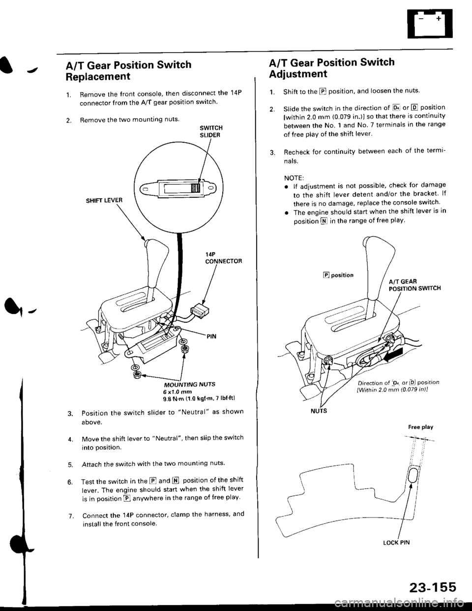
Replacement
1.
2.
7.
Remove the front console, then disconnect the
connector from the A/f gear position swltch
Remove the two mounting nuts
swrTcHSLIDEB
MOUNT'NG NUTS6x1 0mm98Nm(10kgtm'7lblftl
Position the switch slider to "Neutral" as shown
above.
Move the shift lever to "Neutral", then slip the switch
into position.
Aftach the swjtch with the two mounting nuts.
Test the switch in the E and E position ofthe shift
lever. The engine should start when the shift lever
is in position fl anywhere in the range of free play
Connect the 14P connector, clamp the harness, and
install the front console
14P
A/T Gear Position Switch
Adjustment
1.
3.
Shift to the E position, and loosen the nuts.
slide the switch in the direction of El or E position
lwithin 2.0 mm (0.079 in.)l so that there is continuity
between the No. 1 and No 7 terminals in the range
of free play of the shift lever'
Recheck for continuity between each of the termi-
nats.
NOTE:
. lf adjustment is not possible, check for damage
to the shift lever detent and/or the bracket lf
there is no damage. replace the console switch
. The engine should start when the shift lever is in
position N in the range of free play
E positionA/T GEARPOSITION SWITCH
Djrection of -on, or Dl Positionlwithin 2.0 mm (0.079 in)1
Free play
-lfr-
LOCK PIN
23-155
Page 1628 of 2189
Integrated Control Unit
Input Test
SRS components are located in this area. Review the SRS component locations, precautions, and procedures in the SRSsection {24) before performing repairs or service.
1. Remove the driver's dashboard lower cover and knee bolster (see section 20),
2. Disconnect the 10P connector from the integrated control unit.
3. Remove the integrated control unit from the under,dash fuse/relay box.
4. lnspect the connector and socket terminals to be sure they are all makjng good contact.
. lf the terminals are bent, loose or corroded, repair them as necessary, and recheck the system..lftheterminalslookOK,makethefollowinginputtestsattheconnectorandthefuse/relayboxsocket.
- lf any test indicates a problem, find and correct the cause, then recheck the system.- lf all the input tests prove OK, the control unit must be faulty; replace it.
INTEGRATED CONTROL UNIT
lOP CONNECTOR
Wire side otfemale terminals
23-158
Page 1635 of 2189

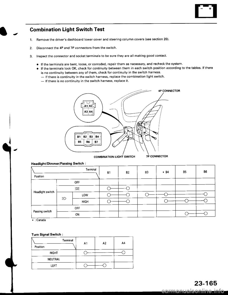
Combination Light Switch Test
1.Remove the driver's dashboard lower cover and steering column covers (see section 20)
Disconnect the 4P and 7P connectors from the switch.
Inspect the connector and socket terminals to be sure they are all making good contact
. lf the terminals are bent, loose. or corroded, repair them as necessary, and recheck the system.
. lf theterminals look OK, check for continuity between them ineach switch position according tothetables lfthere
is no continuity between any of them. check for continuity in the switch harness
- lf there is continuity in the switch harness. replace the combination light switch
- lf there is no continuity in the switch harness, replace it.
2.
4P CONNECTOR
COMBINATION LIGHT SWITCH7P CONNECTOR
HsadlighUDimmer/Passing Switch :
* : Canada
rrr r-l
l(rr mf ItffiTI A3 A11l
Terminal
Position
B182B3*84B586
Headlight switch
OFF
o---o
LOWo---oo-----o
HIGHo-----oo---o
Passing switchOFF
ONo-----o
Turn Signal Switch :
Teminal
;',*;----__\A1A2A4
RIGHToo
NEUTRAL
LEFToo
23-165