Page 1590 of 2189

Charging System
Alternator Replacement
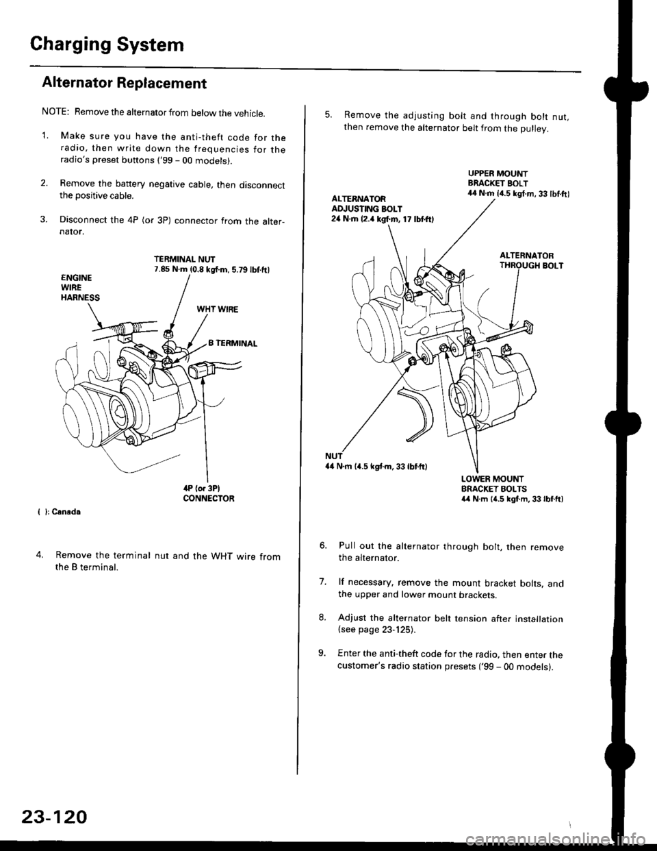
NOTE: Remove the alternator from below the vehicle.
'1. Make sure you have the anti-theft code for theradio, then write down the frequencies for theradio's preset buttons ('99 - 00 models).
2. Remove the battery negative cable, then disconnectthe positive cable.
3. Disconnect the 4P (or 3P) connector from the alter-naIor.
TERMINAL NUT7.85 N.m (0.8 kgf.m, 5.79lbf.ftl
{ }: Cansd.
4. Remove the terminal
the B terminal.
nut and the WHT wire from
23-120
5. Remove the adjusting bolt and through bolt nut,then remove the alternator belt from the Dullev.
UPPER MOUNTBRACKET BOLT44 N.m 14.5 kgt.m, 33 lbl.ftlALTERNATORAD.'USTING BOLT24 N.rh l2.a kgf.m, 17 lbtft)
ALTERNATORBOLT
a4 N.m 14.5 kstm.33lbf'ftl
LOWER MOUNTBRACKET BOLTSa4 N.m l{.5 kgf.m,33lbfft)
Pull out the alternator through bolt, then removethe alternator.
lf necessary, remove the mount bracket bolts. andthe upper and lower mount brackets
Adjust the alternator belt tension after installation(see page 23-125).
Enter the anti-theft code for the radio, then enter thecustomer's radio station presets ('99 - 00 models).
7.
Page 1599 of 2189
JGau ge/lndicator/Terminal
With tachometer;
CONNECTOR "A"
{A/T GEAR POSITION INDICATOR}
Location lndex
CONNECTOR "8"
{GAUGE and INOICATOR)CONNECTOB "C"
CONNECTOR "D"
{ABS INDICATORI
SPEEDOMETER:Indicates 60 km/h at 637 rpm or
60 mph at 1,025 rpm o{thevehicle speed sensor (VSS).
A/T GEAR POSITIONINDICATORSee page 23 149
TACHOMETER:Indicates 100 rpm at200 pulses per minuteol the ignition controlmodule (lCMi.FUEL GAUGEENGINE COOLANT TEMPERATURE (ECT) GAUGE
(cont'd)
23-129
(GAUGE end INDICATORI
A1-----------+816
JlltlllulllllrL
c1 --------->c13
1ililil{ilrL
oooo o 0006^
)og @ @ o^o @ )'l |. o
Fl- - -> F5E1_ _ -->E5D1- --+05
oo/ \oo
Gauge/Sending Unit Test, page 23-142
Page 1600 of 2189
Gauge Assembly
Gauge/lndicator/Terminal Location Index (cont'd)
Without tachometer:
CONNECTOR "A"
IA/T GEAR POSITION INDICATORICONNECTOR "8"
{GAUGE and INDICATOR}CONNECTOR "C"
(GAUGE and INDICAIORI
CONNECTOR "F"
{SRS INDICATOR)CONNECTOR "D"
{ABS INDICATORI
SPEEDOMETER:Indicates 60 km/h at 637 rpm or60 mph at 1,025 rpm ofthevehicle speed sensor (VSS).
ENGINE COOLANT TEMPERATUFE (ECT) GAUGEA/T GEAR POSITIONINDICATOFSee page 23 149FUEL
A1 ------> 46
----> al4
B1. - --------------->B16
JilililHililil1
C1-- - --------..+C13
JililHililL
Oo_o-o O 0006
lus 0 0 Bu-. )
oo/ \oo
23-130
Gauge/Sending Unit Test, page 23 142
Page 1605 of 2189
JRemoval
1. Remove the two screws from the instrument panel.
2. Remove the instrument panel.
CAUTION: Carefully remove the instrument panel without damaging the clips.
3. Tilt the steering wheel down with the tilt adjustment lever.
4. Spread a protective cloth over the steering column.
5. Remove the four mounting screws from the gauge assembly.
6. Pry the gauge assembly out, and disconnect all connectors from it
7- Take out the gauge assembly.
GAUGE ASSEMBLY
INSTRUMENT PANEL
23-135
Page 1610 of 2189
Vehicle Speed Sensor (VSSI
Troubleshooting
Before testing, inspect the No. 15 (7.5 A) fuse in the under-dash fuse/relay box.
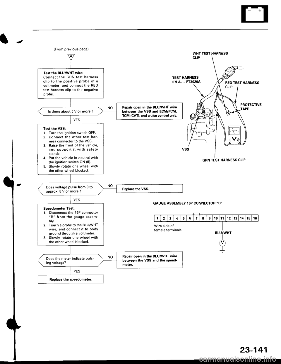
TEST HARNESSOTLAJ _ PT3O2OAREO TEST HARNESSCLIP
PROTECTIVETAPE
TEST HARNESSOTLA' . PT3O2OA
(To next page)
Test the BLK wire:1. Disconnect the 3P connectorfrom the vehicle speed sensor(vss).
2. Connect the test harness(07LAJ PT30200) only to theengine wire harness,3. Connect the RED test harnessclip to the positive probe of a
4. Check for continuity betweenthe RED test harness clip andbody ground.
Repair opon in the BLK wireb€twe€n the VSS and G101.ls there continuity?
Te3t the BLK/YEL wire:1. Connect the WHT test harnessclip to the positive probe of avoltmeter, and connectthe REDtest harness clip to the negativeprobe.2. Turn the ignition switch ON {ll).
Repair open in iho BLK/YEL wirebetween the VSS and the under-d6sh tuse/relav box.
vss
GRN TEST HARNESS
RED TEST HARNESS
WHT TEST HARNESS CLIP
23-140
Page 1611 of 2189

J
(From prevaous page)
WHT TEST HARNESSCLIP
TEST HABNESS07LAJ - Plil020aRED TEST HARNESSCLIP
PROTECTIVEAPE
GRN TEST HARNESS CLIP
GAUGE ASSEMBLY 16P CONNECTOR "8"
BLU
23-141
Tost the BLU/WHT wireiConnect lhe GRN test harnessclip to the positive probe of avoltmeter, and connect the RED
test harness clip to the negativeprobe.
Repair open in the BLU/WHT wirob€twoon the VSS and ECM/PCM,TCM (CVT), and cruise control untt.ls there about 5 V or more ?
Test the vss:1. Turn the ignition switch OFF.2. Connect the other test harness connector to the VSS.3. Raise the front ot the vehicle,and support it with safetystands,4. Put the vehicle in neutral with
the ignition switch ON (ll).
5. Slowly rotate one wheel withthe other wheel blocked.
Does voltage pulse from 0 toapprox.5 V or more ?
Speedometer Tosii'1. Disconnect the 16P connector"B" from the gauge assem-blv.2. Touch a probe to the BLUMHTwire, and connect it to bodyground through a voltmeter.
3. Slowly rotate one wheel with
the other wheel blocked.
Repair open in the BLU/WHT wi.ebelween th€ VSS and the 3pe€d-Does the meter indicate puls-
ing voltage?
female terminals
Page 1612 of 2189

Fuel Gauge
Gauge/Sending Unit Test
!@ Do not smoke while working on tho fuel
system. Keep open tlame away trom your wotk atea.
NOTE: Refer to page 23-133 for the fuel gauge system
circuit.
'1. Check the No. 25 (7.5 A) fuse in the under-dash fuse/
relay box before testing.
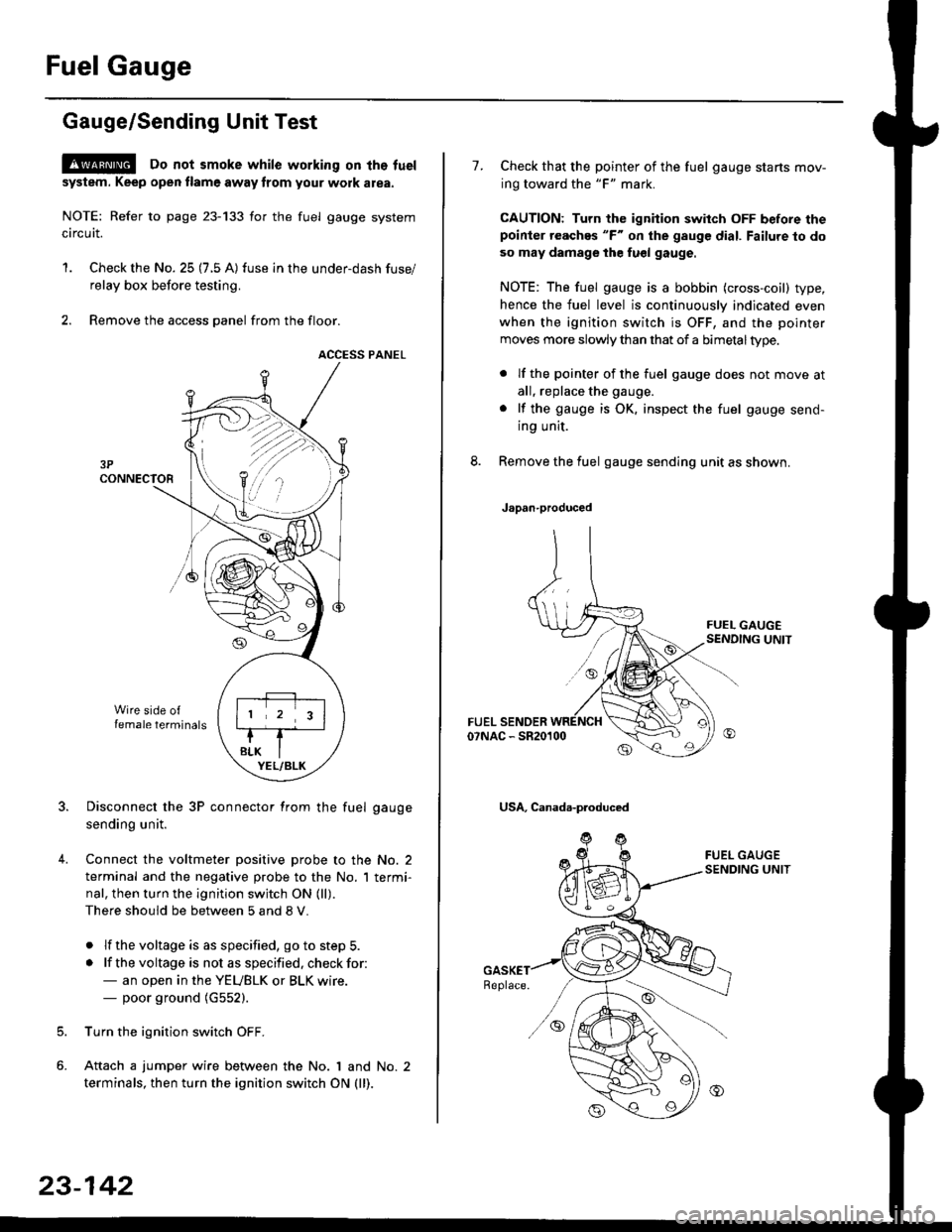
2. Remove the access panel from the floor.
ACCESS PANEL
Disconnect the 3P connector from the fuel gauge
sending unit.
Connect the voltmeter positive probe to the No. 2
terminal and the negative probe to the No. I termi-
nal, then turn the ignition switch ON (ll).
There should be between 5 and 8 V.
. lf the voltage is as specified, go to step 5.
. lf the voltage is not as specified. check for:- an open in the YEUBLK or BLK wire.- poor ground (G552).
Turn the ignition switch OFF.
Attach a jumper wire between the No. 1 and No. 2
terminals, then turn the ignition switch ON (ll).
)\
23-142
1.Check that the pointer of the fuel gauge starts mov-
ing toward the "F" mark.
CAUTION: Turn the ignition switch OFF before thepoinier reaches "F" on ihe gauge dial. Failure to do
so may damage the fuel gauge.
NOTE: The fuel gauge is a bobbin (cross-coil) type,
hence the fuel level is continuously indicated even
when the ignition switch is OFF, and the pointer
moves more slowly than that of a bimetaltype.
. lf the pointer of the fuel gauge does not move at
all, replace the gauge.
. lf the gauge is OK. inspect the fuel gauge send-
ing unit.
Remove the fuel gauge sending unit as shown.
Japan-produced
USA, Canada-produced
Page 1613 of 2189

J
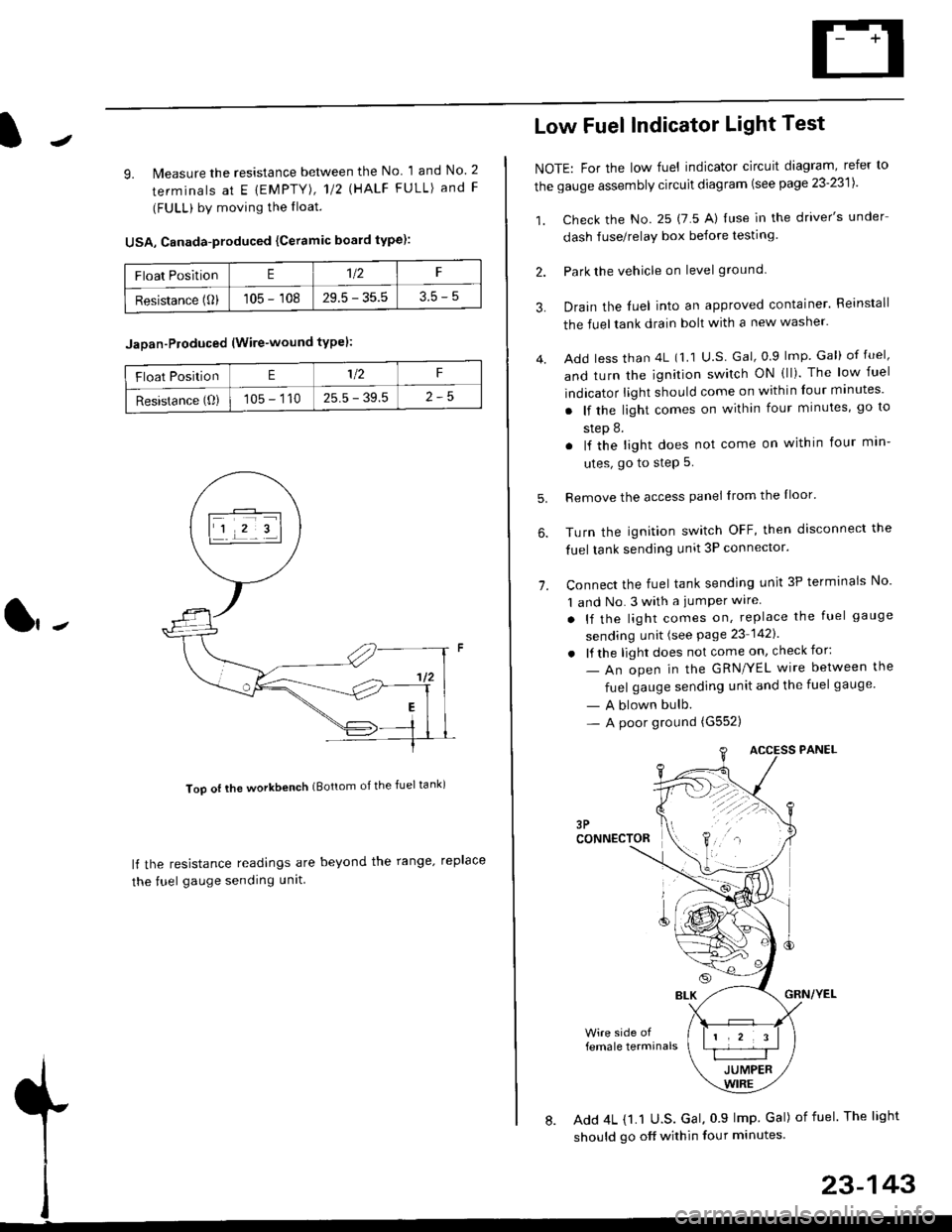
9. lMeasure the resistance between the No 1 and No. 2
terminals at E {EMPTY), 112 \HALF FULL) and F
(FULL) by moving the lloat.
USA, Canada-produced {Ceramic board type):
Too ot lhe workbench (Bottom of the fuel tank)
ll the resistance readings are beyond the range. replace
the fuel gauge sending unit
Float PositionE1t2F
Resistance (0)105 - 10829.5 - 35.53.5-5
Jaoan-Ploduced (Wire-wound typel:
Float PositionE1/2F
Resistance (O)105 - 11025.5 - 39.5
Low Fuel Indicator Light Test
NOTE: For the low fuel indicator circuit diagram, refer to
the gauge assembly circuit diagram (see page 23'2311.
1. Check the No. 25 (7 5 A) luse in the driver's under
dash fuse/relay box before testing
2. Park the vehicle on level ground.
3.
4.
Drain the luel into an approved container. Reinstall
the fueltank drain bolt with a new washer.
Add less than 4L (1 1 U.S Gal, 0.9 lmp Gal) of fuel,
and turn the ignition switch ON (ll). The low fuel
indicator light should come on within four minutes'
. lf the light comes on within four minutes, go to
step 8.
. lf the light does not come on within four min-
utes, go to step 5.
Remove the access panel lrom the Iloor'
Turn the ignition switch OFF, then disconnect the
fuel tank sending unit 3P connector.
Connect the fuel tank sending unit 3P terminals No'
1 and No. 3 with a jumPer wire
. lf the light comes on, replace the fuel gauge
sending unit (see Page 23 1421
. lf the light does not come on, check for:
- An open in the GRN/YEL wire between the
fuel gauge sending unit and the fuel gauge
- A blown bulb.- A poor ground (G552)
6.
1.
female terminals
8. Add 4L {1.1 U.S. Gal, 0 9 lmp Gal) of fuel The light
should go off within four minutes.
23-143