Page 1413 of 2189

Heater Unit
Replacement
SRS components are located in this area. Review the
SRS component locations, precautions, and procedures
in the SRS section {24} before performing repairs or ser-
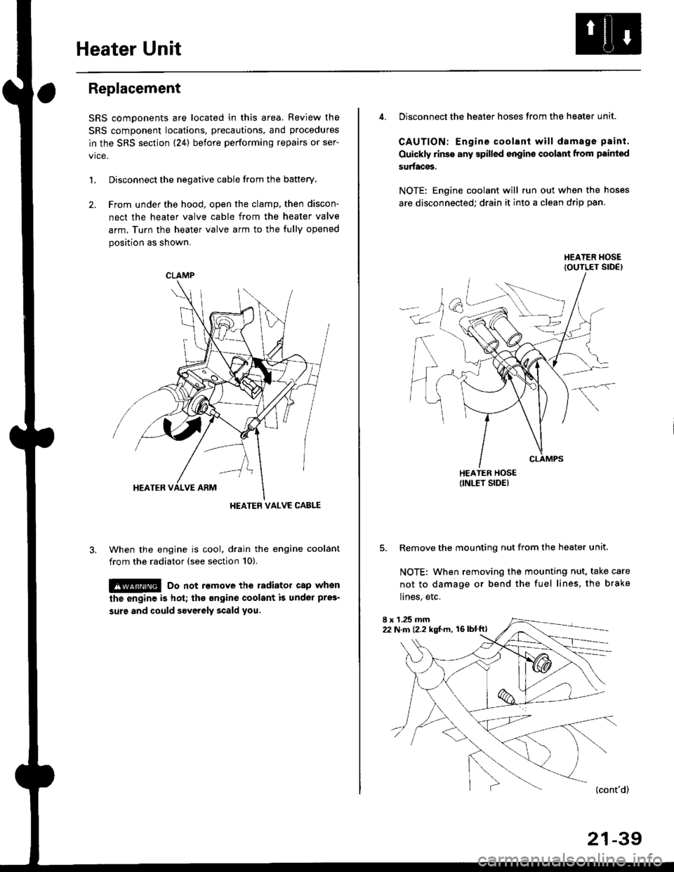
L Disconnect the negative cable from the battery.
2. Frcm under the hood, open the clamp, then discon-
nect the heater valve cable from the heater valve
arm. Turn the heater valve arm to the fully opened
position as shown.
When the engine is cool. drain the engine coolant
from the radiator (see section 10).
!@ Do not remove the radiator cap when
the engine is hot; the ongine coolant is under pres'
surg and could severely scald you.
CLAMP
HEATER VALVC CABLE
4. Disconnect the heater hoses from the heater unit.
CAUTION: Engine coolant will damage p8int.
Ouickly rinse any spilled engins coolant from painted
su aces,
NOTE: Engine coolant will run out when the hoses
are disconnected; drain it into a clean drip pan.
5. Remove the mounting nut from the heater unit.
NOTE: When removing the mounting nut, take care
not to damage or bend the fuel lines, the brake
lines, etc.
I x 1 .25 mm22 N.m {2.2 kgl.m, 16lblftl
21-39
Page 1532 of 2189
Fuses
Under-hood Fuse/Relay Box
cgo1lTo condensor fan relayl
Gr02lTo blower motor r€layl
c903*: Not usod
NOTE; View from the backside of the under-hood fuse/relav box.
[To radi.lor tan rolayl
cto5[To main wir6 harne$ (C3521]
fto l/c comprdssor]
lclutch relay I
c905lTo main wire ha.ness (C353ll
DE
tr
tr
tr
r-1
IJ
r"l17LI
n51
IJ
r"l56
LI
r"l57IJ
23-62
ITo main w;re ha.ness (C351ll
Page 1534 of 2189
Fuses
Under-dash Fuse/Relay Box
c912lTo d.rhborrd wire harnes lC50'l)l
c€l1lTo SRS m.in
c9l0lTo moonroofwiro h.tn6s 1C712)l
c913[To ignition 3witchllTo m.in wir. ha]n.3s {Cra2iIll
clr15
lTo m.in wiro h.Jna3r lca23)l
lTo powor window rcl.yl
c!17lTo tu]n .ign.l/h.z.rd r.byl
d.fogg.r rol.yl
.: Canadt*: Not usod
O: C326 loption (+B)l
@: C927 loption ld.3h light!)l
O: C!r28 loption tAOCll@: c!t29 loption (lc2ll
: Not u3od l'96 -97 modelll
NOTE: View from the backside of the under-dash fuse/relay box.
Clt25 (96, 97 mod.bl
lTo m.in wiro ha]n.!. (C439ll
a-) r"r r"t r-r n rl 11 r'l |;l r-r r-'l r-'l r-l23 2a 25 26 21 2A A aO3t 32 33LI IJ IJ IJ IJ IJ IJ LJ LJ LJ tJ tJ
r-r r-r Fr r-r r-r n n ra r-1 rat n r-1t2 t3 ra 15 16 17 1A 1a 20 21 22LI IJ IJ IJ IJ IJ LI IJ IJ LI I"J tJ
- rfl |?t - n n rn r-'l n rat T1 T1 T"l T"lt23a56r39tollLI I.J LI LI I.J LI I.J LI LI IJ IJ IJ LJ LI
23-64
lTo m.in wiro h!rn..s 1C419)l
Page 1555 of 2189

Under-dash Fuse/RelaY Box
Removal/lnstallation
SRS components are located in this area. Review lhe
SRS component locations, precautions, and procedures
in the SRS section (24) before performing repairs or ser-
vice.
Removal:
1. Make sure you have the anti-lheft code for the radio
then write down the frequencies lor the radio's pre-
set buttons ('99 - 00 modelsl.
2. Disconnect the battery negative cable. then discon
nect the positive cable, and wait at least three min
utes,
3. Disconnect the airbag connectors (see section 24)'
4. Remove the driver's dashboard lower cover and
knee bolster (see section 20)
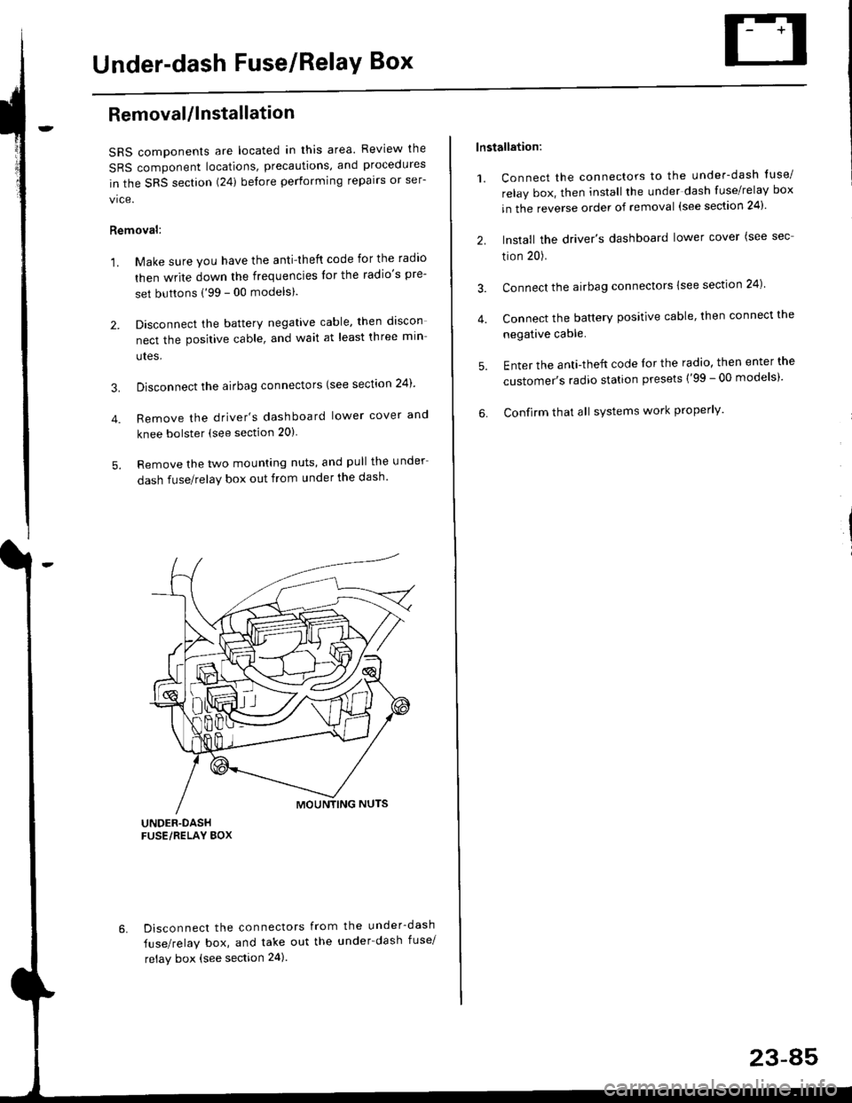
5. Remove the two mounting nuts, and pull the under
dash fuse/relay box out from under the dash'
6. Disconnect the connectors from the under-dash
fuse/relay box, and take out the under-dash fuse/
relay box (see section 24).
lnstallation:
1. Connect the connectors to the under-dash tuse/
relay box, then install the under dash fuse/relay box
in the reverse order of removal (see section 24)'
2. Install the driver's dashboard lower cover (see sec
tion 20).
3. Connect the airbag connectors {see section 24)
4. Connect the battery positive cable, then connect the
negative cable.
5. Enter the anti-theft code lor the radio, then enter the
customer's radio station presets ('99 - 00 models)'
6. Confirm that all sYstems work properly'
23-45
Page 1559 of 2189

lgnition Switch
4.
Test
SRS components are located in this area Review the
SRS component locations. precautions. and procedures
in the SRS section {24} before performing repairs or ser-
1. i/ake sure you have the anti-theft code for the
radio, then write down the frequencies for the
radio's preset buttons ('99 - 00 models).
2. Disconnect the battery negative cable.
3. Remove the driver's dashboard lower cover and
knee bolster (see section 20).
Disconnect the 5P connector from the under dash
fuse/relay box and the 7P connector from the main
wire harness.
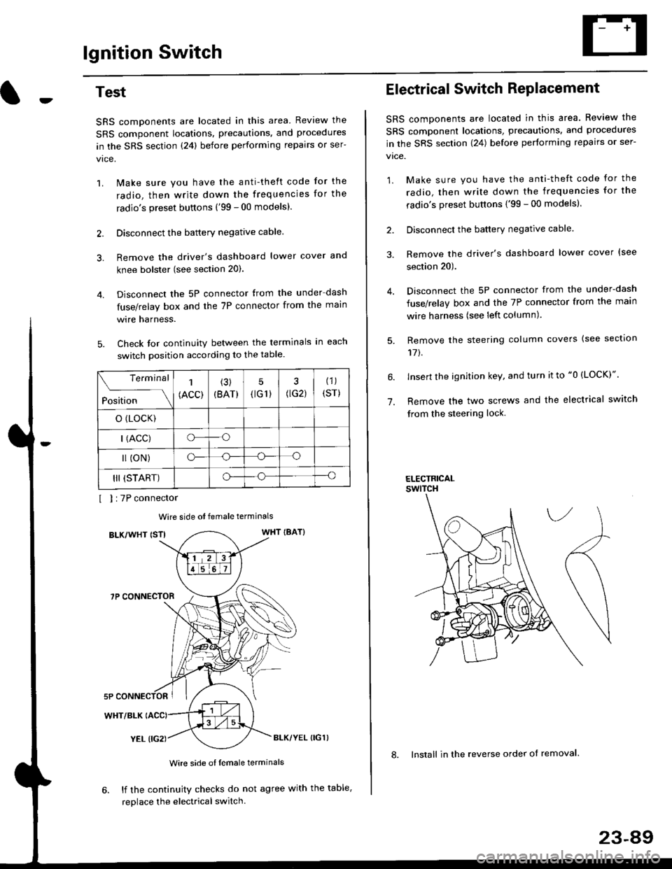
Check for continuity between the terminals in each
switch position according to the table.
I I :7P connector
Wire side ot female terminals
BLK/WHT {STIWHT IBAT}
7P CONNECTOR
WHT/BLK
YEL (IG2}BLK/YEL {IG1)
Wire side of female terminals
6. lf the continuity checks do not agree with the table,
replace the electrical switch.
Terminal
Position
1
(ACC)
(3)
(BAT)
5
{tG1) G2)
(1)
(sr)
o (LocK)
| (ACC)o--o
l (oN)o-o
III (START)o--o
1.
Electrical Switch RePlacement
SRS components are located in this area. Review the
SRS component locations, precautions, and procedures
in the SRS section \24) belore performing repairs or ser-
vtce.
1. Make sure you have the anti-theft code for the
radio, then write down the frequencies for the
radio's preset buttons {'99 - 00 modelsl.
2. Disconnect the battery negatlve cable.
3. Remove the driver's dashboard lower cover {see
section 20).
Disconnect the 5P connector from the under-dash
fuse/relay box and the 7P connector from the main
wire harness (see left column).
Remove the steering column covers {see section
11t.
lnsert the ignition key, and turn it to "0 {LOCK)".
Remove the two screws and the electrical switch
from the steering lock.
ELECTRICALswtTcH
8. Install in the reverse order of removal.
23-a9
Page 1560 of 2189

lgnition Switch
Steering Lock Replacement
SRS components are located in this area. Review theSRS component locations. precautions, and procedures
in the SRS section (24) before performing repairs or ser-vtce.
Remove:
LMake sure you have the anti-theft code for theradio, then wire down the frequencies for theradio's preset buttons ('99 - 00 models).
Disconnect the battery negative cable.
Remove the driver's dashboard lower cover andknee bolster (see section 20).
Disconnect the 5P connector from the under-dash
fuse/relay box and the 7P connector from the mainwire harness (see previous page).
Remove the steering column covers, then removethe mounting bolts and nuts from the steering col-umn (see section l7).
Lower the steering column assembly,
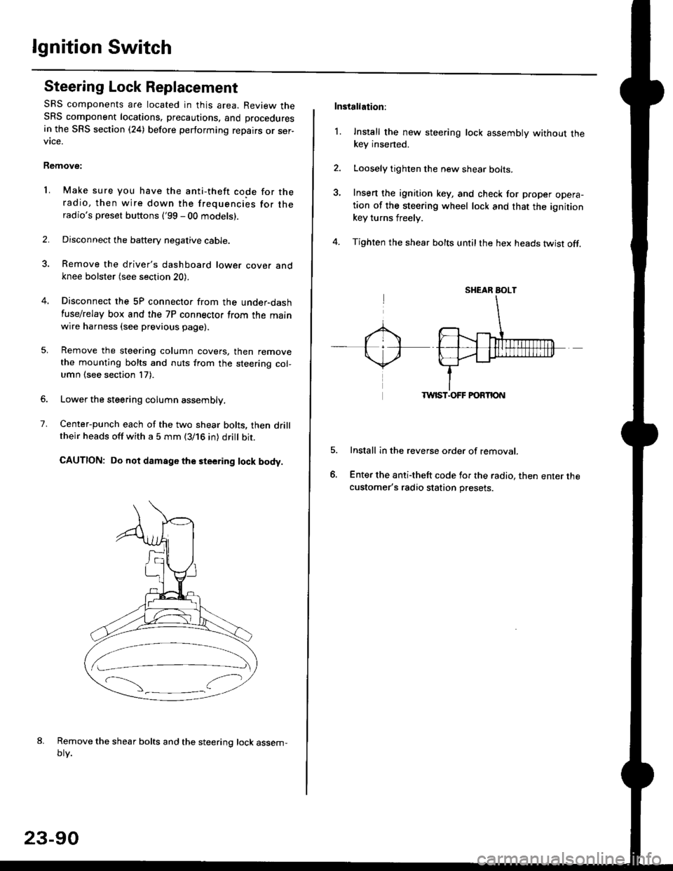
Center-punch each of the two shear bolts, then drilltheir heads off with a 5 mm (3/16 in) dritt bit.
CAUTION: Do not damago the steering lock body.
Remove the shear bolts and the steering lock assem,oty.
2.
1.
23-90
Installation:
l. Install the new steering lock assembly without thekey insened.
Loosely tighten the new shear bolts-
Insert the ignition key, and check for proper opera-tion of the steering wheel lock and that the ignitionkey turns freely.
Tighten the shear bolts untilthe hex heads twist off.
TWIST.OFF FORTION
Install in the reverse order of removar.
Enter the anti-theft code for the radio, then enter thecustomer's radio station presets.
sr{€aR SroLT
Page 1598 of 2189
Gauge Assembly
Component Location Index
SRS components are located in this area. Review the SRS component locations, precautions, and procedures in the SRS
section (24) before performing repairs or service.
6x1.0mm9.8 N.m 11.0 kgf.m,22lbt.lrl
VEHICLE SPEED SENSOR {VSS)Troubleshooting, page 23-1 40
GAUGE ASSEMBLYGau ge/lndicator/TerminalLocation Index, page 23-129Removal, page 23-135Bulb Location, page 23-136Disassembly, page 23 138
PARKING BRAKE SWITCH
FLUIO LEVEL SW]TCH
23-128
ENGINE OIL PR€SSURE SWITCH
Page 1619 of 2189
A/T Gear Position Indicator
Component Location lndex
sRS components are located in this area. Review the sRS component locations, precautions, and procedures in the sRS
section (241 before performing repairs or service'
A/T GEAR POSITION INDICATOR
Input Test, page 23-152
A/T GEAR POSITION SWITCHTest, page 23 154Replacement, page 23-155
t
E
N
E
E
E
(A/TI
E
N
E
E
r
(cw)
23-149