Page 344 of 2189
c122
A,g
l-iln'eo*r,vHr__-ll[lcRNiBLitl]l
cl17
r'trTl
16lBLK,-__-llO BLX,\,E[ |
16l Btu/wil-
c112
ffi
Cliro
o
C1'11
ffi
l6l-ciN/YEL' _-l
NOTE: . Different wires with the same color have been given a number suffix to distinguish them (for example, YEUBLK1
and YEUBLK'�are not the same).
O: Related to Fuel and Emissions System,- Connector with male terminals (double outline): View from terminal side
- Connector with female terminals (single outline): View from wire side
c'54*1
frl zlsl
fflErKwH---llOlBLr I
f6lGrrunEp -l
11-75
Page 346 of 2189
v1s8l7l6le t0r l!21
' S€cuitAr.h Sysi.m
cL5lwithod cruir. cort?oll
c510 ta/T)
;--F--trt2l
w
l-T - --l
l. - I
elz5{with crui* codrol)
r'ffitr
13 rl
lElwHT"cRN I
YELf,ED/BLK.!
- Connector with male terminals (double outline): View from terminal side
- Connector with female terminals (single outline): View from wire side
Different wires with the same cotor have been given a number suffix to distinguish them (for example, YEUBLKl
and YEUBLK'�are not the same).
O; Related to Fuel and Emissions System
Dt!
t-
NOTE: o
a
a(cont'd)
11-77
t213t5
5
14i!aL(LTATU
1
Et0t1,/ ./ie /1Al,/ 20
2a
9t0l213111 /l61718
!t
t1t
23I7a9
101112t3/lr5l/18 t9
12
YEL
YEL3LK2
Page 348 of 2189
c130
I10
l112131,4t5ta11t8t9
ct3r
1lz3lt/X61789to
cr34 tEcM/PCM-C)cr35 lPCM-Dr:cr35lPcl|.D,€
ca32
lr 2 3.1
IiGTNiBN Ill
l5l-wxr,nol]ll:a BLX vHI I
NOTE; . Different wires with the same color have been given a number suffix to distinguish them (for example, YEUBLK1
and YEUBLK, are not the samel.
O: Related to Fuel and Emissions Svstem.- Connector with male terminals (double outline): View from terminal side
- Connector with female terminals (single outline): View from wire side
lrl2l
lll* -_-l
tn Bs I
c1a
lr 2l
f.fil
,bl onrrwlrl.lftlBLrwHri-Flirx,lvHJ l]-l
c,|52 tEcM/PCM-Al
\-a
't/3l-1.51
/tgto 'lt12l3
2at6IE e t|0111'12ItItIt[l
11-79
Page 349 of 2189
System Descriptions
System Connectors lFuel Pump]
('9!, - 00 models 6xcept Dl6Y5 ongino with M/T)
\(
I
c568
ffi
c565
E
c792
Different wires with the same color have been given a number suffix to distinguish them (for example, YEUBLKIand YEVBLK, are not the same).
O: Related to Fuel and Emissions System.- Connector with male terminals (double outline): View from terminal side- Connector with female terminals (single outline): View from wire side
c793
fr
NOTE: o
a
a
1 1-80
Page 816 of 2189

Valve Caps
Description
Caps with one projected tip and one flat end are
installed with the flat end toward the inside of the
valve body.
Caps with a projected tip on each end are installed
with the smaller tip toward the inside of the valve
body. The small tip is a spring guide.
Toward outside of valvo body.
Toward insido ot valvo body.
Caps with one projected tip and hollow end are
installed with the tip toward the inside of the valve
body. The tip is a spring guide.
Towa.d outside o, valv6 bodv.
I
14-138
Toward insid€ of valv6 bodv.
Caps with hollow ends are installed with the hollow
end away from the inside ofthe valve body.
Caps with notched ends are installed with the notch
toward the inside of the valve body.
Caps with flat ends and a hole through the center are
installed with the smaller hole toward the inside of
the valve bodv.
Toward outsido of valve bodv.
Efla
Toward inlido ot valve bodv,
Caps with flat ends and a groove around the cap are
installed with the grooved side toward the outside of
the valve body.
Toward oulsido of valv6 body.
"-\"h
,A
\za9
Sectional view.
Toward insido ol valvo body.
Page 821 of 2189
CHECK BALL
w
MAIN VALVE BODY(Sectional viewl
SPRING SPECIFICATIONS
CHECK BALLS
CHECK BALLS
Unit: mm (in)
No.Springs
Standard (New)
Wire Dia.o.D.Free LengthNo. ot Coils
o
@
@
@
@
@
Relief valve spring
Modulator valve spring
CPB valve spring
1-2 shift valve spring
2nd orifice control valve spring
Servo control valve spring
1.1 (0.043)'1.4 (0.055)
0.9 (0.035)
0.9 (0.035)
0.7 (0.028)
1.0 (0.039)
8.6 (0.342)
9.4 (0.374)
8.1 t0.3221
7.6 {0.302)
6.6 (0.262)
8.'t to.322l
37.1 (1.461)
35.0 (1.378)
47.2 (1.8s8)
41.3 (1.6261
34.8 (1.370)
52.1 t2.O51l
13.4
10.91C ?'15.3
22.0
20.8
1+143
Page 1059 of 2189

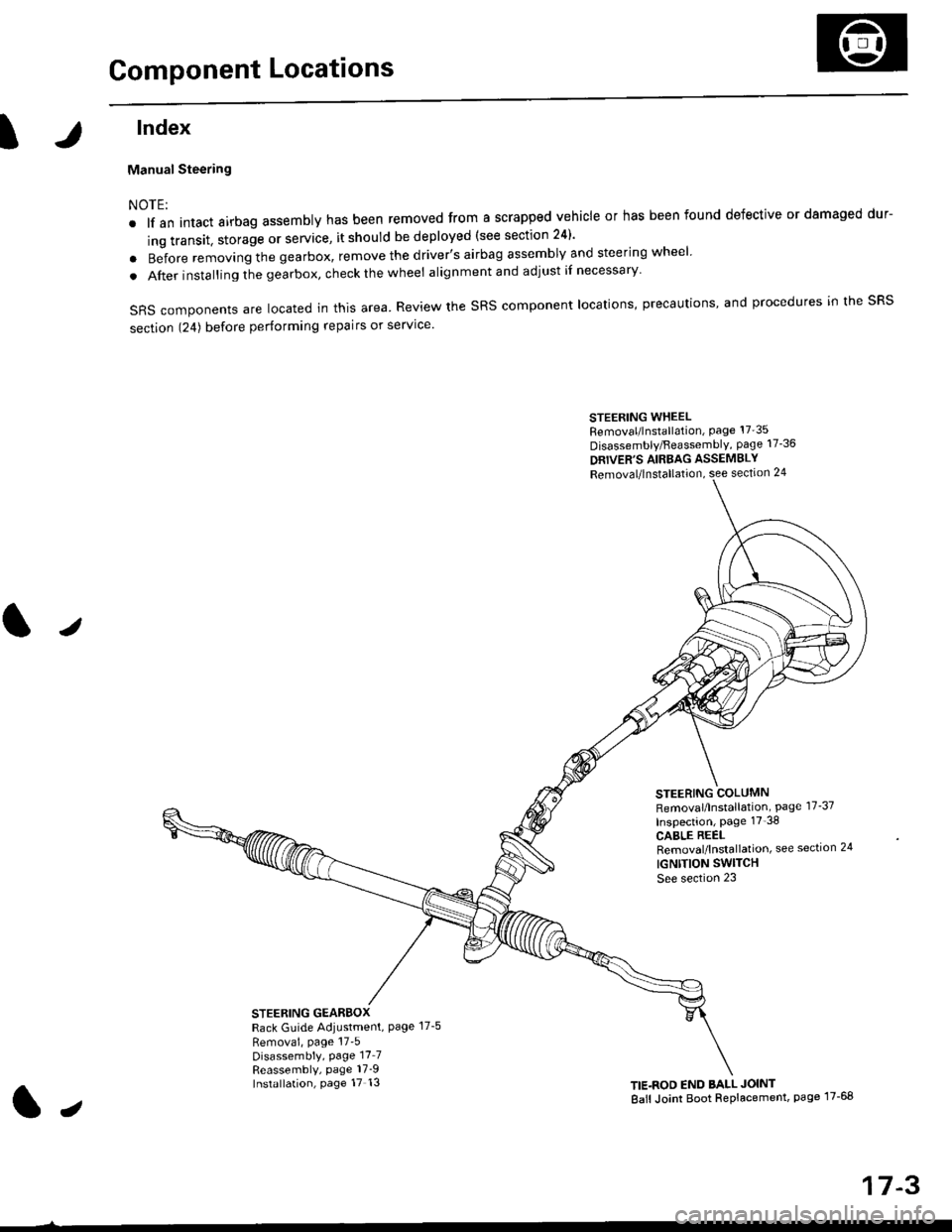
Component Locations
tlndex
Manual Steering
NOTE:
. lf an intact airbag assembly has been removed from a scrapped vehicle or has been found defective or damaged dur-
ing transit. storage or service, it should be deployed (see section 24)'
o Before removing the gearbox, remove the driver's airbag assembly and steering wheel
. After insta lling the gearbox, check the wheel alignmentand adjust if necessary
SRS components are located in this area. Review the SRS component locations, precautions, and procedures in the SRS
section 124) before performing repairs or service'
STEERING WHEELRemoval/lnstallation, Page 17'35
Disassembly/FeassemblY, page 17-36
DRIVER'S AIRBAG ASSEMBLY
Removal/lnstallation, see section 24
STEERING COLUMNRemoval/lnstallation, Page 17-37
Inspection, page 17'38
CABLE REELRemoval/lnstallation, see section 24
IGNTTION SWITCH
See section 23
STEERING GEARBOXRack Guide Adiustment, Page 17-5
Removai, page 17'5Disassembly, Page 17_7Reassembly, page 17_9Installation, page 17 13TIE.ROD END BALL JOINT
Ball Joint Boot Replacement, page 17-68
J
t,
17-3
Page 1068 of 2189
Steering Gearbox
Reassembly (cont'd)
21.
'19.
20.
Install the boot band so that the locking tabs of the
band (stake points) are in the range shown below.
{Tabs should face up and slightly forwaro.,
Bend both sets of locking tabs.
Lightly tap on the doubled-over portions to reduce
their height.
CAUTION: Stake the band locking tabs firmly.
22. Slide the rack right and left to be certain that the
boots are not detormed or twisted.
Stake points
+ Fronr
Lett Boot Band(Viewed from the left side)Right Boot Bend(Viewed from the right side)
17-12