1996 HONDA CIVIC left turn
[x] Cancel search: left turnPage 1606 of 2189
Gauge Assembly
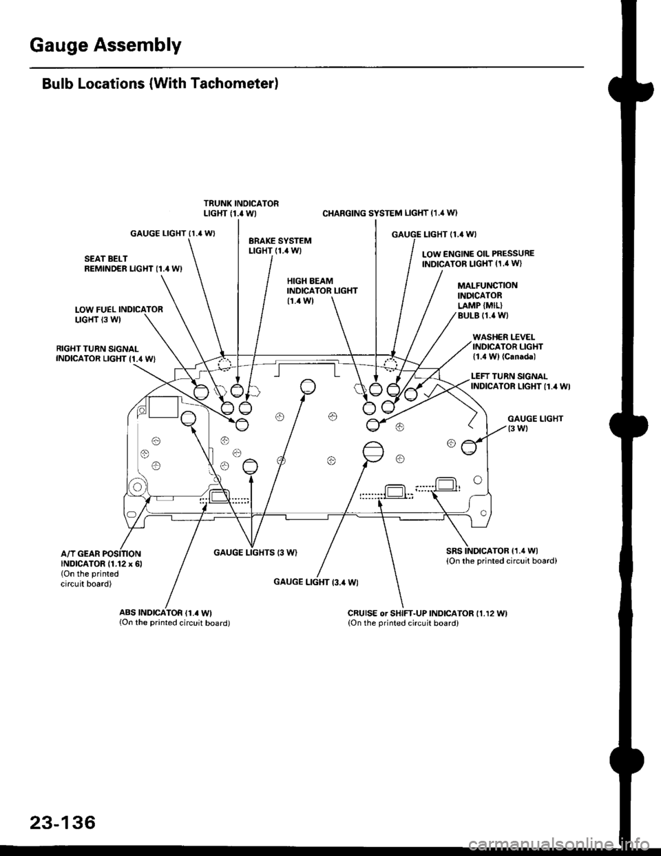
Bulb Locations (With Tachometer)
GAUGE LIGHT II.' WI
SEAT BELTREMINDER LIGHT I1.4 WI
LOW FUELLIGHT 13 W)
RIGHT TURN SIGNALINDICATOR LIGHT I1.4 WI
A/T GEARGAUGE LIGHTS 13 W)
CI{ARGING SYSTEM LIGHT (1.,1W)
GAUGE I-IGHT {1,4 WI
LOW ENGINE OIL PRESSUREINDICATOR LIGHT (1,' W}
HIGH EEAMINDICATOR LIGHT(1.4 W)
GAUGE LIGHT l3.il Wl
MALFUNCTIONINDICATORLAMP {MIL}BULE (1.{ Wl
WASHER I.'C VELINDICATOR LIGHT{1.4 Wl (Canada)
LEFT TURN SIGNALINDICATOR LIGHT {1.4 WI
sRsTOB (1.4 Wl
{On the printed circuit board)INDICATOR (1.12 x 6l(On the printed
circuit board)
ABS |ND|CATOR (1.. Wl{On the printed circuit board)CRUISE or SHIFT-UP INDICATOR 11.12 11.{On the orinted circuit board)
23-136
Page 1607 of 2189
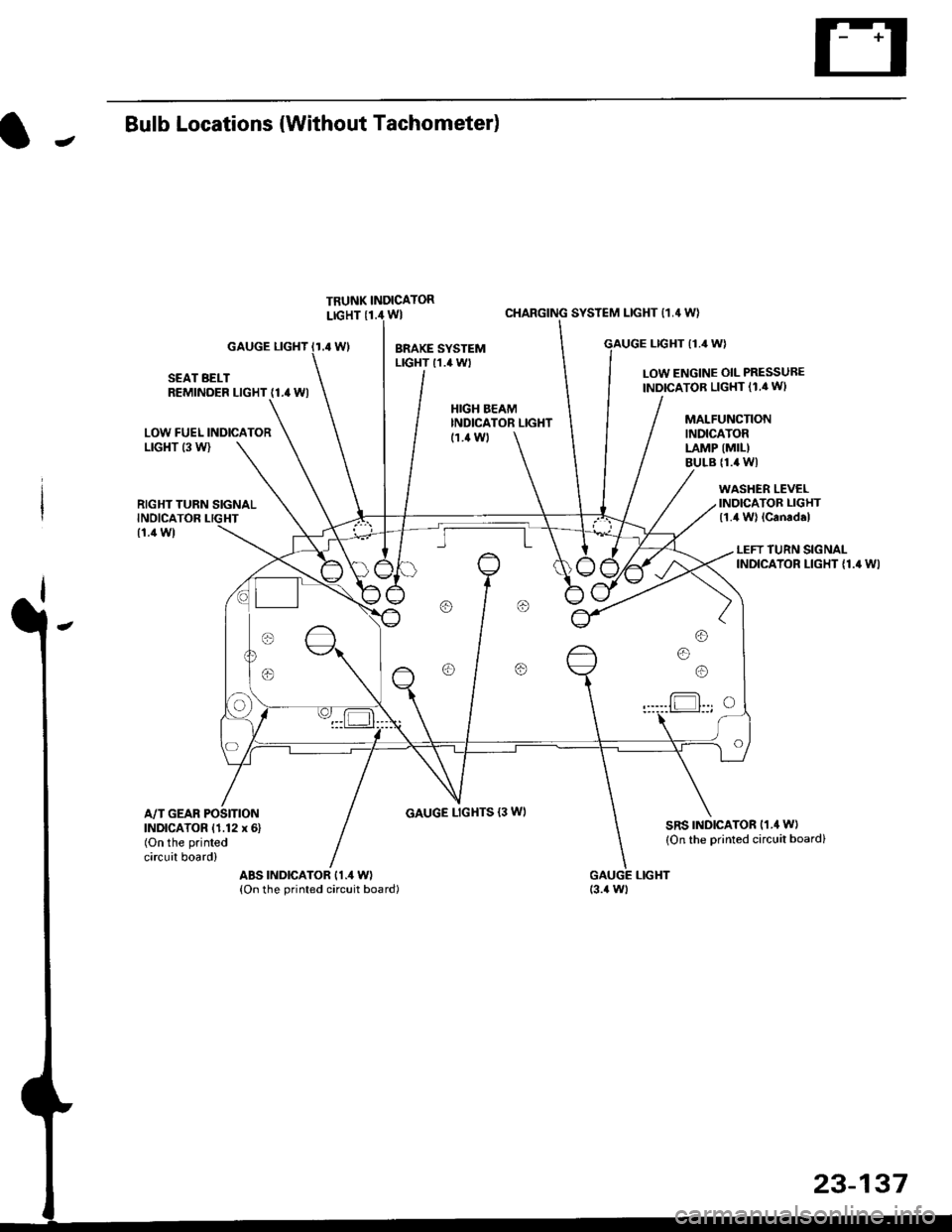
JBulb Locations {Without Tachometer)
TRUNK INDICATORLIGHT {1.i1W}
.4 Wl
CHARGING SYSTEM LIGHT 11,4 W}
LTGHT (1.4 W)GAUGE LIGHT
SEAT BELTREMINDER LIGHT (1.4 WI
LOW ENGINE OIL PRESSUBE
INDICATOB LIGHT (1.4 WI
LOW FUEL INDICATORLrGl{T (3 W)
RIGHT TURN SIGNALINOICATOR LIGHT
(1.1Wt
GAUGE LIGHTS {3 WI
WASHER LEVELINDICATOR LIGHT{1.4 W} lcanad.l
HIGH BEAMINDICATOR LIGHTMALFUNCTIONINDICATORLAMP (MIL)
BULB {1.4 WI
{1.ilW)
LEFT TURN SIGNALINDICATOR LIGHT {1.4 WI
A/T GEAR POSITIONINDICATOR (1.12 x 6)(On the printed
circuit board)
sRs TND|CATOR 11.4 W)
{On the Drinted circuit board}
aBs tNDtcAToR t1.4 W)(On the printed circuit board)(3.{ Wt
o/ o \7 o
23-137
Page 1635 of 2189
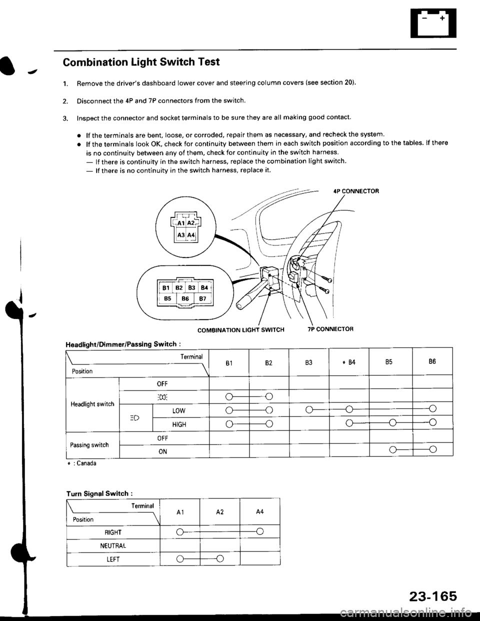
Combination Light Switch Test
1.Remove the driver's dashboard lower cover and steering column covers (see section 20)
Disconnect the 4P and 7P connectors from the switch.
Inspect the connector and socket terminals to be sure they are all making good contact
. lf the terminals are bent, loose. or corroded, repair them as necessary, and recheck the system.
. lf theterminals look OK, check for continuity between them ineach switch position according tothetables lfthere
is no continuity between any of them. check for continuity in the switch harness
- lf there is continuity in the switch harness. replace the combination light switch
- lf there is no continuity in the switch harness, replace it.
2.
4P CONNECTOR
COMBINATION LIGHT SWITCH7P CONNECTOR
HsadlighUDimmer/Passing Switch :
* : Canada
rrr r-l
l(rr mf ItffiTI A3 A11l
Terminal
Position
B182B3*84B586
Headlight switch
OFF
o---o
LOWo---oo-----o
HIGHo-----oo---o
Passing switchOFF
ONo-----o
Turn Signal Switch :
Teminal
;',*;----__\A1A2A4
RIGHToo
NEUTRAL
LEFToo
23-165
Page 1638 of 2189
Headlights
Adjustment
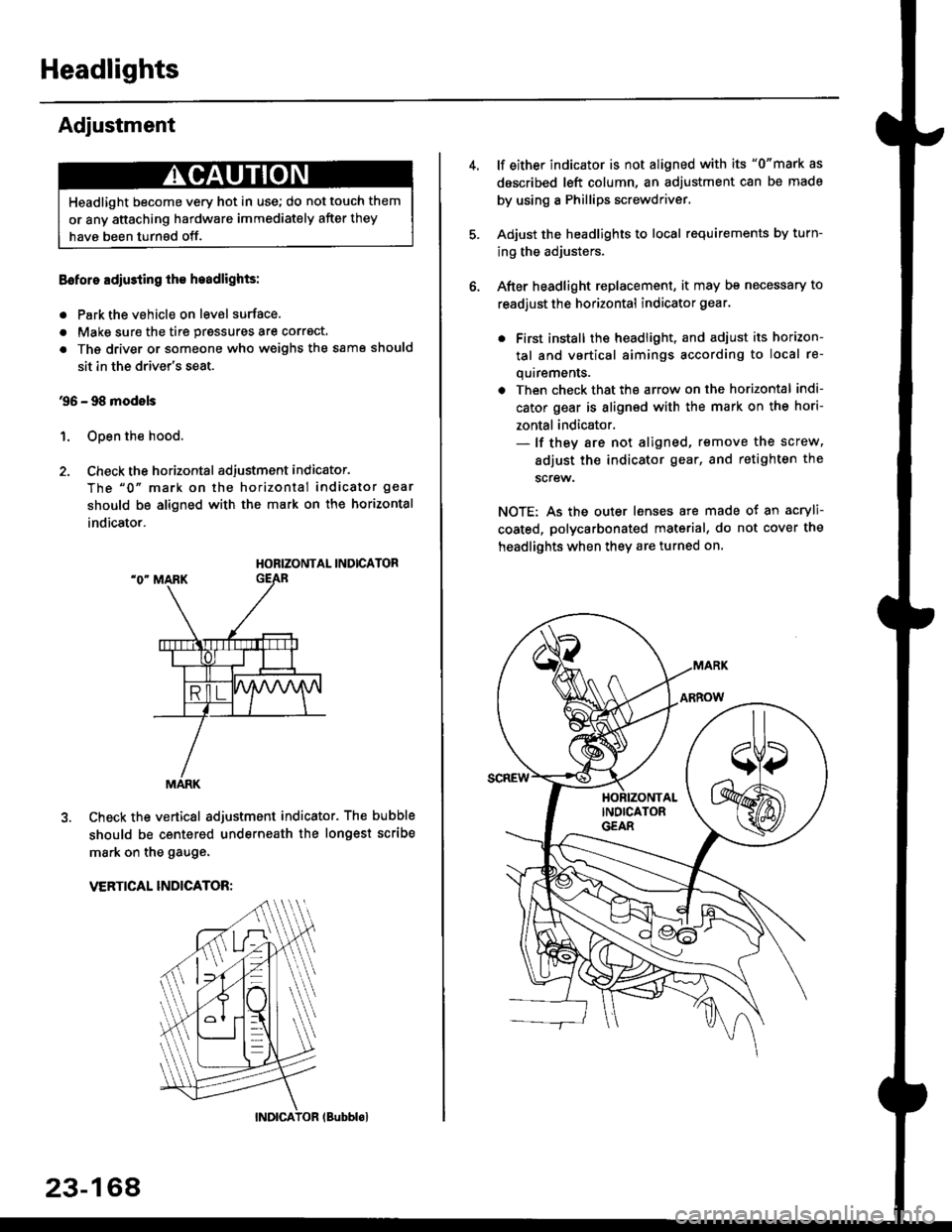
Eoforo adiu3ting th€ h.adlights:
. Park the vehicle on level surface.
. Make sure the tire prgssures are correct.
a The driver or someone who weighs the same should
sit in the driver's seat.
96 - 98 modols
1. Open the hood.
2. Check the horizontal adjustment indicator.
The "0" mark on the horizontal indicator gear
should be aligned with the mark on the horizontal
indicator.
HORIZONTAL INDICATOR
Check the vertical adjustment indicator. The bubble
should be centered underneath the longest scribe
mark on the gauge.
VERTICAL INDICATOR:
Headlight become very hot in use; do not touch them
or any attaching hardware immediately after they
have been turnsd off.
MARK
23-164
(Bubblol
lf either indicator is not aligned with its "0"mark as
described left column, an adjustment can be made
by using a Phillips screwdriver.
Adjust the headlights to local requirements by turn-
ing the adjusters.
After headlight replacement, it may bs necessary to
readjust the horizontal indicator gear.
. First install the headlioht, and adjust its horizon-
tal and vertical aimings according to local re-
quirements.
. Then check that the arrow on the horizontal indi-
cator gear is aligned with the mark on the hori-
zontal indicator.- lf they are not aligned, remove the screw,
adiust the indicator gear, and retighten the
screw.
NOTE: As the outer lenses are made ot an acryli-
coated, polycarbonated material, do not cover the
headlights when they are turned on.
Page 1644 of 2189
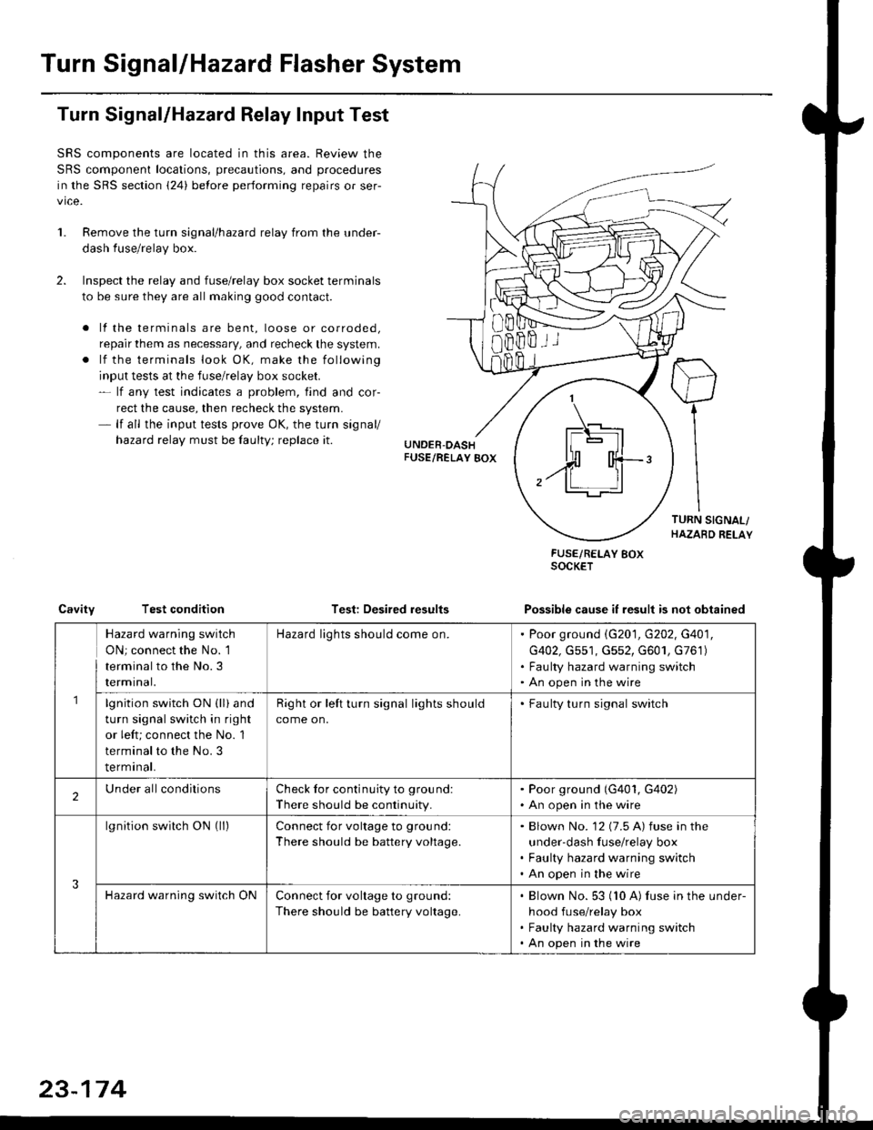
Turn SignallHazard Flasher System
1.
Turn Signal/Hazard Relay Input Test
SRS components are located in this area. Review the
SRS component locations, precautions, and procedures
in the SRS section {24} before performing repairs or ser-
vice.
Remove the turn signal/hazard relay from the under-
dash fuse/relay box.
Inspect the relay and fuse/relay box socket terminals
to be sure they are all making good contact.
. lf the terminals are bent, loose or corroded,
repair them as necessary, and recheck the system.
. lf the terminals look OK, make the following
input tests at the fuse/relay box socket.- lf any test indicates a problem, find and cor-
rect the cause, then recheck the system.- lf all the input tests prove OK, the turn signal/
hazard relay must be faulty; replace it.
Test: Desired results
FUSE/RELAY BOXSOCKET
Possible cause it result is not obtainedCavityTest condition
8Bffii
\_t-E rl.]l
| - lll
n'rl
,.ff T-'t:
Hazard warning switch
ON; connect the No. 1
terminal to the No.3
rermtnat.
Hazard lights should come on.Poor ground \G201, G202, G401,
G402, Gs51, G552, G601, G761)
Faulty hazard warning switch
An open in the wire
lgnition switch ON (ll) and
turn signal switch in right
or left; connect the No. 1
terminal to the No. 3
terminal.
Right or left turn signal lights should
come on.
. Faulty turn signal switch
2Under allconditionsCheck for continuity to ground:
There should be continuity.
. Poor ground (G401, G402). An open in the wire
3
lgnition switch ON (ll)Connect for voltage to ground:
There should be battery voltage.
Blown No. '12 (7.5 A) fuse in the
under-dash fuse/relay box
Faulty hazard warning switch
An open in the wire
Hazard warning switch ONConnect for voltage to ground:
There should be battery voltage.
Blown No. 53 (10 A) fuse in the under-
hood fuse/relay box
Faulty hazard warning switch
An open in the wire
23-174
Page 1679 of 2189
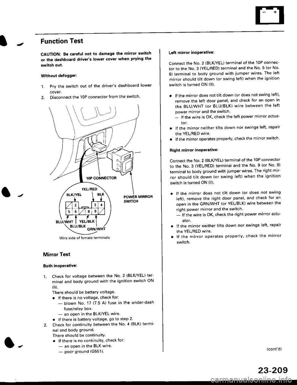
Function Test
CAUTION: Be careful not to damage the mirror switch
or the dashboard drivel's lower covel when prying the
swhch out.
Withoui defogger:
1. Pry the switch out of the driver's dashboard lower
cover.
2. Disconnect the 10P connector from the switch.
lOP CONNECTOR
BLU/WHT
YEL/RED
BLK/YELBLK
4
568
YEL/BLK
POWER MIRRORswtTcH
\:/"*jgil*-(
Wire side of female termanals
Mirror Test
Both inoperative:
1. check for voltage between the No. 2 (BLVYEL) ter
minal and body ground with the ignition switch ON
0 r).
There should be batterY voltage
. If there is no voltage, check for:
- blown No. 17 (7 5 A) fuse in the under-dash
tuse/relay box- an open in the BLK'/YEL wire.
o lf there is battery voltage, go to step 2.
2. Check for continuity between the No 4 (BLK) termi-
nal and body ground.
There should be continuity.
. lf there is no continuity, check for:
- an open in the BLK wire.
- poor ground (G551).
Left mirror inoporalive:
connect the No. 2 {BLK/YEL) terminal of the 10P connec-
tor to the No. 3 (YEURED) terminal and the No 5 (or No
6) terminal to body ground with jumper wires The left
mirror should tilt down (or swing left) when the ignition
switch is turned ON (ll)
. lf the mirror does not tilt down (or does not swing left),
remove the left door panel. and check for an open in
the BLU/WHT (or BLU/BLK) wire between the left
power mirror and the switch
- lf the wire is OK. check the left power mirror actua-
tor.
lf the mirror neither tilts down nor swings left. repair
the YEURED wire.
lf the mirror operates properly, check the mirror switch'
Right mirror inoperative:
Connect the No. 2 (BLK /EL) terminal of the 10P connector
to the No. 3 (YEURED) terminal and the No. 9 (or No 8)
terminal to body ground with jumper wires The right mir-
ror should tilt down (or swing left) when the ignition
switch is turned ON (ll).
. lf the mirror does not tilt down (or does not swlng
left), remove the right door panel. and check for an
open in the GRN/WHT (or YEUBLK) wire between the
right power mirror and the switch.
- lf the wire is OK, check the right power marror actu-
ator.
. lf the mirror neither tilts down nor swings left. repair
the YEURED wire
. lf the mirror operates properly, check the mirror
switch.
(cont'd)
23-209
Page 1701 of 2189
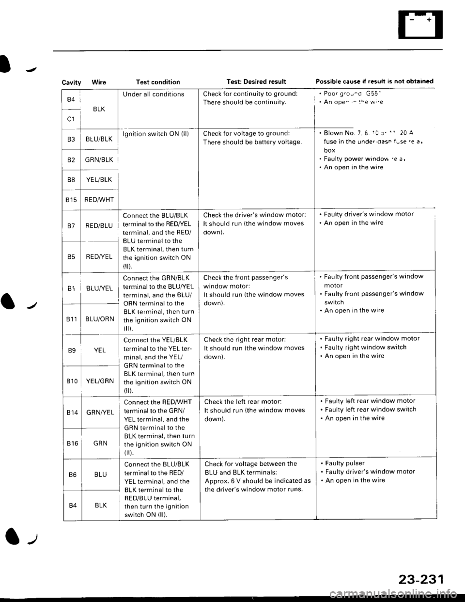
CavityWireTest conditionTest: Desired resultPossible caus! d r"suh rs nol obtrincd
to:
c1
BLK
UnderallconditionsCheck for continuity to groundl
There should be continuity., An ope^ ^ :he tt .e
. Blown No.7.6 10 r' " 20 A
fuse in the unde. oast f.se 'e a,
box. Faulty power windo$ 'e a,. An open in the wire
B3BLU/BLKlgnition switch ON (ll)Check for voltage to grou nd:
There should be battery voltage.
B2GRN/BLK
YE L/BLK
R EDA/VHT815
81RED/BLU
RED/YEL
Connect the BLU/BLK
terminal to the RED/YEL
terminal, and the RED/
BLU terminal to the
BLK terminal, then turn
the ignition switch ON
1I i.
Check the driver's window motorl
It should run (the window moves
oown).
. Faulty driver's window motor
. An open in the wire
B1BLUIVEL
Connect the GRN/BLK
terminal to the BLU|YEL
terminal, and the BLU/
Check the front passenger's
wrnoow motor:
It should run (the window moves
Fau lty front passenger's window
motor
Faulty front passenger's window
An open in the wire
811BLU/ORNBLK terminal, then turn
the ignition switch ON
0 r).
B9YEL
connect the YEL/BLK
terminal to the YEL ter-
minal, and the YEU
GRN terminal to the
BLK terminal, then turn
the ignition switch ON
0 r).
Check the right rear motor:
It should run (the window moves
down).
Fauity right rear window motor
Fau lty right window switch
An open in the wire
Bt0YEUGRN
814GRNI/EL
connect the RED,ryVHT
terminal to the GRN/
YEL terminal, and the
GRN terminal to the
BLK terminal, then turn
the ignition switch ON
0 r).
Check the left rear motor:
It should run (the window moves
Faulty left rear window motor
Faulty left rear window switch
An open in the wire
816GRN
B6BLU
Connect the BLU/BLK
terminal to the RED/
YEL terminal, and the
BLK terminal to the
RED/BLU terminal,
then turn the ignition
switch ON (ll).
Check for voltage between the
BLU and BLK terminalsl
Approx. 6 V should be indicated as
the driver's window motor runs.
Faulty pulser
Faulty driver's window motor
An open in the wire
B4BLK
23-231
Page 1753 of 2189
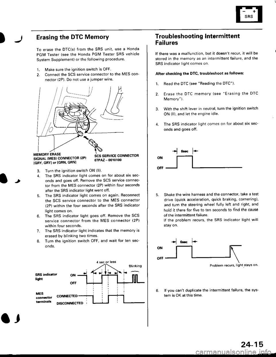
)Erasing the DTC Memory
To erase the DTC(s) from the SRS unit, use a Honda
PGM Tester (see the Honda PGM Tester SRS vehicle
System Supplement) or the following procedure
1. Make sure the ignition switch is OFF
2. Connect the SCS service connector to the MES con-
nector (2P). Do not use a jumper wlre.
]P,
&
.!--J
MEMORY ERASE
SIGNAL (MESI CONNECTOR I2PI
IGRY, GRYI or [GRN, GRNI
SCS SERVICE CONNECTORo?PAZ - 0010100
t
7.
Turn the ignition switch ON (ll).
The SRS indicator light comes on for about six sec-
onds and goes off. Remove the SCS service connec-
tor from the MES connector (2P) within four seconds
after the SRS indicator light went off.
The SRS indicator light comes on again. Reconnect
the SCS service connector to the lvlES connector
(2P) within the four seconds after the SRS indicator
light comes on.
The SRS indicator light goes off. Remove the SCS
service connector from the MES connector (2P)
within four seconds.
The SRS indicator light indicates that the memory is
erased by blinking two times.
Turn the ignition switch OFF, and wait for ten sec-
onos.
8.
SRS indictlorlighi
MESconncclottcaminals
CONNECTED
O,
DISCONI{ECTED
24-15
Troubleshooting Intermittent
Failures
lf there was a malfunction, but it doesn't recur, it will be
stored in the memory as an intermittent failure, and the
SRS indicator light comes on.
Afte. checking the DTC, troubleshoot as lollows:
1. Read rhe DTC {see "Reading the DTC"}.
Erase the DTC memory (see "Erasing the DTC
Memory").
With the shifi lever in neutral, turn the ignition switch
ON (ll), and lei the engine idle.
The SRS indicator light comes on for about six sec-
onds and goes off.
l*F
ON
tl-- -l
Shake the wire harness and the connector, take a test
drive (quick acceleration, quick braking, cornering),
and turn the steering wheel fully left and right, and
hold it there for five lo ten seconds to find the cause
of the intermittent failure.
lf the problem recurs, the SRS indicator light will
stay on.
-q 6a.c f'-
:q
Problem recurs, light stays on
3.
4.
6.lf vou can't duplicate the intermittent failure, the sys-
tem is OK at this time.