Page 1189 of 2189
Rear Drum Brake
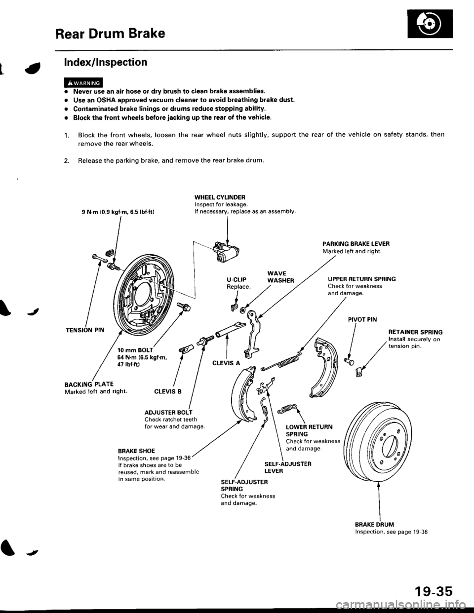
Index/lnspection
'1.
a
a
Never use an air hose or dly brush to clean brake assemblies,
Use an OSHA approved vacuum cleanar to avoid breathing brake dust,
Contaminated brake linings or drums reduce stopping ability.
Block the tront wheels before iacking up ths r€ar of lhe vehicle.
Block the front wheels, loosen the rear wheel nuts slightly, support the rear of the vehicle on safety stands, then
remove the rear wheels.
2. Release the parking brake, and remove the rear brake drum.
I N m 10.9 kgtm, 6.5 lbf.ftl
TENSION PIN
10 mm BOLT6,1N m 15.5 kgf m,47 tbf.ft)
WHEEL CYLINDERInspect for leakage.lf necessary, replace as an assembly.
u-cLrPReplace.
WAVEWASHER
PARKING BRAKE LEVERMarked left and right.
Check for weaknessano oamage,
UPPER RETURN SPRING
I
@JPIVOT PIN
BACKING PLATEMarked lelt and right-
/
€f-l.^
I I
*'t")
ctEv'sB
/ (t
/ ,.ro,".r r.*,"n
/ , Install securely on
| / tension pin.
d"/
IU
ADJUSTER BOI-TCheck ratchet teethfor wear and damage.LOWER RETURNSPRINGCheck for weaknessand oamage.BRAKE SHOEInspection, see page 19-36lf brake shoes are to bereused, mark and reassemblein same position.
SELF.ADJUSTERLEVEB
SELF-ADJUSTERSPRINGCheck for weaknessano oamage.
BRAKE DRUMInspection, see page '19 36
t
19-35
Page 1205 of 2189
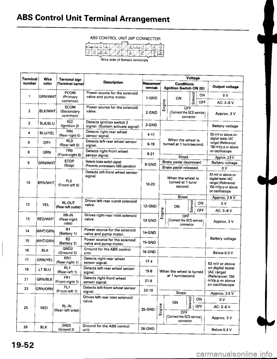
ABS Control Unit Terminal Arrangement
ABS CONTROL UNIT 26P CONNECTOR
Wire side of temale terminals
Terminalnumo0rWirecolorTerminal signTerminalnamoDgscriptionVoltage
Conditions(lgnition Switch ON flt))Output voltagoteminals
PCOM(Primary
common)
Power source for the solenoidvalve and pump motor.1-GNDON
=ONOV
AC: 3-6 V
BLK/WHTscoM(Secondary
common)
Power source for the solenoid
2.GNDOFF
lConnect the SCS service\
conneclor lApprox. 3 V
ELVBLUtG2(lgnition 2)Detects ignition switch 2
!9nal. (system activate signal)3-GNDBatt€ry voltage
BLU/YELRRO(Rear-right 0)Detects right-rear wheelsensor signal.4-17
When the wheel isturned at 1 turn/second.
53 mV or above ondigitaltester (ACra nge) {Fefera nce)150 mvp-p or aboveon oscilloscope
6GRYRLO(Rear-left 0)Detects left-rear wheel sensorsrgnal.6-19
8GRNFRO(Front-right 0)D€tects right-front wheelsgnsor srgnal,a-21StopsApprox.2.5VSTOP(Stop)hects brake switch signal.(Prevents unnecess€ry ABS operation)9-GNDBrake pedal depressed.Battery voltage
Brake pedal released.OV
10BRN^/vHTFLO(Front-left 0)
Detects left-front wheel sensorsignal.
10-23
When the wheel isturned at 1 turn/secono.
53 mV or above ondigitaltester (ACrange) (Referance)
150 mVFporaboveon oscilloscope
9!opsApprox. 2.5 V
12YELRLOUT(Rearjeft outlet)
Drives left-rear outlet solenoid
12.GNDON-9ONOV
OFFAC: 3^6 V
REDMHTRR]N(Rear-right
inlet)
Drives right-rear inlet solenoidvalve.13-GNDOFF
lconnect the SCS service]i connector IApprox. 3 V
14B1(Battery 1)Power source for the solenoidvatve and pump motor.14.GND
Battery voltage15WHT/G R N82(Baftery 2)Power source for the solenoidvarve ano pump motor.15.GND
r6BLKGND2{Ground 2)Ground for the ABS controlunit.16-GNDBelow 0.3 V
17GRN/'/ELRR1(Rear-right 1)Detects right-rear wheelsensor signal.17-4
When the wheel is turnedat 1 turn/second.
53 mV or aboveon digitaltester(AC range)(Referance) 150mVp-p or aboveon oscilloscope
19LT BLURLl(Rea.-left 1)Detects left-rear wheel sensorsagnal.19-6
GRN/BLKFRl(Front-right 1)Detects right-front wheelsensor signal.21-8
FL1(Front-left 1)Detects left-front wheel sensorsignal.23-10StopsApprox. 2.5 V
REDRL-IN(Rear-lett inletl
Drives left-r€ar inlet solenoid
25.GND
ut
ON
'6
-9ONOV
OFFAC: 3-6 V
OFF
lconnect the SCS service] connector lApprox. 3 V
BLKGND3(Ground 3)Ground for the ABS cgntrolunit.26.GNDBelow 0.3 V
19-52
Page 1217 of 2189
Troubleshooting
Wheel Sensor
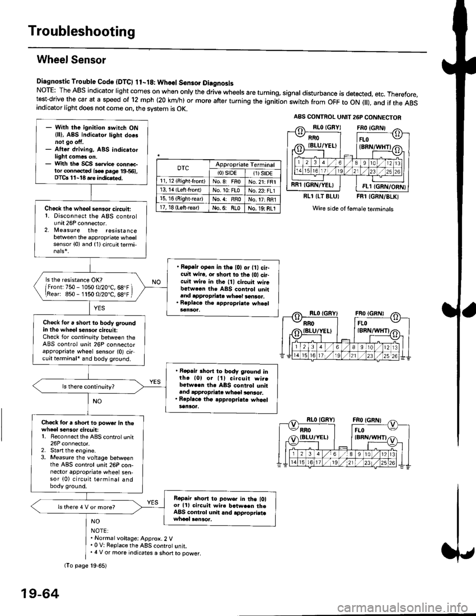
Diagnostic Trouble Gode {DTC) ll-18: Wheol S€n3ol DiagnosisNoTE: The ABS indicator light comes on when only the drive wheels are turning, signal disturbance is detected, etc. Therefore,test-drive the car at a speed of 12 mph (20 krn/h) or more after turning the ignition:witch from OFF to ON fll), and if the ABSindicator light does not come on, the svstem is OK.
0TcAppropriate Terminal(0)srDE11) SrD€r 1, 12 (Right-front)No.8: FRoNo.21: FRI13, 14 (Left-front)No. 10: FLoNo.23: FL115, 16 {Right-rear)No. {: RRoNo. 17: RRl17, 18 (Left-rear)No.6: RLoNo. 19: RLI
RLl (LT BLU}FRl (GRN/BLKI
Wire side ol female terminals
NO
NOTE:. Normal voltage: Approx.2 V' 0 V: Replace the ABS controt unit.. 4 V or more indicates a short to power.
A8S CONTROL UNIT 26P CONNECTOR
RRO
IBLU/YELI
RR1 IGRN/YELIFL1 IGRN/ORN}
- With the ignition switch ON{ll), ABS indicator tighr doe.noi go off,- Aftsr driving, ABS indicatotlight comes on.- With the SCS so.vice connac-tor conn€c,ted {soe pege 19-561,DTCs 11-18 a.e indicrted.
Chock lhe wheol sensor ci.cuit:1. Disconnect the ABS controlunit 26P connector.2. lleasure the resistancebetween the appropriate wheelsensor (0) and (1) circuit termi,
. Reprir op€n in the l0l or {0 cir-cuit wiro, or shon to thc {01 cir-cuit wi.o in thc {11 circuit wircbctween ths ABS control unitand approprieto wheel a6nsor.. R.pl.ce th€ epp.opri.te wheal3€nloa.
ls the resistance OK?
/Frontr 750 - 1050 o/20"C, 68.F \\Rear: 850- 1150 O/20.C, 68"F /
Check toru short to body groundin the wheel senso. circuit:Check for continuity between theABS control unit 26P connectorappropriate wheel sensor (0) circuit terminali and body ground.
. Rapair short to body ground inth6 (0) or lll cilcuit wi..bctwa.n th6 ABS control unitand appropdaie whoel lonsor.. Rep|'c6 tho appropriatc whcelsanlor.
Chock tor a sho.t to powe. in thowheel3en3or circuit:1. Reconnect the ABS control unit26P connector,2. Start the engine.3. Measure the voltage betweenthe ABS control unit 26P con-nector appropriate wheel sen-sor (0) circuit terminal andbody ground.
Ropair rhon to powo. in the l0lor lll circuit wire batw.en th€ABS cont.ol unit and .pplopriatawhccl !€naoa,
ls there 4 V or more?
fio page 19-65)
19-64
Page 1326 of 2189
Hood
Adjustment
NOTE: Before adjusting the hood, loosen each bolt slightly.
1. Adjust the hood hinges right and left, as well as fore and aft, by using the elongated holes.
2. Turn the hood edge cushions, as necessary. to make the hood fit flush with the body at front and side edges.
3, Adjust the hood latch to obtain the proper height at the forward edge.
4. After adjustment, tighten each bolt securely.
6x1.0mm9.8 N.m {1.0 kgt.m,7.2 tbt.tll
NOTE: Move the hood latch right or left
is centered in the hood latch as shown.
)
until the striker
6x1.0mm9.8 N.m {1.0 kgf.m,7.2 tbf.ftl
\
20-96
Page 1327 of 2189
Trunk Lid
Adjustment
NOTE; Before adjusting the trunk lid, loosen each bolt slightly.
1. Adjust the trunk lid hinges right and left, as well as fore and aft, by using the elongated holes'
2. Turn the trunk lid edge cushions, as necessary, to make the trunk lid fit flush with the body at the rear and side edges.
3. Adiust the fit between the trunk lid and the trunk lid opening by moving the striker'
4. After adjustment, tighten each bolt securely
TRUNK LIO EDGE
CUSHION
TRUNK LID
NOTE: Take care notto hit the rear windowwhen loosening thebolts.
NOTE: Move the striker right or left until it's centered in
the trunk lid latch as shown.
TRUNK LIO
9.8 N.m {1.0 kgf.m,7 .2lbl.ltlSTRIKER
20-97
Page 1328 of 2189
Hatch
Adjustment
NOTE:
. Before adjusting the hatch, loosen each bolt and nut slightly.
a The suDport struts should be removed.
. To adjust, remove both hatch sidetrim (see page 20-63) and the rear roof trim (see page 20-65).
1. Adjust the hatch hinges right and left, as well as fore and aft. by using the elongated holes
2. Turn the hatch edge cushions, as necessary, to make the hatch fit flush with the body at each side.
3. Adjust the hatch fit to the hatch opening by moving the striker.
4. After adiustment, tighten each bolt and nut securely.
6x1.0mm9.8 N.m (1.0 kgf.m,
HATCHEDGE CUSHION
HATCHHINGERearward
HAEDGECUSHION
j ... 22
\,_1q
N.m (2.2 kgf.m,tbf.ftl
\
co
38Nm(3.9kgfm,2.8 rbf.ft)
NOTE: Move the striker right or left until it's centered in
the hatch latch. as shown.
HATCHHINGESTRIKER
l0x1VER
HATCHEDGECUSHION
9.8 N.m 11.0 kst.m,7.2 tbf.ft)HATCHLATCH
20-98
6x1.0mm
Page 1342 of 2189
Opener and Latch
Replacement (cont'd)
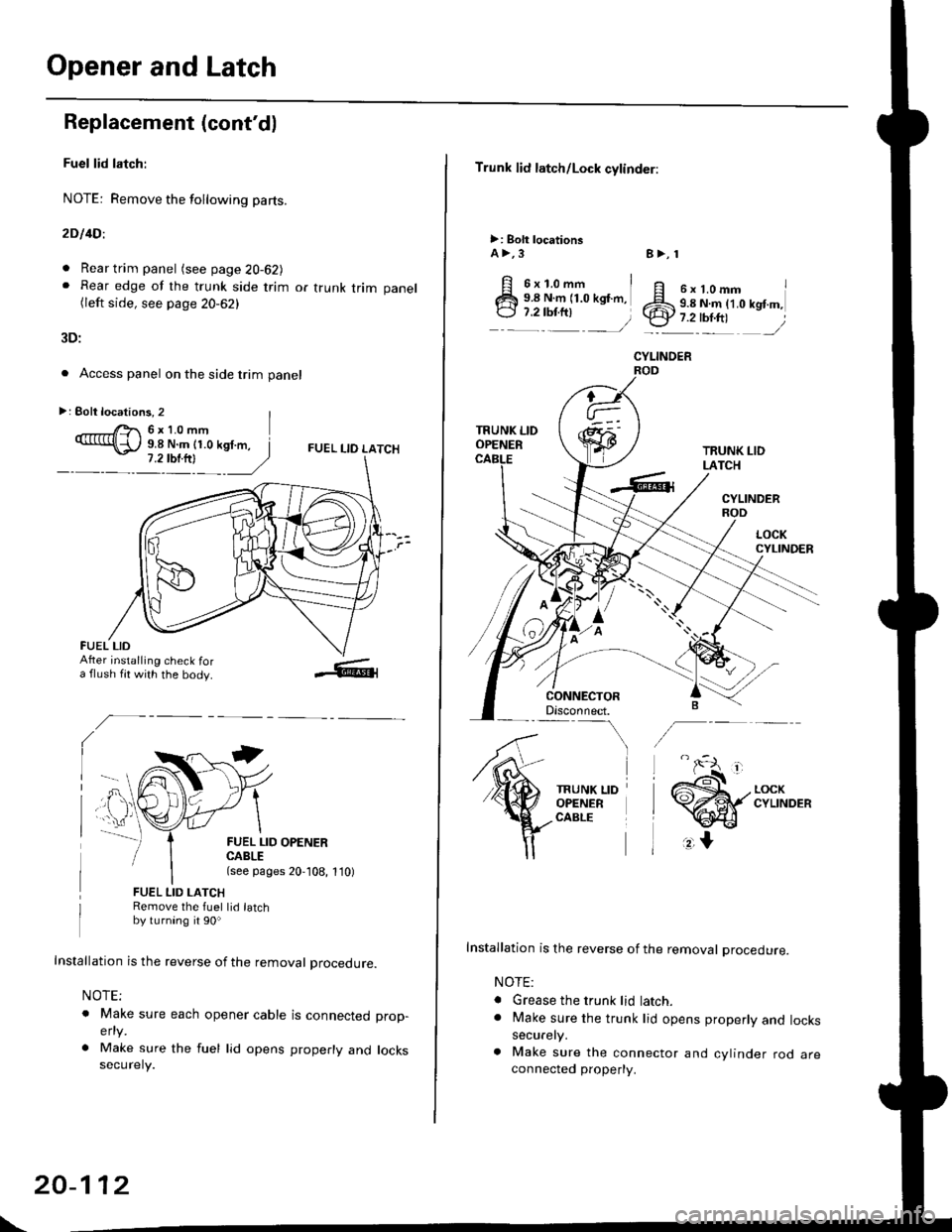
Fuel lid latch:
NOTE: Remove the following pa(s.
2D l4Dl
. Rear trim panel (see page 20-62J. Rear edge of the trunk side trim or trunk trim panel(left side, see page 20-62)
3D:
. Access panel on the side trim panel
FUEL I-IO LATCH
II
FUEL LID OPENERCABLE(see pages 20,108, 1'10)
FUEL LID LATCHRemove the fuel lid latchby turning it 90o
Installation is the reverse of the removal procedure.
NOTE;
o Make sure each opener cable is connectedelty
. Make sure the fuel lid opens properly andsecurely.
prop-
locks
>: Eolt locations, 2 |r'- 6x10mm9.8 N.m (1.0 kgf.m, I
FUEL LIDAfter installing check fora flush fit with the body.
\
20-112
Trunk lid latch/Lock cylinder:
>: Bolt locationsA >,3
6x1.omm i9.8 N.m (1.0 kgf.m,
:::^ _=)
TRUNK LIDOPENER
CONNECTORDisconnect.-\
TRUNK LIDOPENERCABLE
8>, 1
ff e rt.omm IZS 9.8 N.ln (1.0 kgt m,.ty 7.2-tbr.ftt ,/
CYLINOER
TRUNK LIDLATCH
CYLINDERROD
Installation is the reverse of the removal procedure.
NOTE:
. Grease the trunk lid latch.. Make sure the trunk lid opens properly and lockssecurely.
a Make sure the connector and cylinder rod areconnected property.
Page 1455 of 2189
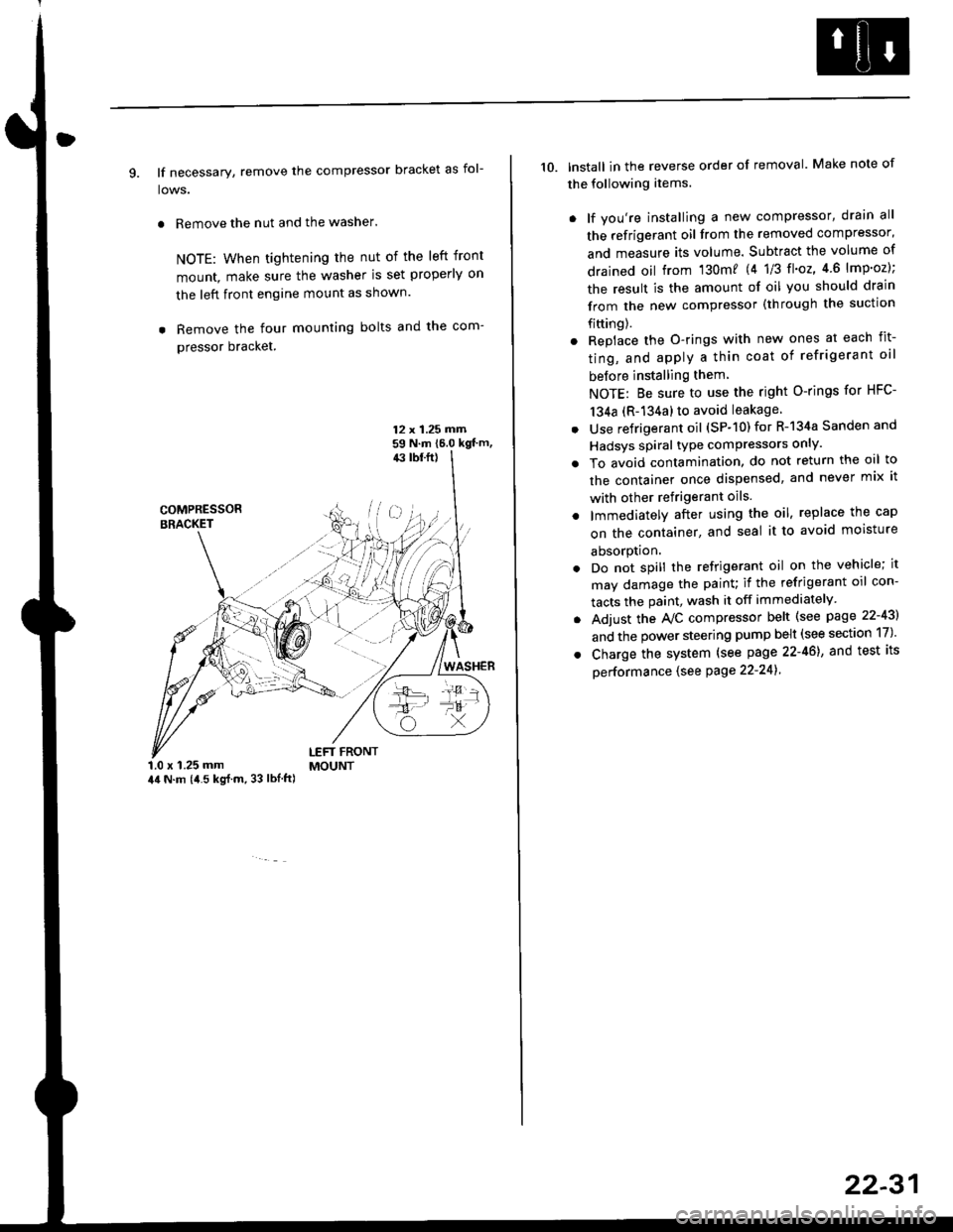
9. lf necessary, remove the compressor bracket as fol-
lows.
. Remove the nut and the washer.
NOTE: When tightening the nut of the left front
mount, make sure the washer is set properly on
the left front engine mount as shown.
. Remove the four mounting bolts and the com-
pressor bracket.
12 x 1.25 rrirn59 N.m 16.0 kgt'm,43 tbf.ft)
COMPRESSORBRACKET
WASHER
1.0 x 1.25 mm44 N.m (i1.5 kg{.m, 33 lbl.ft)
LEFT FRONTMOUNT
10. lnstall in the reverse order of removal. Make note of
the following items.
. lf you're installing a new compressor, drain all
the refrigerant oil from the removed compressor,
and measure its volume. Subtract the volume of
drained oil from '130m? 14 1/3 tl'o2,4 6 lmp'oz);
the result is the amount of oil you should drain
from the new compressor (through the suction
fifting).
. Replace the O-rings with new ones at each fit-
ting, and apply a thin coat of refrigerant oil
before installing them
NOTE: Be sure to use the right O-rings for HFC-
134a (R-134a) to avoid leakage
. Use refrigerant oil (SP-10) for R-134a Sanden and
Hadsys spiral type compressors only'
o To avoid contamination, do not return the oil to
the container once dispensed, and never mix it
with other refrigerant oils.
. lmmediatelY after using the oil, replace the cap
on the container, and seal it to avoid moisture
absorption.
. Do not spill the refrigerant oil on the vehicle; it
may damage the painu if the refrigerant oil con-
tacts the paint, wash it off immediately
. Adjust the Ay'C compressor belt (see page 22-43)
and the power steering pump belt (see section 17)'
. Charge the system (see page 22-46), and test its
oerformance (see Page 22-241
22-31