Page 906 of 2189

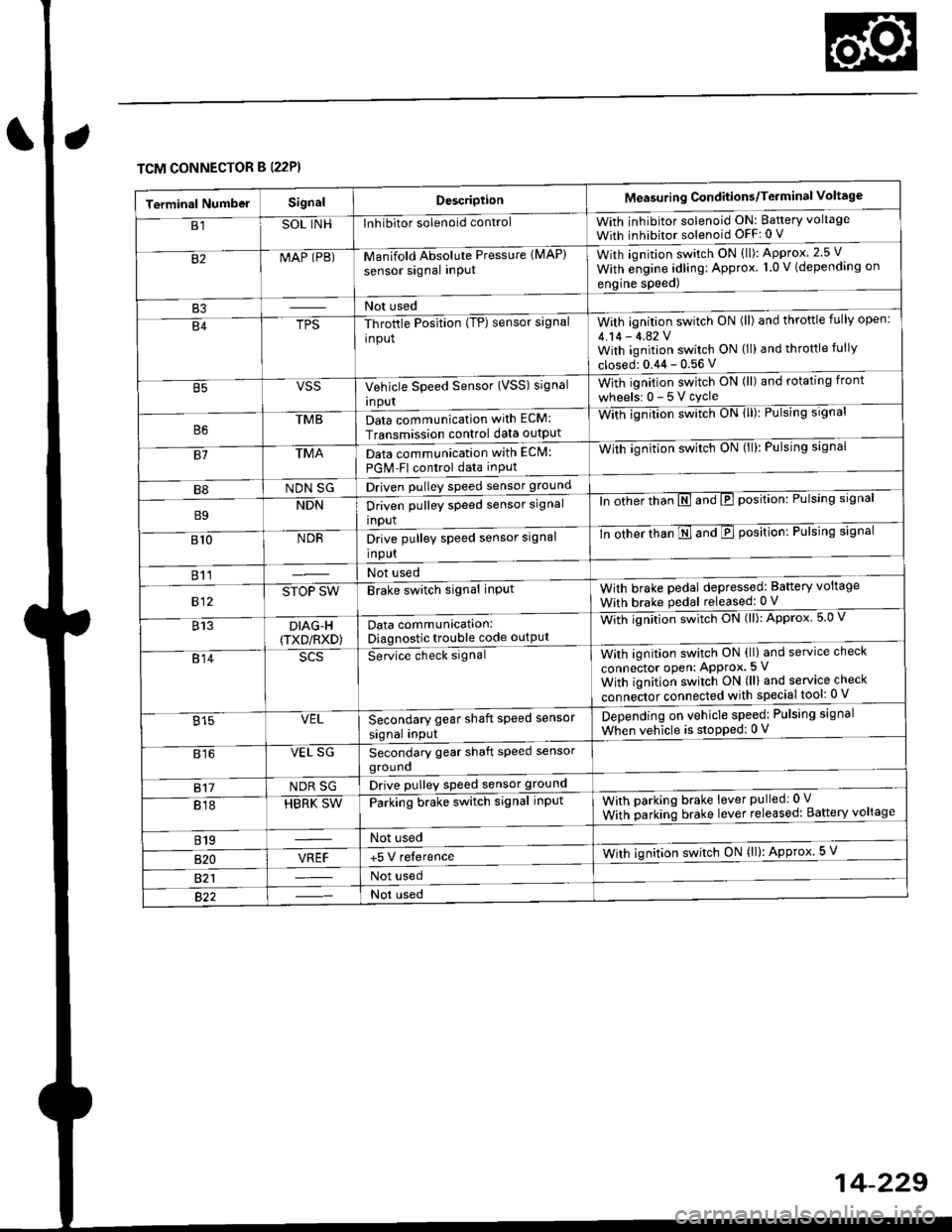
TCM CONNECTOR B (22P}
Terminal NumbelSignalDescriptionMeasuring Conditions/Terminal Voltage
B1SOL INHInhibitor solenoid controlWith inhibitor solenoid ON: Baftery voltage
With inhibitor solenoid OFF: 0 V
82MAP (PB)-M an if old Absol r-rte Pressure IMAP)
sensor signal inPUtWith iqnition switch ON (ll): Approx.2.5 V
With e;gine adling: Approx. 1.0 V (depending on
engine speed)
B3Not used
B4TPS-Throttle Position (TP) sensor signal
input
With ignition switch ON (ll) and throftle fully open:
4.14 - 4.42 VWith ignition switch ON (ll) and throttle fully
closed: 0.44 - 0.56 V
VSSVehicle Speed Sensor (VSS) signal
Inpur
With ignition switch ON (ll) and rotating front
wheelsr 0-5Vcycle
TMBData communication with ECM:
Transmission control data outpUt
With ignilion swltch UN lll): rulslng slgnar
81TMAData communication with EClvl:
PGM Fl control data inPut
With ignition swltch uN {ll,: l-ulslng slgnal
B8NDN SGDriven pulley speed sensor ground
B9NDNDriven pulley speed sensor signal
input
ln other thTnE and E position: Pulsing signal
810NDRDrive pulley speed sensor signal
Input
-tn ottrer ttran E ana E position: Pulsing signal
811Not used
812STOP SWBrake switch signal inPutWith brake pedal depressed: Battery voltage
With brake pedal released: 0 V
813DIAG-H(TXD/RXD)Data communication:Diagnostic trouble code outPut
Wittr ignitio.r s*itct' ON (ll): Approx 5.0 V
814Se-ice ctrect signatWith ignition switch ON (ll) and service check
connector oPen: APProx.5 V
With iqnition switch ON (ll) and service check
"onn"itot. connect"d with special tool: 0 V
Secondary gear shaft speed sensor
signal input
Depending on vehicle speed: Pulsing signal
When vehicle is stoPped: 0 V815VEL
816VEL SGSecondary gear shaft speed sensorgrouno
817NDR SGDrive pulley speed sensor ground
818HBRK SWParking brake switch signal inPutWith parking brake lever pulledr 0 V
With parking brake lever released: Battery voltage
819Not used
B�20VREF+5 V relerenceWith ignition switch ON (ll): Approx 5 V
821Not used
Not used
Page 909 of 2189

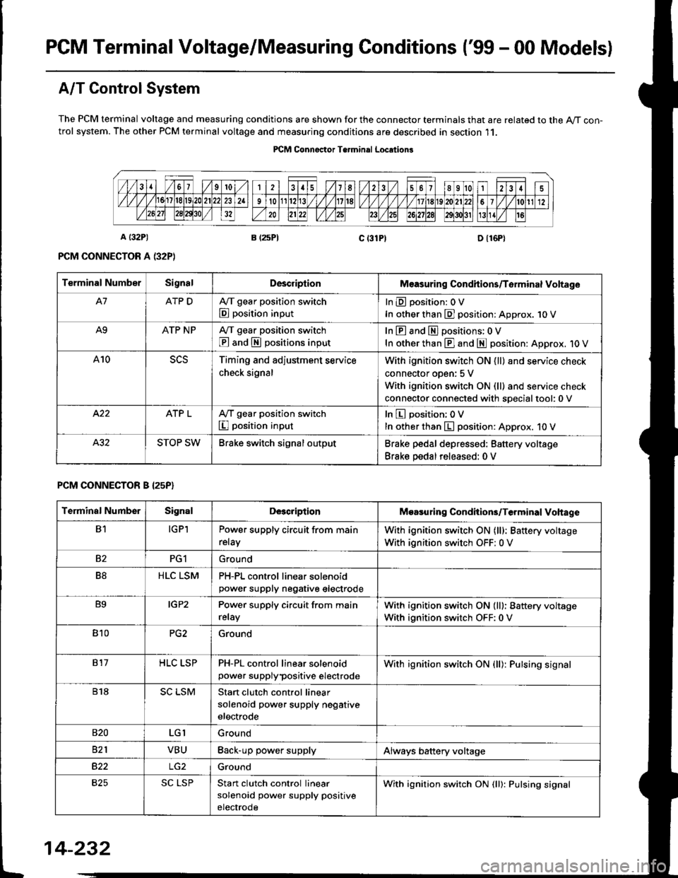
PGM Terminal Voltage/Measuring Conditions ('99 - 00 Modelsl
A/T Control System
The PCM terminal voltage and measuring conditions are shown for the connector terminals that are related to the A/T con-trol system. The other PCM terminal voltage and measuring conditions are described in section 11.
PICM Connoctor Terminrl Location3
Terminal NumberSignalDescriplionMeasuring Condhions/Torminal Voltage
A7ATP DA,/T gear position switch
E position input
InEposition:OV
In other than E] position: Approx. 1O V
A9ATP NPA/T gear position switch
@ and S positions input
In E and El positions: 0 V
In other than E] and E position: Approx. 1O V
A10Timing and adjustment service
check signal
With ignition switch ON {ll} and service check
connector oDen: 5 V
With ignition switch ON (ll) and service check
connector connected with soecialtool:0 v
ATP LA,/T gear position switch
I position input
In E position; OV
In other than E position: Approx. 10 V
STOP SWBrake switch signal outputBrake pedal depressed: Battery voltage
Brake pedal released: 0 V
PCM CONNECTOR B I25P}
Terminal NumberSignalDescriptionMoasuring Condhions/Terminal Vohage
B1IGPlPower supply circuit from main
relay
With ignition switch ON (lll: Battery voltage
With ignition switch OFF: 0 V
82PG1Ground
B8HLC LSMPH-PL control linear solenoidpower supply neqative electrode
B9IGP2Power supply circuit from main
relay
With ignition switch ON (lll: Battery voltage
With ignition switch OFF:0 V
810PG2Ground
817HLC LSPPH-PL control linear solenoid
power supplypositive electrode
With ignition switch ON {ll): Pulsing signal
818SC LSMStart clutch control linear
solenoid power supply negative
electrode
s20LGIGround
821VBUBack-up power supplyAlways battery voltage
B22Ground
825SC LSPStan clutch control linear
solenoid power supply positive
electrode
With ignition switch ON (ll): Pulsing signal
t
14-232
Page 910 of 2189
![HONDA CIVIC 1996 6.G Workshop Manual \a
PCM CONNECTOR D {16P)
14-233
Terminal Numbs]SignalDescriptionMeasuring Conditions/Terminal Voltage
D1VELSecondary gear shaft speed
sensor signal input
Depending on vehicle speed: Pulsing signal
Whe HONDA CIVIC 1996 6.G Workshop Manual \a
PCM CONNECTOR D {16P)
14-233
Terminal Numbs]SignalDescriptionMeasuring Conditions/Terminal Voltage
D1VELSecondary gear shaft speed
sensor signal input
Depending on vehicle speed: Pulsing signal
Whe](/manual-img/13/6068/w960_6068-909.png)
\a
PCM CONNECTOR D {16P)
14-233
Terminal Numbs]SignalDescriptionMeasuring Conditions/Terminal Voltage
D1VELSecondary gear shaft speed
sensor signal input
Depending on vehicle speed: Pulsing signal
When vehicle is stoPPed: APProx. 0 V
02SOL INHlnhibitor solenoid controlWith inhibitor solenoid ON: Battery voltage
With inhibitor solenoid OFF: 0 V
D3SH LSMShift control linear solenoid
power supply negative electrode
D4SH LSPShift control linear solenoid
power supply positive electrode
With ignition switch ON (ll): Pulsing signal
D5VB SOLPower supply for solenoid valvesWith ignition switch ON (ll): Baftery voltage
With ignition switch OFF:0 V
D6ATP RA,/T gear position switch E
position input
InEposition:0V
In other than B position; Approx. 10 V
D]VEL SGSecondary gear shaft sPeed
sensor ground
D8Not used
D9Not used
D10NDNDriven pulley speed sensor signal
anput
In other than E and E position: Pulsing signal
D11NDRDriven pulley speed sensor signal
input
ln other than E and E position: Pulsing signal
D12NDR SGDrive pulley speed sensor ground
D13ATP SA,/T gear position switch E
position input
InE position: 0V
In other than E position: Battery voltage
D14D INDD indicator light controlWhen ignition switch is first turned ON (ll):
Battery voltage for two seconds
In E position: Battery voltage
D15Not used
D16NDN SGDriven pulley speed sensor
grou nd
Page 915 of 2189

Symptom-to-Component Chart
Electrical System -'96 - 98 Models
*: The DTC in parentheses is the code @ indicator light indicates when the Data Link Connector is connected to the HondaPGM Tester.
DTC*O Indicator
LightMILDetection ltemPage
P1790
(3)BlinksONThrottle position sensor14-242
P179'l
(4)BlinksONVehicle speed sensor14-243
P1705
(5)BlinksONAy'T gear position switch (short to groundl't 4-244
P1706
(6)OFFONA/T gear position switch {open)14-246
P0725
(11)BlinksONlgnition coil14-248
P1793
112lBlinksONManifold absolute pressure sensor14-249
P 1870(30)BlinksONShift control linear solenoid14-250
P'1873
(311BlinksONPH-PL control linear solenoid14-25'l
P1879(32)BlinksONStart clutch control linear sotenoid14-252
P1882BlinksONInhibitor solenoid14-253
P1885
(34)BlinksONDrive pulley speed sensor1l-Zb4
P1886(35)BlinksONDriven pulley speed sensor14-255
P1888
(36)BlinksONSecondary gear shaft speed sensor14-256
T to55
(37)BlinksONECM or TCM14-257
P1890
l42lBlinksONShift control system14-259
P1891
(43)BlinksONStart clutch control svstem14-260
14-23a
Page 917 of 2189
Symptom-to-Com ponent Chart
Electrical System -'99 - 00 Models
r: The DTc in parentheses is the code E indicator light indicates when the Data Link connector is connected to the HondaPGM Tester.
DTCTE Indicatot
LighrMILDetostion ltemPage
P1705
(5)ElinksONA,/T gear position switch (short to grouno,14-265
P1706
(6)OFFONA"/T gear position switch (open)14-26€
P1870
(30)BlinksONShift control linear solenoid14-271
P1873
(31)BlinksONPH-PL control linear solenoid14-213
P1879
t32lBlinksONStan clutch control linear solenoid
Inhibitor solenoid
14-215
P1882(33)BlinksON't 4-277
P1885
(34)BlinksONDrive pulley speed sensol't 4-279
P1886
(35)BlinksONDriven pulley speed sensor14-281
P1888
(36)BlinksONSecondary gear shaft speed sensor
Shift control system
14-283
P1890
\421BlinksON14-245
P1891
(43)BlinksONStart clutch control system14-286
14-240
Page 921 of 2189

Electrical Troubleshooting ('96 - 9g Models)
Troubleshooting Flowchart - A/T Gear position Switch (Short)
NOTE: Record all freeze data before you troubleshoot.
Posrible Cause
. Short in A/T go.r positionswitch wire. Faulty A/T g€ar polition switch
NOTE: Code P1705(5) is caused whenthe TCM receives two gear positionInputs at the same time.
TCM CONNECTOR A {26P}
Wire side of female terminals
To page 14-245
. OBD ll Scan Tool indicates CodeP1705.. Seif-diagnosis @ indicator lightblinksfive times.
Obsorve the A/T gear positionindicetor:1. Turn the ignition switch ON1[).2. Observe tho Ay'T gear positionindicator, and shift to eachposition separately.
Th6 lyrtcm i3 OK at thi. tima.Check the wi.s hamels for drm.ag9.
Do any jndicators stay on when thesh;ft lever is not in that position?
Measure ATP R Vohage:1. Shift to all positions other thanE.2. Measure the voltage betweenthe 411 and A13 or A26 termi-nats.
Check for sho.t in tho wireb€twoon the Al1 t rminaland th6A/l ge.r polhion switch or A/Tgear position indicstor. lf wilo isOK check for loos6 TCM conncc-tora. It nocassery, subrtitute aknown-good TCM and r€chsck.
ls there approx. 10 V?
Measure ATP NP Volt.ge:1. Shift to all positions otherthan @ or @.2. Measure the voltage betweenthe A10 and 413 or 426 termi-nals,Ch.ck tor 3hort in th€ wircb€twe€n thc Al0 termin.l andthe A/T 96r. porition indicrtor,or a short in the wilea b?twecntho A/T gerr porition indic.to.and the A/T geer positionswitch. It wires ar6 OK, chsck forloose TCM conn.clols. ll nccNe3-sa.y, substituto a known-goodTCM rnd locheck.
ls there approx. 10 V?
Measure ATP O Vohage:1. Shift to all positions otherthanE,2. Measure the voltage betweenthe Ag and A13 or 426 terminals.
Checl tor short in the wirelr€tweon tho A9 terminal and theA/T g6a. position 3witch. lf wireb OK. check tor loos€ TCM con-nectors. lf nocelsary, substhute aknown-good TCM and rechack.
ls there approx. '10 V?
14-244
b
Page 922 of 2189
From page l4-244
Measure ATP S Vollage:
1. Shift to all Positions otherthan
2. Measure the voltage between
the A8 and A13 or A26 termi
nals.
Check lor shott in the wire
between the A8 terminal and the
A/T gea. Position switch or the
A/T gear position indicator. lf wire
is OK, check for loose TCM con_
nectors. lI necessary, substitute a
known-good TCM and recheck.
ls there approx. 10 V?
Measure ATP L Voltage:'1. Shift to all positions other than
E-2, Measure the voltage between
the A7 and A13 or A26 termi-
nals.
Check for short in the wi.e
between the A7 terminal and the
A/T gear position switch or the
A/T gear position indicator. lf wire
b OK. check for loose TCM con-
nectors. ff necessary, substilute a
known-good TCM and recheck.
ls there approx. 10 V?
Check lor loose TCM connectors.
lf necessary. substitute a known'
good TCM and recheck.
TCM CONNECTOR A (26P)
Wire side of female termanals
14-245
Page 923 of 2189

Electrical Troubleshooting (,96 - 9g Models)
Troubleshooting Flowchart - A/T Gear position Switch (Openf
NOTE: Record all freeze data before you troubleshoot.
Pos.ribls Cause
. Disconnocted A/T gear positionswitch connector. Open in A/T gear position switch
. Faulty A/T gear position switch
TCM CONNECTOR A I26PI
Wire side of female terminals
. OBD ll Scan Toot indicat* CodeP1706,. Solf-diagnosis E indicator tightblinb six times.
Measule ATP R Volt.gei1. Turn the ignition switch ON l).2. Shifi to E position.3. Measure the voltage betweenthe A11 and 413 or ,426 termi-nals.
Repair open in tho wire betwoenlhe A11 terminal and the A/Tgoar po3ition switch.
Measure ATP NP Volt.gei1. Shifrto E orE position.2. Measure the voltage betlveenthe A10 and A13 or 426 terminals.
Repair open in the wiro betweenthe A10 terminal .nd tho A/Tgea. poshion swhch.
Measure ATP D Vohage:1. Shift to E position.2. Measure the voltage betweenthe Ag and A'13 or 426 termi-
Repair open in the wire lretweenthe A9 terminel and the A/T gearposition 3witch.
To page 14-Z4j
14-246