Page 690 of 2189
Description
Power Flow (cont'd)
El Po3ition
1, Hydraulic pressure is switched by the manual valve to the servo valve, which moves the reverse shift fork to thereverse position. The reverse shift fork engages with the reverse selector, reverse selector hub, and the countershaftreverse gear.
Hydraulic pressure is also applied to the 4th clutch. Power is transmitt€d from the mainshaft reverse gear via thereverse idler gear to the countershaft reverse gear.
The rotation direction of the countershaft reverse gear is changed via the reverse idler gear,
Power is transmitted to the final drive gear, which drives the final driven gear.
TOROUE
MAINSHAFT
COU TERSHAFT
REVERSE SELECTORHUBREVERSE SETICTOR
REVERSE SHIFTFORK
REVERSE IDLER
14-12
FINAL ON|VEN GEAR
Page 717 of 2189
Component Locations
POWERTRAIN CONTROLMODULE (PCM)
TRANSAXLE {A/TI
COUNI€RSHAFTSPEED SENSOR
SOI,TNOID VALVEASSEMBLY
SOLENOID VALVEASSEMBLY
GEAR POSITION SWITCH
SPEED SENSOR
1+39
Page 720 of 2189

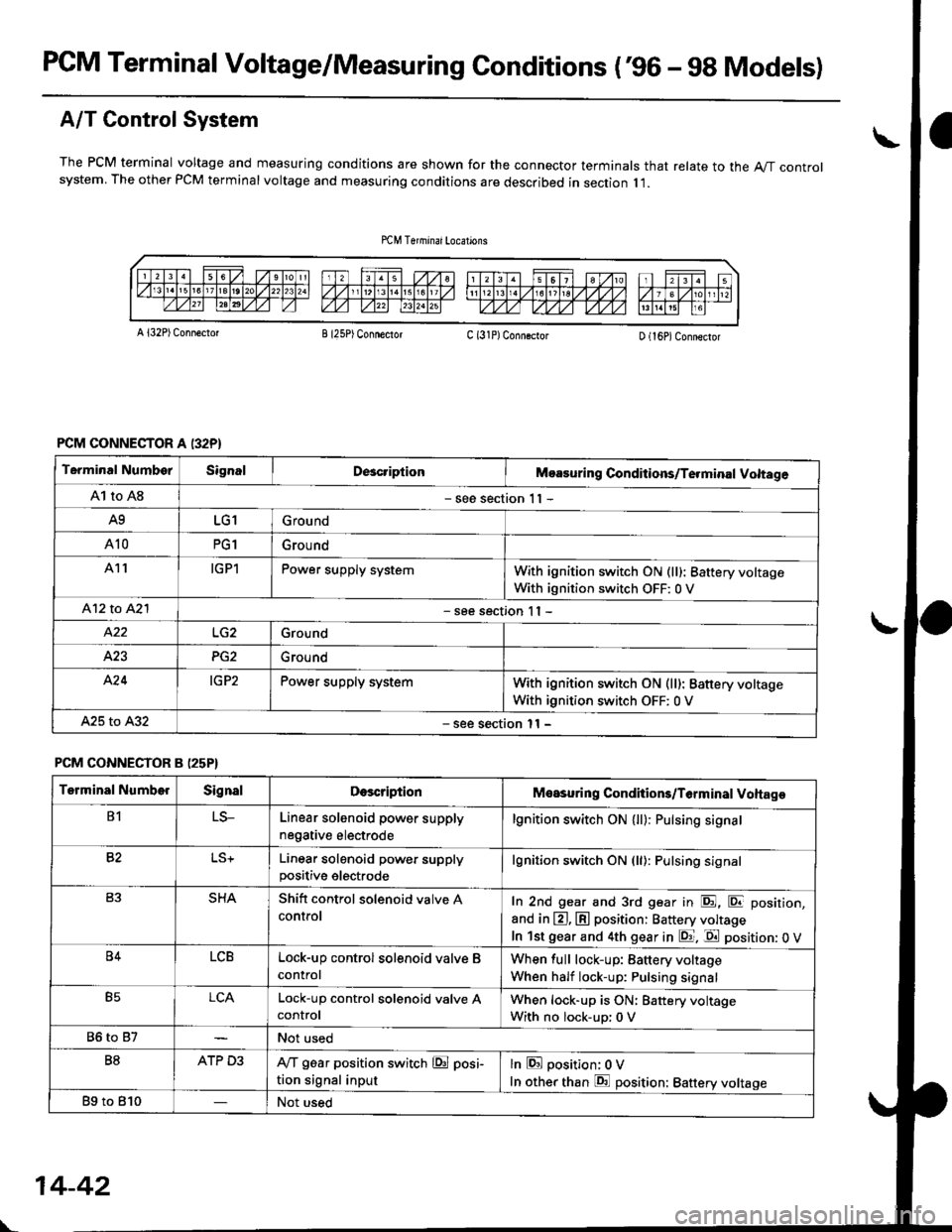
PCM Terminal Voltage/Measuring Gonditions ('96 - 9g Models)
A/T Control System
The PCM terminal voltage and measuring conditions are shown for the connector terminals that relate to the A"/T controlsystem. The other PCM terminal voltage and measuring conditions are described in section I l.
A l32P) Conn€ctotB I25P) ConnectorC (31P)ConngctorD (16P)Connector
PCM CONNECTOR A I32P}
Terminal NumborSignalDcacriptionMoasuring Conditions/Te.minal Voltage
A1 to A8- see section 1 I -
A9LG1Ground
A10PG1Grou nd
A11IGPlPower supply systemWith ignition switch ON (ll): 8attery voltage
With ignition switch OFF: 0 V
412 to A2l- see section I I -
Ground
423PG2Ground
A'24IG P2Power supply systemWith ignition switch ON (ll): Battery voltage
With ignition switch OFF: 0 V
A25 to A32- see section l1 -
PCM CONNECTOR B (25P}
Terminal NumberSignalDescriptionMeasuring Conditions/T6rminal Voltage
B1LS-Linear solenoid power supply
negative electrode
lgnition switch ON (ll): Pulsing signa.
82Linear solenoid power supplypositive electrode
lgnition switch ON (ll): Pulsing signal
SHAShitt control solenoid valve A
controlIn 2nd gear and 3rd gear in E, E position,
and in @, @ position: Battery voltage
In lst gear and 4th gear in E. E position: 0 V
B4LCBLock-up control solenoid valve B
control
When full lock-up: Battery voltage
When half lock-up: Pulsing signal
B5LCALock-up control sol€noid valve AcontrolWhen lock-up is ON: Battery voltage
With no lock-up: 0 V
86 to 87Not used
B8ATP D3IVT g6ar position switch @ posi-
tion signal input
lnEposition; OV
In other than E position: Battery voltage
Bg to 810Not used
\-
14-42
Page 721 of 2189

I
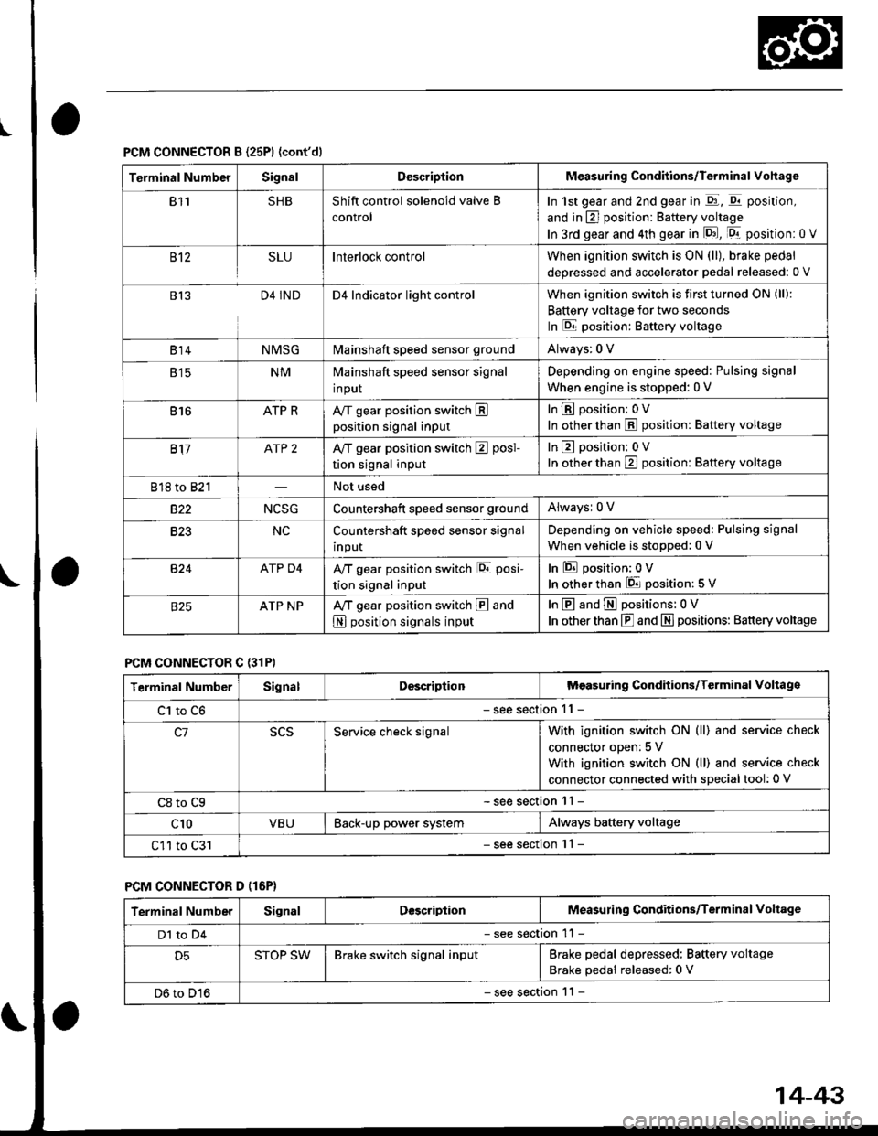
PCM CONNECTOR B {25P1 {cont'dl
Terminal NumberSignalDescriptionMeasuring Conditions/Terminal Vohage
811SHBShift control solenoid valve B
control
In 1st gear and 2nd gear in -q1, q11 position,
and in E] position: Battery voltage
In 3rd gear and 4th gear in lD.J, [Dr- position: 0 V
B't2SLUInterlock controlWhen ignition switch is ON (ll), brake pedal
deoressed and accelerator Dedal released: 0 V
813D4 INDD4 Indicator light controlWhen ignition switch is first turned ON (ll):
Battery voltage for two seconds
In E position: Baftery voltage
B't 4NMSGMainshaft speed sensor groundAlways: 0 V
E tcNMMainshaft speed sensor signal
input
Depending on engine speed: Pulsing signal
When engine is stopped: 0 V
816ATP RAy'T gear position switch Eposition signal input
InE position: 0V
In other than E position: Battery voltage
817ATP 2A/T gear position switch E posi-
tion signal input
InE position: 0V
In orher than E position: Battery voltage
818 to 821Not used
s22NCSGCountershatt speed sensor groundAlwaysr 0 V
B�23NCCountershaft speed sensor signal
input
Depending on vehicle speed: Pulsing signal
When vehicle is stopped: 0 V
B�24ATP D4Ay'T gear position switch lor posi-
tion signal input
InEposition:0V
In other than 6 position: 5 V
ATP NPA,/T gear position switch E and
N position signals input
InE and E positions: 0V
In otherthan E and N] positions: Battery voltage
PCM CONNECTOR C {31P)
Terminal NumberSignalDescriptionMeasuring Conditions/Terminal Voltage
Cl to C6- see section 11 -
c1Service check signalWith ignition switch ON (ll) and service check
connector oDen; 5 V
With ignition switch ON (ll) and service check
connector connected with sDecial tool: 0 V
C8 to Cg- see section 11 -
c10VBUBack-up power systemAlways battery voltage
C11 to C31- see section '11 -
PCM CONNECTOR D (16P}
Terminal NumberSignalDescriptionMeasuring Conditions/Terminal Voltage
Dl to D4- see section 11 -
D5STOP SWBrake switch signal inputBrake pedal depressed: Battery voltage
Brake pedal released: 0 V
D6 to D16- see section 1 l -
14-43
Page 725 of 2189

FCM CONNECTOR D {16P)
\o
14-47
Terminal NumberSignalDo3criptionMeasuring Conditions/Torminal Vohage
D1LCALock-up control solenoid valve A
control
When lock-up is ON: Battery voltage
With no lock-up: 0 V
SHBShift control solenoid valve B
control
In E position, in 1st and 2nd gear in E, E
position: Battery voltage
ln 3rd gear in E, E, in 4th gear in E posi-
tion;0 V
D3LCBLock-up control solenoid valve B
control
When full lock-up: Battery voltage
With half lock-up: Pulsing signal
D4Not used
D5VB SOLLock-up control solenoids, shift
control solenoids and linear
solenoid power supply electrode
with ignition switch oN (ll): Battery voltage
With ignition switch OFF: 0 V
D6ATP RAy'T gear position switch
E position input
tnEposition:0V
In other than E position: Approx. 10 V
SHAShift control solenoid valve A
control
In E] position, in 2nd and 3rd gear in p!, [Q]
position: Battery voltage
In 1st gear in E, @ position, in 4th gear in El
Dosition: 0 V
D8ATP D3A/T gear position switch
E position input
In E position:0V
In otherthan @ position: Approx. 10 V
D9ATP D4Ay'T gear position switch
E position switch
In El position: 0 V
In other than E position: Approx. 5 V
D10NCCountershaft speed sensor signal
input
Depending on vehicle speed: Pulsing signal
When vehicle is stooped: 0 V
D11NMMainshaft speed sensor signal
Inpur
Depending on engine speed: Pulsing signal
When engine is stopped: 0 V
D't2NMSGMainshaft speed sensor ground
D13ATP NPAy'T gear position switch E and
E position input
InE and E positions: 0V
In other than E and E positions: Approx. 10 V
D14AfP 2Ay'T gear position switch
E position input
tnEposition;0V
In other than E position: Approx. 10 V
D16NCSGCountershaft speed sensor
ground
Page 730 of 2189

Symptom-to-Component Ghart
Electrical System -'gG - 98 Models
*1: The DTC in the parentheses is the code E indicator light indicates when the Data Link connector is connected to theHonda PGM Tester.*2: Whenever the Honda PGM Tester or Scan Tool detects an automatic transmission control system DTC, p07OO will beset in the PGM-FI control svstem.
DTCIIE Indicaior
LightMILDotection ltemPage
P1753
fl)BlinksONLock-up control solenoid valve A14-56
P1758
\21BlinksONLock-up control solenoid valve B14-58
P1705
(51BlinksONAy'T gear position switch (short to groundl14-60
P1706
(6)OFFONA,/T gear position switch (open)14-62
P0753
l7lBlinksONShift control solenoid valve A14-64
P0758
{8)ElinksONShift control solenoid valve B14-66
POl20
(9)BlinksONCountershaft speed sensor14-68
P0715
{15)
'96 - 97
models:
OFF'98 model:
Blinks
ON
Mainshaft speed sensor
14-70
P1768
{16)BlinksONLinear solenoid't 4-72
P0740
(40)OFFONLock-up control system14-7 4
P0730
(41)OFFONShift control system14-75
P0700*,
(none)Automatic transmission control svstem in the pGM-Fl
control svstem
14-52
Page 732 of 2189

Symptom-to-Component Chart
Electrical System -'99 - 00 Models
*1: The DTc in the parentheses is the code E indicator tight indicates when the Data Link connector is connected to theHonda PGM Tester.*2: Whenever the Honda PGM Tester or scan Tool detects an automatic transmission control system DTc, p07oo will beset in the PGM-FI control svstem
DTC*IE Indicator
LightMILDotostion ltemPage
P1753
fi)BlinksONLock-up control solenoid valve A'14-80
P1758
t2lBlinksONLock-up control solenoid valve B14-82
P1705
{5}BlinksONAy'T gear position switch {short to ground)14-84
P1706
(6)OFFONy'VT gear position switch {open)14-81
P0753
\71BlinksONShift control solenoid valve A14-89
P0758
(8)BlinksONShift control solenoid valve B14-9r
P0720
(9)BlinksONCountershaft speed sensorr4-93
P0715
(15)B linksONMainshaft speed sensor14-95
P1768
(16)BlinksONLinear solenoid't 4-97
PO7 40(40)OFFONLock-up control system14-99
P0730
(41)OFFONShift control svstem14- 100
P0700*,
(none)OFFAutomatic transmission control system in the pGM_Fl
controt svstem
14-54
Page 738 of 2189

Electrical Troubleshooting ('96 - 9g Models)
Troubleshooting Flowchart - A/T Gear position Switch (Shortl
NOTE: Record allfreeze data before you troubleshoot.
Poiriblo Caus6
. Short in A/T go.. positionawhch wira. Fauhy A/T goa. position swhch
NOTE: Code P1705 (5)the PCM receives twoinputs at the same time.
is caused whengear position
' OBD ll Scln Toot indic.tes Cod6P1705.. Sofidi.gno3b E indicato] tighrblinksfivatim...
Observo th. A/T Go.r po3ition
Indicator:1. Turn the ignition switch ON l).2. Observe the A"/T gear positionindicator, and shitt to eachposttron,
Do any indicatoG stay onwhen the shift lever is not inthose positions?
Tho sy3tem b OK.t this timo.Check th6 wilc harnari for dam-rga.
M.r.ur. ATP R Vohlge:1. Shift to all positions otherthanE.2. Nileasure the voltage betweenthe 816 and Ag or A22 tormi-nats,
Check for short in tha wirobstwacn the 816 tcrminal and th6A/T go.r porition rwitch or A/Tg..r position indicltor. It wira i3OK, ch.ck for loo!€ FCfit connoc-to13. lf nacetaary, subrtitute aknown€ood Pcllt and roa|rsck.
ls there battery voltage?
Meesur. ATP NP Vohage:1. Shift to allpositions oth€r thanEorE.2. Moasure the voltage betweenthe 825 and A9 or A22 terminats.Check for short in the wireb.tw..n th6 B:I5 torminrt and th.A/T gclr poahion indicator. o. .short in tha wirrs between th.A/T gclr position indicator rndthe A/T gerr poiition switch. lfwir.3 r.o OK, chack tor loosoPCM conn.ctorr. It n.cosarry.sub.tituto a known-good pCM.nd r.chock.M.Gur. ATP D4 Voltago:1. Shift to allpositions otherthanlD.l.2. Measure the voltage betw€enrhe 824 and Ag or A22 termi-nals.
Check tor 3hort in tho wirobc{wocn the 824 terminrl and thoA/T ge.r poiition switch. lI wileia OK, chock tor loo3o plCM con-ncctoaa. It nacossarv, sublthute aknown-good PCM and rech€ck.
ls there approx. 5 V?
PCM CONNECTORS
Wire side of female terminals
YES
To page 14-6':
14-60