1996 HONDA CIVIC at gear position switch
[x] Cancel search: at gear position switchPage 447 of 2189

PGM-FI System
Barometric Pressure (BAROI Sensor
The scan tool indicates Diagnostic Trouble code (DTC) Pi106: A range/performance problem in the BaromerrrcPressure (BARO) Sensor circuit.
The scan tool indicates Diagnostic Trouble code (DTc) P1107: A low voltage probtem in the Baro sensor circurr.
The scan tool indicates Diagnostic Troubre code {DTC) p1108: A high vortage probrem in the Baro sensorcircuit.
fF1lot
tPlloal
The MIL ha3 been r€Dortsd on.DTC Pl106 is stored.
Problem verification:1. Do the ECM/PCM reset pro-cedure,2. Start the engine. Hold theengine at 3,000 rpm with noload (in Park or neutral) untilthe radiator fan comes on, thenlet it idle.3. Connect the SCS service connector.4. Test drive with the A/T in Eposition, M/T in 4th gear.5. Accelerate for five secondsusing wide open throttle.
Intormittont tailure, system is OKat this time.ls DTC P1106 indicated?
Substitut€ e known-good ECM/PCM and recheck. ll symptom/indication goes .way, .oplsce theo.iginal ECM/PCM.
The MIL has been .oported on.DTC P'l107 o. Pl108 is stored.
P.oblem veritication:1. Do the ECM/PClvl Reset pro
cedure,2. Turn the ignition switch ON (ll).
Intormittent frilure, syitem i3 OKat this time.ls DTC P1 107 or Pl108 indicated?
Substitute a known-good ECM/PCM and rechock. It symptom/indication goes away, .6placethe original ECM/PCM.
11-178
Page 460 of 2189

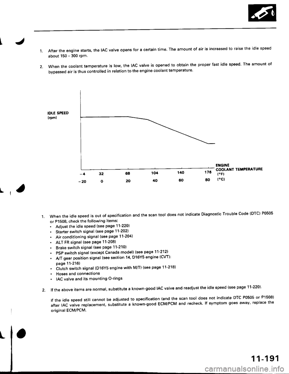
1.After the engine starts, the lAc valve opens for a certain time. The amount of air is increased to raise the idle speed
about 150 - 300 rpm.
When the coolant temperature is tow, the IAC valve is opened to obtain the proper fast idle speed. The amount of
bypassed air is thus controlled in relation to the engine coolant temperature'
IOLE SPEED
lrpml
176
80
ENGI ECOOLANI TEMPERATURE
t" Fl
toc)
ll
't.Whentheid|espeedisoutofspeciiicationandthescantoo|doesnotindicateDiagnosticTroub|ecode(DTc)P0505
or P1508. check the following items:
. Adiust the idle speed {see page 11-220}
. Starter switch signal (see page 11-202)
. Air conditioning signal (see page l1-204)
. ALT FR signal (see Page 11-2081
' Brake switch signal (see page 11-210)
. PSP switch signal (excapt Canada model) (see page 11-212)
. A,/T gear position signal {see section 14, Dl6Y5 engine (CVT):
page 11-216). Clutch switch signal (D16Y5 engine with M/T) (see page 11-218)
. Hoses and connections
' IAC valve and its mounting O-rings
lf the above items are normal, substitute a known-good IAC valve and readjust the idle speed (see page 11-220)
|ftheid|espeedsti||cannotbeadjustedtospecification(andthescantoo|doesnotindicateDTcP0505orP]50S)
after IAC valve replacement. substitute a known-good ECM/PCM and recheck. lf symptom goes away, replace the
original ECM/PCM.
Page 485 of 2189

ldle Control System
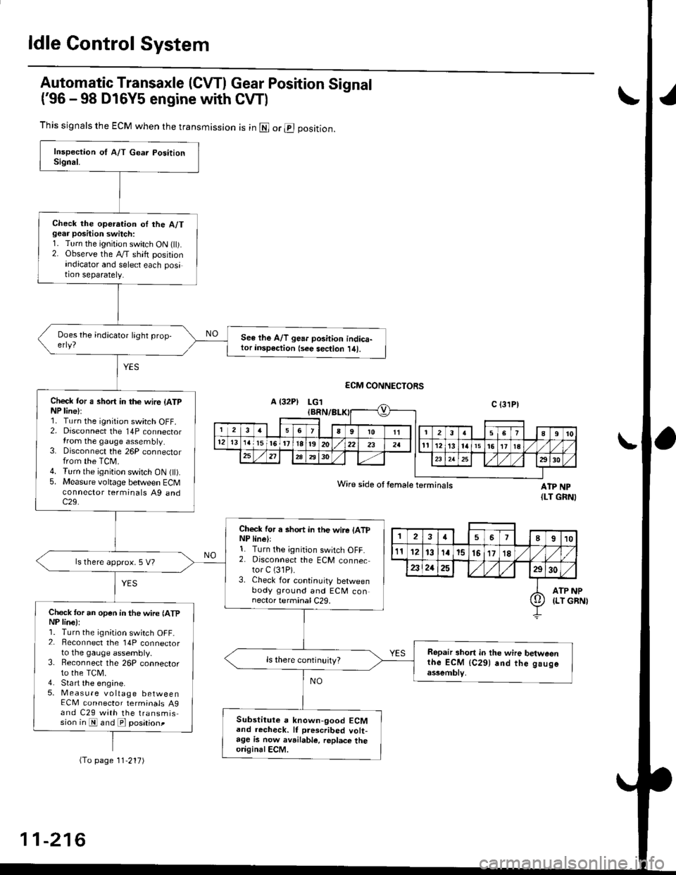
Automatic Transaxle (CVTI Gear Position Signal
('96 -98 D16Y5 engine with CW)
ATP NP{LT GRNI
INP
GBN)
This signals the ECM when the transmission is in @ or @ position.
Check the operation oI the A/Tgear position switch:1. Turn the ignition switch ON flt).2. Observe the A/T shift positionindicator and select each position separately.
See lhe A/T gear position indica-tor insp€ction {see sec{ion l/tl.
Check tor a short in the wir6 (ATpNP line):1. Turn the ignition switch OFF.2. Disconnect the 14P connectorIrom the gauge assembly.3. Disconnect the 26P connectorfrom the TCM.4. Turn the ignition switch ON fll).5. Measure voltage between ECMconnector terminals A9 andc29.
Check for a short in the wire lATpNP linell1. Turn the ignition switch OFF.2. Disconnect the ECM connector C (31P).
3. Check for continuity betweenbody ground and ECM connector terminal C29.
ls there approx. 5 V?
Check for an open in the wire lATpNP lina):1. Turn the ignition switch OFF_2. Beconnect the 14P connectorto the gauge assembly.3. Reconnect the 26P connectorto the TCM.4. Sta rt the engine.5. Measure voltage betweenECM connector terminals A9and C29 with the transmission in E and E posationt
Repair short in the wire betweenthe ECM {C291 and the gaugeassemblv,
Substitute a known-good ECMand recheck. lf prescribed volt-age is now avrilable, replace theo.iginalECM.
Wire side ot female terminals
2457I910
t112131a15151718
2321252930
ATP(LT io
(To page 11'217)
11-216
Page 486 of 2189

t
L
(From page 11-216)- Repair open in the wire
between the ECM {C291 and
lhe Ituge assomblv.- Repair open in the wire
betwoen the gauge assembly
and the A/T gea. Positionswitch.
ls there less than 1.0 V?
Chock for a short in the wite (ATP
NP line):Measure voltage between ECM
connector terminals Ag and C29
with the transmission in gear.
ReDair short in the wire be'tween
ECM (C291 and gauge a3somblY.ls there battery voltage?
A/T g€ar position signal is OK
LG1 IEBN/BLK)
ECM CONNECTORS
ATP NPWire side of female terminals (LT GRN)
Page 540 of 2189

\J
\
,96 D16Y5 engine,,96 D16r,gngino,,96 Dt6Y8 engine {3edan)' 37 D16Y5 engino..97 D16r, engine {coupe: KA, Kc mod-
els. sedan: KA, KC, KL {DX} models. hatchback: all modols}''97 Dl6Y8 ongine (s€dan: KA' KC mod€lsl:
The scan tool indicates Diagnostic Trouble code (DTC) P0441: Evaporative Emission (EVAP) control system
insufficient purge flow.
Description
By monitoring the purge line vacuum with the MAP sensor, the ECM/PCM can detect insufficient EVAP control system
purge flow.
Possible Cau3e
. EVAP Purge Control Solenoid Valve
. EVAP Purge Control Solenoid Valve Circuit
. EVAP Control Canister
. Vacuum Lines
. ECM/PCM
Troubl93hooting Flowchart
Wire side of femaleterminals
EVAP PURGE CONTROI-sottNotD vALvE 2P
CoNNECTOR (Cl1al
r-+-r
I'l'l
lG-ro.*l'rr"r
O)
Y
(cont'd)
11-271
- The MIL has bsGn.eportad on.- DTC milal k rtored.
Pioblem vsrificJtion:1. Start the engine. Hold the
engine at 3,000 rPm with no
load {in Park or noutral) until
the radiator fan comes on.
2. Do the ECM/PCM Reset Proce'
dure,3. Connect the SCS service con-
nector.4. Test-drive under following con-
ditions on the road- Without any electrical load- A/T in E or E Position(M/T in 3rd-sth gear)- Engine sPeed betweon
1,200 - 2.400 rpm.- Decelerate {rom 50 mph (80
knl/h)to 15 mph (24 km/h)lntormittont lailuro, sFtorn b OK
at thi. timo. Ch€ck tor Poor con'
ncction3 or looac wir.3 at C144
{EVAP purgo control tolonoid
vrtv.l .nd ECir/FCttl.
ls DTC P0441 indicatod?
Ch.ck fo. !n op€n in the wiro l|(illinel:1. Turn the ignition switch OFF.
2. Disconnect the EVAP Purgecontrol solenoid valve 2P con_
neclor,3. Turn the ignition switch ON (ll)
4. Measur€ voltage between bodyground and the EVAP Purgecontrol solenoid valve 2P con-
nector terminal No 1.
Rop.ir opor in tho wir6 b€two€n
the EVAP purgo codtiol tolonoid
v.lvo rnd tho No 15 ALIERNA'
TOR SP SENSOR 17.5 A)lu.o.
{To page 11-272)
Page 554 of 2189

\
\
(From page 11-284)
\(cont'd)
11-285
EVAP PURGE CONTROL SOI.INOID
VALVE 2P CONNECTOR IC114I
Wire side otfemaleterminals
?,
I,l,lil?"",,,u
EL,TWYEL)
Check the EVAP pirrge controlsolenoid valvei1. Disconnect the 2P connector
lrom the EVAP purge control
solenoid valve.
2. Ouickly raise the engine speed
to 3,000 rpm.
ls there vacuum?
InsDect vacuum ho56 routing.ll OK, replace the EVAP Purgecontrol solenoid valve.
Chock for a short in the wire(PCS linel:1. Turn the ignition switch OFF
2. Disconnect ECM/PCM connec'
tor A (32Pi.
3. Check for continuity between
the EVAP PUrge control sole
noid valve 2P connector termi
nal No.2 and body ground.
Check the vacuum when hot:
1. Turn the ignition switch OFF
2. Block the rear wheels and set
the parking brake.3. Jack up the front o{ the vehi-
cle and support it with safety
stands,4. Start the engine. Hold the
engine al 3,000 rpm wlth no
load (in Park or neutral) until
the radiator fan comes on, then
let it idle.5, Check for vacuum at the vac-
uum hose with transmissaonin gear (A/T in B Position,M/T in lst gear) after starting
the engrne.6. Ouickly raise the engine speed
to 3,000 rpm.
Reoair short in the wire botween
the EVAP purg€ cor|t]ol solenoid
valve and the ECM/pcM lA15l.ls there continuity?
Substitute a known-good ECM/
PCM and recheck. lf sYmPtom/indication goes eway. repl.c€ the
original ECM/PCM.
Check the EVAP Purg€ control
solenoid valve:1. Turn the ignition switch OFF
2. Disconnect the 2P connector
from the EVAP Purge control
solenoid valve and warm lt
up to normal operating tem_perature again if necessary
3. Stan the engine.4. At the harness side, measure
voltage between the EVAP
Purge control solenoid valve
2P connector terminal No. 1
and No. 2 with the transmission in gear (A,/T in E Posi-tion, M/T in 1st gear).
In3pect vacuum ho3€ touting.
ll OK, replace EVAP Purge con-
lrol aolenoid vtlv€.
Check lo. an open in the wire
llGl linel:At the harness side, measure volt
age between the EVAP Purge con-
trol solenoid valve 2P connectorterminal No. 1 and body groundRepeir open in tho wire between
EVAP purge conttol solenoid valv€
and the No. 15 ALTERNATOR SP
SENSOR (7.5 A fu3e
IBLK/YELI
lTo page 11 286i(To page 11-286)
Page 559 of 2189

Emission Control System
Ch€ck the EVAP purge controlsolenoid valv6:1. Disconnect the 2P connectorfrom the EVAP purge controlsolenoid valve.2. Ouickly raise the engine speedto 3,000 rpm.
Insped vacuum hose routing.lf OK. roplace the EVAP purge
control solonoid valve.
Chock tor r short in the wir€
{PCS line):1. Turn the ignition switch OFF.2. Disconnect ECM/PCM connec-tor A (32P).
3- Check tor continuity betweenthe EVAP purge control sole-noid valve 2P connector termi-nal No. 2 and body ground.
Check the vacuum when hot:1. Turn the ignition switch OFF.2. Block the rear wheels and setthe parking brake.3. Jack up the lront of the vehi-cle and support it with safetystands.4. Start the engine. Hold theengine at 3,000 rpm with noload (in Park or neutrali until
the radiator fan comes on, thenlet it idle.5. Check for vacuum at the vac-uum hose with transmissionin gear (A/T in E position,
lvl/T in 1st gear) after startingthe engine.6. Ouickly raise the engine speedto 3,000 rpm.
Rooair shoft in the wire belwegnthe EVAP pulg6 control solenoidvalvs and tho ECM/PCM {A61.ls there continuity?
Substitute a known-good ECM/PCM and rech6ck. lt 3ymptom/indicrtion 90e3 rway, r6plac6 th€o.iginal ECM/FCM.
Check th€ EVAP purge controlsolenoid valve:1. Turn the;gnition switch OFF.2. Disconnect the 2P connectorfrom the EVAP purge controlsolenoid valve and warm itup to normal operating tem-perature again if necessary.3. Start the engine.4- At the harness side, measurevoltage between the EVAPpurge control solenoid valve2P connector terminal No. 1and No.2 with the transmis-sion in gear {A/T in E posi-tion, M/T in lst geari.
In3pect vacuum hoae routing.lf OK, repl.ce EVAP purge con-trol solonoid valve.ls there battery voltage?
Chock for an open in the wire(lG1 lina):At the harnoss side, measure volt-age beNveen the EVAP purge con-trol solenoid valve 2P connectorterminal No. 1 and body ground.
Repair open in the wire b€lwe€nEVAP purge contrl 3olenoid valv6and lhe No. 15 ALTERNATOR SPSENSOR 17.5 A, fu3e.
ls there battery voltage?
Evaporative Emission (EVAPI Controls (cont'dl
(From page 11-289)
(To page 11-291)
11-290
IJ
EVAP PURGE CONTROL SOLENOIDVALVE 2P CONNECTOR IC114I
PCS
IRED/YEL)
temaletermrnars
of
PCS(RED/YEL)
tGlIBLK/YEL)
{To page 11 291)
Page 682 of 2189

Description
(cont'dl
Gear Selection
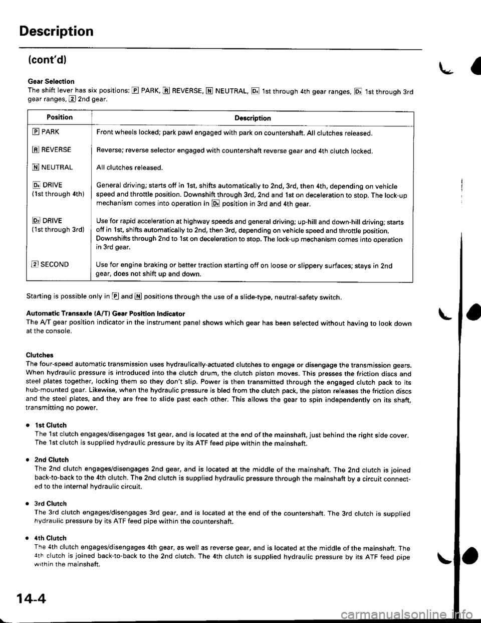
The shift lever has six positions: E PARK. E REVERSE, N NEUTRAL, E 1st through 4th gear ranges, E 1st through 3rdgear ranges, @ 2nd gear.
Starting is possible only in E and E positions through the use of a slide-type, neutral-safety switch.
Automatic Transaxle (A/f, Gear Position Indicator
The Ay'T gear position indicator in the instrument panel shows which gear has been selected without having to look downat the console.
Clutch€s
The four-speed automatic transmission uses hydraulically-actuated clutches to engage or disengage the transmission gears.When hydraulic pressure is introduced into the clutch drum, the clutch piston moves. This presses the friction discs andsteel plates together, locking them so they don't slip. Power is then transmitted through the engaged clutch pack to itshub-mounted gear. Likewise, when the hydraulic pressure is bled from the clutch pack, the piston releases the friction discsand the steel plates, and they are free to slide past each other. This allows the gear to spin independently on its shaft,transmitting no power.
lst Clutch
The 1st clutch engages/disengages 1st gear, and is located at the end of the mainshaft, just behind the right sroe cover.The 1st clutch is supplied hydraulic pressure by its ATF feed pipe within the mainshaft.
2nd Clulch
The 2nd clutch engagegdisengages 2nd gear, and is located at the middle of the mainshaft. The 2nd clutch is joined
back-to-back to the 4th clutch. The 2nd clutch is supplied hydraulic pressure through the mainshaft by a circutr connect-ed to the internal hvdraulic circuit,
3rd Clutch
The 3rd clutch engages/disengages 3rd gear, and is located at the end of the countershaft. The 3rd clutch is suooliedhydraulic pressure by its ATF feed pipe within the countershaft.
ilth Clutch
The 4th clutch engages/disengages 4th gear, as well as reverse gear, and is located at the middle of the mainshaft. The4th clutch is joined back-to-back to the 2nd clutch. The 4th clutch is supplied hydraulic pressure by its ATF feed pipewith in the mainshaft.
\-a
PositionDe3cription
E PARK
E REVERSE
N NEUTRAL
E DRIVE
{1st through 4th)
Ei DRtvE('lst through 3rd)
B SECOND
Front wheels locked; park pawl engaged with pa* on countershaft. All clutches released.
Reverse; reverse selector engaged with countershaft reverse gear and 4th clutch locked.
All clutches released.
General driving; starts off in 1st, shifts automatically to 2nd, 3rd, then 4th, depending on vehiclespeed and throttle position. Downshift through 3rd, 2nd and 1st on deceleration to stop. The lock-upmechanism comes into operation in @ position in 3rd and 4th gear.
Use for rapid acceleration at highway speeds and general driving; up-hill and down,hill dfiving; stansotf in 1st, shifts automatically to 2nd, then 3rd, depending on vehicle speed and throttle position.
Downshifts through 2nd to lst on deceleration to stop. The lock-up mechanism comes into operationin 3rd gear,
Use for engine braking or better traction starting off on loose or slippery surfaces; stays in 2ndgear, does not shift up and down.
14-4