1996 HONDA CIVIC 7P connector
[x] Cancel search: 7P connectorPage 1457 of 2189
Clutch InsPection
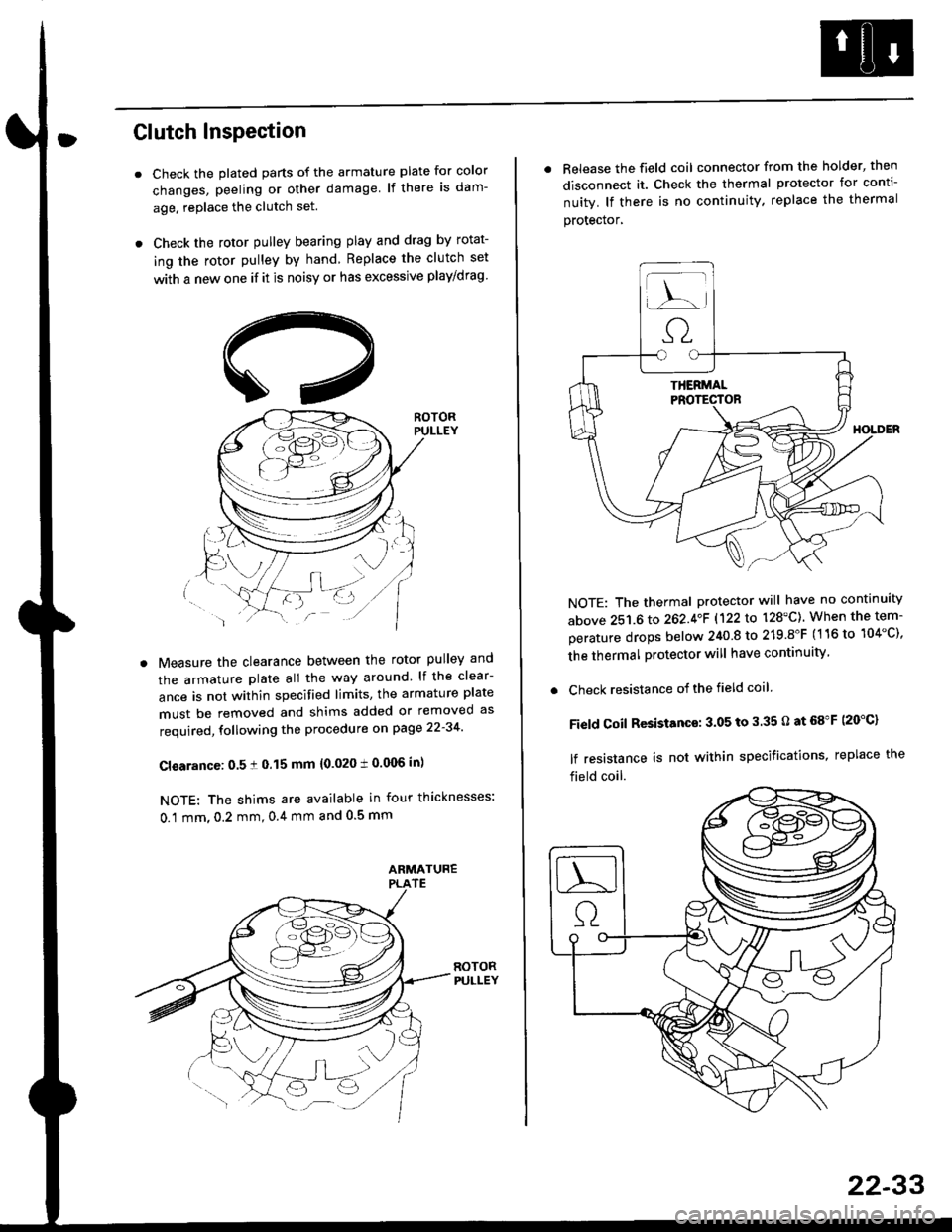
Check the plated parts of the armature plate for color
changes, peeling or other damage lf there is dam-
age. replace the clutch set.
Check the rotor pulley bearing play and drag by rotat-
ing the rotor pulley by hand Replace the clutch set
with a new one if it is noisy or has excessive play/drag
Measure the clearance between the rotor pulley and
the armature plate all the way around lf the clear-
ance is not within specified limits, the armature plate
must be removed and shims added or removed as
required, following the procedure on page 22-34
Cl€arance: 0.5 ! 0.15 mm {0.020 t 0.006 in)
NOTE: The shims are available in four thicknesses:
0.1 mm,0.2 mm,0.4 mm and 0.5 mm
. Release the field coil connector from the holder' then
disconnect it. Check the thermal protector for conti-
nuity. lf there is no continuity. replace the thermal
protecror,
NOTE: The thermal protector will have no continuity
above 251.6 to 262.4oF 1122lo 128'C). When the tem-
perature drops below 240 8 to 219.8"F (116 to 104"C),
the thermal protector will have continuity
. Check resistance of the field coil
Field Coil Resistance: 3.05 to 3.35 O at 68"F (20"C)
lf resistance is not within specifications, replace the
field coil.
22-33
Page 1459 of 2189
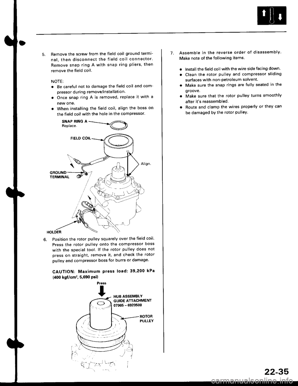
5. Remove the screw from the field coil ground termi-
nal, then disconnect the field coil connector.
Remove snap ring A with snap ring pliers, then
remove the field coil
NOTE:
. Be careful not to damage the field coil and com-
pressor during remove/installation.
. Once snap ring A is removed, replace it with a
new one.
. When installing the field coil, align the boss on
the field coil with the hole in the compressor.
SNAP RING AReplace.
Position the rotor pulley squarely over the field coil.
Press the rotor pulley onto the compressor boss
with the special tool. lf the rotor pulley does not
press on straight, remove it, and check the rotor
pulley and compressor boss for burrs or damage.
CAUTION: Maximum press load: 39,200 kPa
(,[00 kgf/cm'�, 5,590 Psi)
Press
THUB ASSEMBLYGUIDE ATTACHMENT07965 - 6920500
ROTORPULLEY
t'l
i,'
7. Assemble in the reverse order of disassembly
Make note of the following items.
. lnstall the field coil with the wire side facing down.
. Clean the rotor pulley and compressor sliding
surfaces with non-petroleum solvent.
. Make sure the snap rings are fully seated in the
groove.
. Make sure that the rotor pulley turns smoothly
after it's reassembled
. Route and clamp the wires properly or they can
be damaged bY the rotor Pulley.
22-35
Page 1460 of 2189
Compressor (SANDENI
Thermal Protestor Replacement
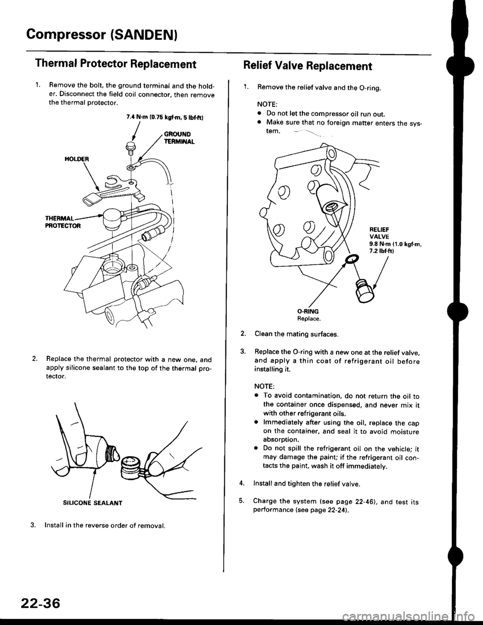
1. Remove the bolt, the ground terminal and the hold-er. Disconnect the field coil connector. then removethe thermal Drotector.
7.{ N.m 10.75 ksf.m,5lbtfr)
/
SILICONE SEALANT
3. Install in the reverse order of removal.
GROUNDIERMINAL
HOI.I'ER
PNOTECTOR
Replace the thermal protector with a new one. andapply silicone sealant to the top of the thermal pro-
tector.
22-36
oo
Relief Valve Replacement
'1.Remove the relief valve and the O-ring.
NOTE:
. Do not let the compressor oil runout.. Make sure that no foreign matter enters the sys-tem,
RELIEFVALVE9.8 N.m {1.0 kgl.m,7.2 tbl.lrl
O.RINGReplace.
Clean the mating surfaces.
Replace the O-ring with a new one at the relief valve.and apply a thin coat of refrigerant oil beforeinstalling it.
NOTE:
. To avoid contamination. do not return the oil tothe container once dispensed, and never mix it
with other refrigerant oils.o lmmediately after using the oil, replace the capon the container, and seal it to avoid moistureabsorption.
. Do not spill the refrigerant oil on the vehicle; itmay damage the paint; if the refrigerant oil con-tacts the paint, wash it off immediately.
Install and tighten the relief valve.
Charge the system {see page 22-461, and test itsperformance 1se6 page 22-241.
Page 1461 of 2189
Compressor (DENSO)
Replacement
1.lf the compressor is marginally operable, run the
engine at idle speed, and let the air conditioning work
for a few minutes, then shut the engine off
Disconnect the negative cable from the battery'
Recover the refrigerant with a recovery/recycling/
charging station lsee page 22-271
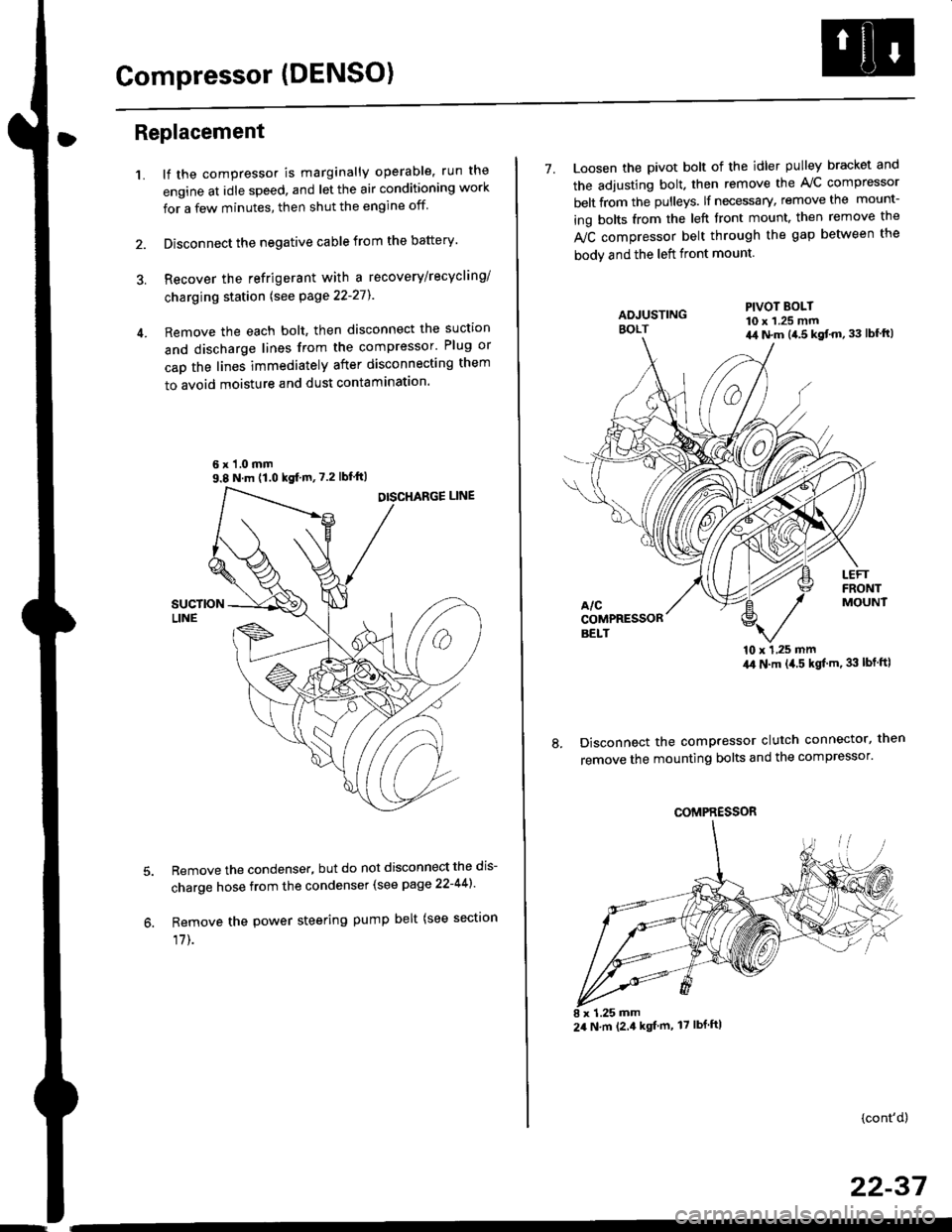
Remove the each bolt, then disconnect the suction
and discharge lines from the compressor' Plug or
cap the lines immediately after disconnecting them
to avoid moisture and dust contaminatlon.
6 x '1.0 mm9.8 N.m (1.0 kgf m,7.2 lbfft)
Remove the condenser, but do not disconnect the dis-
charge hose from the condenser (see page 22-441'
Remove the power steering pump belt (see sectron
17]-.
7. Loosen the pivot bolt of the idler pulley bracket and
the adjusting bolt. then remove the A,/C compressor
belt from the pulleys. lf necessary, remove the mount-
ing bolts from the left front mount. then remove the
fuC compressor belt through the gap between the
bodv and the left front mount.
'10 x 1,25 mm4,0 N.m (,1.5 kgf'm. 33 lbt ftl
Disconnect the compressor clutch connector, then
remove the mounting bolts and the compressor'
PIVOT BOLT10 x 1.25 mm4,1 N.m (4.5 kgt'm,33 lbfft)
COMPRESSOR
24 N.m (2.4 kgf m, 17 lbf ftl
(cont'd)
22-37
Page 1468 of 2189
Condenser
Replacement
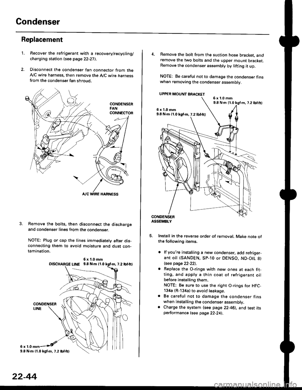
1.Recover the refrigerant with a recovery/recycling/
charging station lsee page 22-271.
Disconnect the condenser fan connector from theAy'C wire harness, then remove the A,/C wire harnessfrom the condenser fan shroud.
Remove the bolts, then disconnect the dischargeand condenser lines from the condenser.
NOTE: Plug or cap the lines immediately after dis-connecting them to avoid moisture and dust con-tamination,
6r1.0
6x1.0mmolscHARGE L|NE 9.8 N.m 11.0
9.8 N.m 11.0 kgl.m, 7.2 lbf.ftl
22-44
4. Remove the bolt from the suction hose bracket, andremove the two bolts and the upper mount bracket.Remove the condenser assembly by lifting it up.
NOTE: Be careful not to damage the condenser finswhen removing the condenser assembly.
UPPER MOUNT BRACKET
5. Install in the reverse order of removal. Make note ofthe following items.
. lf you're installing a new condenser, add refriger-ant oil (SANDEN, SP-10 or DENSO, ND-O|L 8)
\see page 22-22l.-
. Replace the O-rings with new ones at each fit-ting, and apply a thin coat of refrigerant oilbefo.e installing them.
NOTE; Be sure to use the right O-rings for HFC,134a (R-134a) to avoid leakage.o Be careful not to damage the condenser finswhen installing the condenser assembly.. Charge the system (see page 22-46), and test itsperformance (see page 22-24i.
6x1.0mm9,8 N.m 11.0 kg{.m, 7.2lbtft}
6x1.0mm9.8 N.m 11.0 kst m, 7.2 lbf.ftl
Page 1471 of 2189

l'f .
Electrical
Special Toofs .,....................,23-2
Troubleshooting
Tips and Precautions ..............,.................... . 23-3
Five-step Troubleshooting .............. ......... . . 23-5
wire color codes ..........,23-5
Schematic Symbols ........,................... . . .. .... 23-6
Relay and Control Unit Locations
Engine Compartment ...,..................... ... .. . 23'7
Dashboard ......................23-8
Dashboard/Door ......... 23-12*Airbags ................. ....... Section 24
Air Conditioning ......... Section 21
Aftelnator ..........."""" """ 23-112
Anti-lock Brake System {ABS) Section 19*A/T Gear Position Indicator .....................,. .... ... 23-149
Automatic Transmission Svstem .... . ....... Section 14
Batterv ......... . . . ... ...... .......23-91
Blower controls .. . ... Section 2l
Charging System ....'...........23'112
Connector ldentilication and Wire Harness
Routing .................. ......23'13
Cruise Control ............,........23-240
Dash Lights Brightness Controller ............. ....... 23-180
Fan controfs "" 23'126
Fuel PumD ........ . ........ section 11
Fuses/Refay ...............,..,,.. 23'62
PGM-FI Control System ......................,....... Section 1 1
*Gauges
Circuit Diagram ....,.,.......23-131
Fuef Gauge ...........'.'.......23-142
Gauge/lndicator .. . .. 23-129
Ground Distribution .. . 23-75
Heatei controls .. . ..... Section 21*Horn................. ...............23-196
*tgnition Switch ....................23-89
lgnition System .......,.... 23-102
*lntegrated Control Unit ....................................... 23-156
fnterlock System ,........ . . , ,23-144
Lighting System . . . .. ......... 23-161
Lights, Exterior
Back-up Lights ..'............23'171
Brake Lights .................. 23'174
Daytime Bunning Lights (Canadal ............... 23'166
Front Parking Lights ......,................ .'. .......... 23-167
Front Turn Signal Lights .......... . . ............ ..,.23-167
Headtights ....".'....-... ..... 23'167
High Mount Brake Light ...................... ... .23'179
License Plate Lights ...... 23'176
Taitfights ................ .......23'171
lnterior Lights ..-.......,, . 23-142
Moonroof ..,.................,........ 23-235
Power Distribution ....... . . .23-61
Power Door Locks .......,,,. .23'251
Power Mirrors ,..............,.,...23'206
Power Relays ....... . ...... . . .. 23-86
Power Windows ............,,....23-220
Rear Window Defogger .......................... . . ... . . 23-2OO
Spark Plugs . ..... . ........ .....23-111
Slarting System ................23-93*stereo Sound Svstem ,................. ..... ... . ... ,.,.,,23'147'Supplemental Restraint System (SRS) ... . Section 24
Turn Signal/Hazard Flasher System .......'.'....-... 23-173
*Undel-dash Fuse/Relay Box ............,.................. 23-85
vehicfe soeed sensor (VSSI """" ""' 23-140+Wipers/Washers .........,.,.,...23-214
NOTE: Unless otherwise specified, references to auto-
matic transmission (Mf) in this section include the CVT.
Page 1472 of 2189
Special Tools
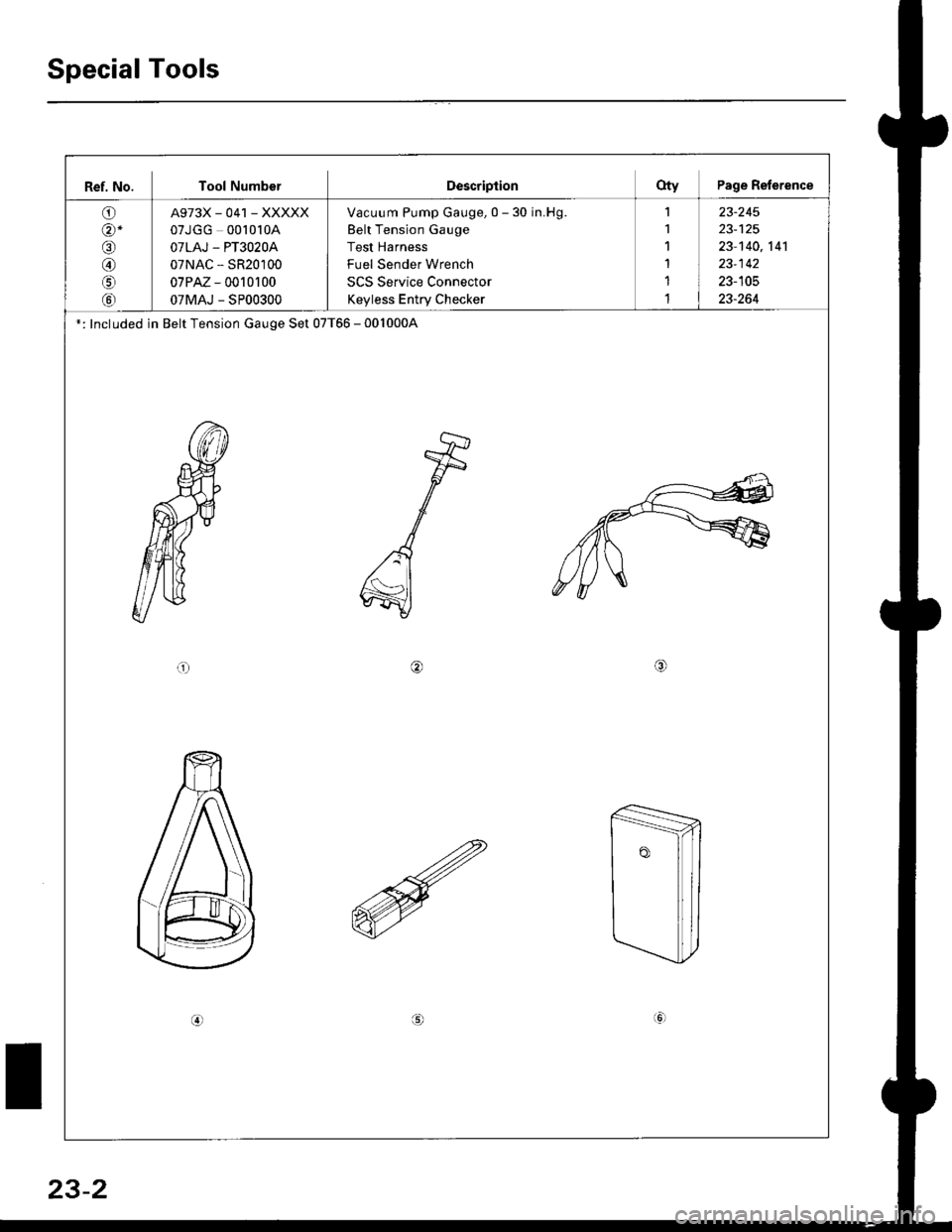
Ref. No. Tool NumberDescriptionOty Page Reference
O)
@-
o
@
o
tol
A973X_041 _XXXXX
07JGG 00l0l0A
OTLAJ - PT3O2OA
07NAC - SR20100
07PM - 0010r 00
07MAJ - SP00300
Vacuum Pump Gauge, 0 - 30 in.Hg.
Belt Tension Gauge
Test Harness
Fuel Sender Wrench
SCS Service Connector
Keyless Entry Checker
1
1'I
1
1
1
23-245
23-140,141
23-142
23-105
23-264
': Included in Belt Tension Gauge Set 07T66 - 0010004
or/4,
(!
23-2
Page 1473 of 2189
Troubleshooting
ll.
Tips and Precautions
Bef ore Troubleshooting
. Check applicable fuses in the appropriate fuse/relay
box.
. Check the battery for damage, state of charge, and
clean and tight connections.
. Check the alternator belt tension.
CAUTION:
. Do not quick-charge a battery unless the battery
ground cable has been disconneqted, otherwise you
will damage the alternator diodes.
. Do not attempt to crank the engine with the battery
ground cable loosely connecled or you will severely
damage the wiling,
Handling Connectois
. Make sure the connectors are clean and have no loose
wire terminals.
. Make sure multiple cavity connectors are packed with
grease (except watertight connectors)
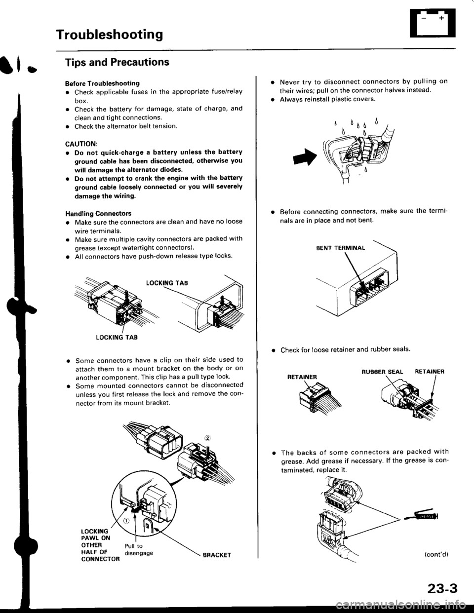
. All connectors have push-down release type locks.
Some connectors have a clip on their side used to
attach them to a mount bracket on the body or on
another component. This clip has a pulltype lock.
Some mounted connectors cannot be disconnected
unless you first release the lock and remove the con-
nector from its mount bracket.
LOCKINGPAWL ONOTHERHALF OFCONNECTOR
Pull todrsengage
LOCKING TAB
BRACKET
Never try to disconnect connectors by pulling on
their wires; pull on the connector halves instead
Alwavs reinstall plastic covers.
Before connectang connectors,
nals are in place and not bent.
make sure the terml-
. Check for loose retainer and rubber seals.
RETAINER
The backs of some connectors are packed with
grease. Add grease if necessary. lf the grease is con-
taminated, replace it.
(cont'd)
23-3