Page 1405 of 2189
Blower Motor
BLOWER MOTOR 2P CONNECTOR
Wire side of lemale terminals
JUMPERWIRE
(cont'd)
21-31
Blower motor does not run at all.
Check the No. 55 (40 A) Iuse in
the under-hood fuse/relay box,
and the No. 17 (7.5 A){use in the
undeFdash fuse/relay box.
Boplace th€ fuse(3), and rechock.
Check th€ blow€r motor Powelsupply circuit:1. Disconnect the blower motor
2P connector.2. Turn the ignition switch ON {ll).
3, Measure the voltage between
the No. 1 terminal oI the blow
er motor 2P connector and
body ground.
ls there battery voltage?
Check tha blower motor:
1. Turn the ignition switch OFF
2. Reconnect the blower motor
2P connector.3. Connect the No.2 terminal o{
the blower motor 2P connector to bodv ground with a
tumper wire.4. Turn the ignition switch ON {ll}
Does the blower motor run?
fo page 21-32
To page 21-33
Page 1407 of 2189
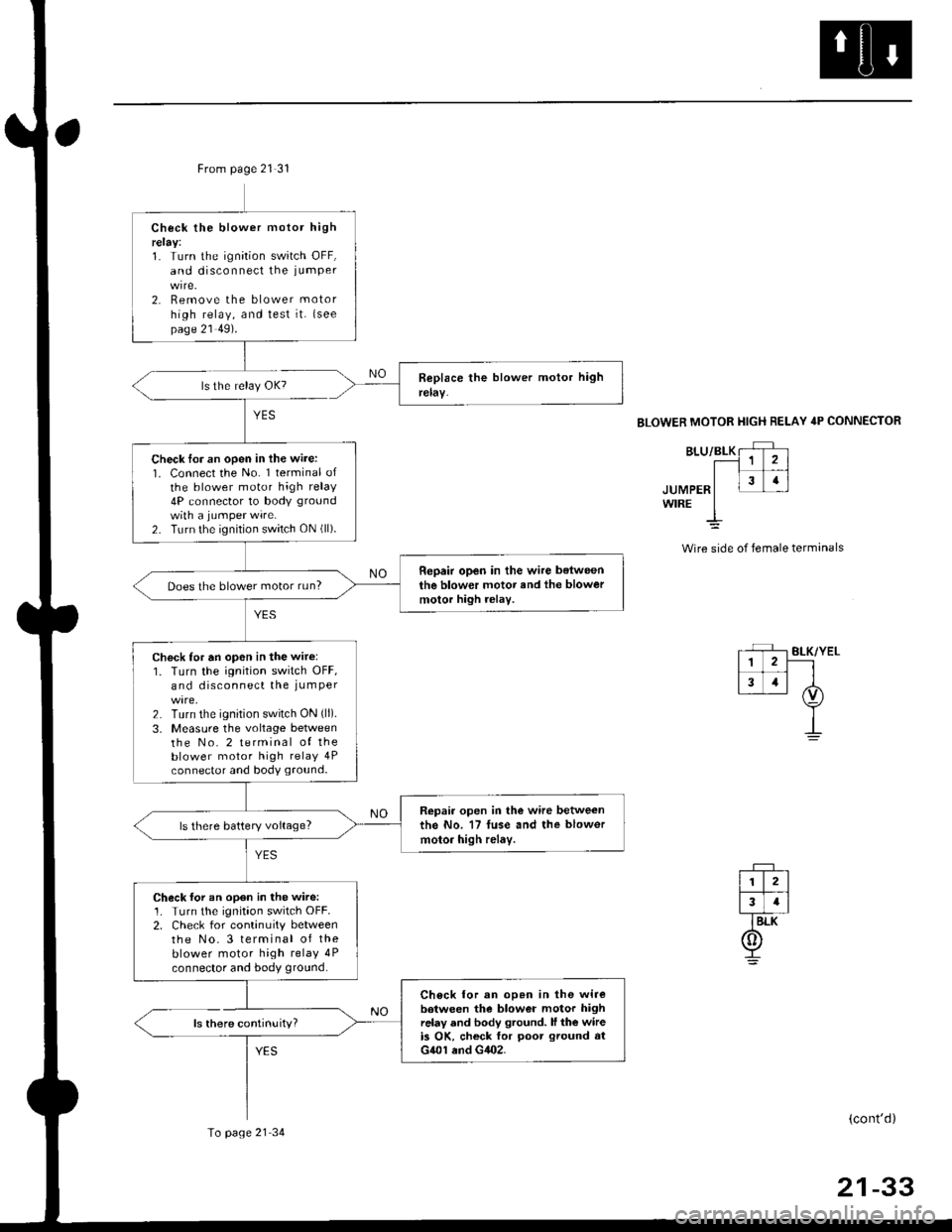
From page 21 31
ls there continuity?
YES
Check the blower motor highrelay:1. Turn the ignition switch OFF,and disconnect the iumPer
2. Remove the blower motor
high relay, and test it. {seepage 21 49).
Check lor an open in the wire:1. Connect the No. 1 terminal ofthe blower motor high relay4P connector to body ground
with a jumPer wire.2. Turn the ignition switch ON (ll).
Repair open in the wire belweenthe blower motor and the blowermotor high rolay.Does the blower motor run?
Check for an op6n in the wir6:1. Turn the ignition switch OFF,and disconnect the iumPer
2. Turn the ignition switch ON (ll).
3, Measure the voltage betweenthe No. 2 terminal of theblower motor high relay 4Pconnector and body ground.
Repair open in the wire betweenthe No. 17 fuse and the blowor
motor high relay.ls there battery voltage?
Check for an open in the wire:1. Turn the ignitaon switch OFF.2. Check for continuity betweenthe No.3 terminal of theblower motor high relay 4P
connector and body ground.
Ch6ck lor an op.n in the wirebotween the blower motor highrelay and body ground. ll the wireis OK, ch6ck for poot ground atG401 end G402.
To page 21 34
BLOWER MOTOR HIGH RELAY 4P CONNECTOR
JUMPERWIRE
Wire side of female terminals
(cont'd)
21-33
Page 1408 of 2189
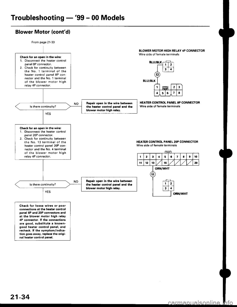
Troubleshooting -'99 - 00 Models
Blower Motor {cont'dl
BLOWER MOTOR HIGH RELAY 4P CONNECTORWire side of female terminals
BLU/BLK
BLU/ALK
HEATER OONTROL PANEL 8P CONNECTORwir€ sido ot f€male torminals
HEATER CONTROL PANCL 2OP CONNECTORWire side of female terminals
From page 21-33
Check tor an opgn in the wiro:1. Disconnect the heater controlpanel 8P connector.2. Check lor continuity betweenthe No. 1 terminal of theheater control panel 8P con-nector and the No. 1 terminalot the blower motor highrelay 4P connector.
Repsi. op€n in the wir. betw.enthe h..t.r contrcl p.ncl .nd thoblowar motor high rahy.
Ch€ck for an opon in the wir6:1. Disconnect the heater controlpanel 20P connector.2. Check for continuity betweenthe No. 13 terminal of theheater control panel 20P con-nector and the No. 4 terminalof the blower motor highrelay 4P connector.
Ropair opon in tho wiro botwoontha hartor cor rol pangl rnd thablower motor high .elay.
Ch.ck for looso wiros or poor
conn€dions at th6 heato. controlpanel 8P and 20P connectoB andat the blowol motor high relty4P connoctor. It tho connoctionsare good, substitute a known-good heatcr control panel, andrecheck. It the symptom/indica-tion goos away, rgplaco the oiigi-nal heater control oanol.
2
34
o
t2
a568
I23a5078I10
11121315,/1,/1,/m
ORN/WHT
o
12
34
OBN/WHT
21-34
Page 1409 of 2189
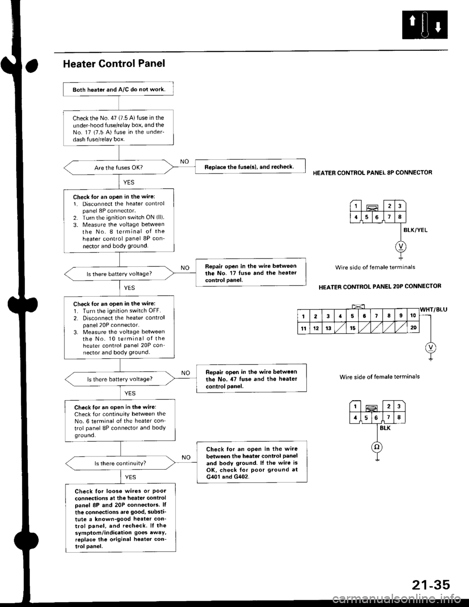
Both heater and A/C do nol work.
checkthe No.47 (7.5 A)fuse in the
under-hood fuse/relay box, and theNo. 17 {7.5 A) fuse in the under-
dash fuse/relay box.
ReDlace the tuse{s), and recheck.
Check lor an open in the wire:
1. Disconnect the heater controlpanel 8P connector,2. Turn the ignition switch ON (ll).
3. Measure the voltage between
the No. I terminal of the
heater control panel 8P con-
nector and body ground.
Repair open in the wire betweenthe No. '17 luse and th6 heatercontrol oanel,ls there battery voltage?
Check for an open in the wire:
1. Turn the ignition switch OFF.
2. Disconnect the heater controlpanel20P connector.3. Measure the voltage lletweenthe No. 10 terminal of theheater control Panel 20P con-nector and body ground.
Repair op6n in the wir€ between
the No. il7 tuse and the heater
controloanel,ls there battery voltage?
Check for an open in the wite:Check for continuity between theNo. 6 terminal of the heater con
trol panel 8P connector and bodyground.
Ch6ck tor an open in lhe wire
betwoen the heator control Paneland bodv ground. lf the wire isOK, check for poor ground atG401 and G402.
ls there continuity?
Check for looso wires or Poolconneciions at the heater controloanel 8P and 20P connectors. lf
the connections are good, substi'
tute a known-good heat€r con-trol Danel, and recheck. lI thesymptom/indication goes awaY,r6place the original h€ater con-troloanel.
HEATER CONTROL PANEL 8P CONNECTOR
BLK/YEL
Wire side of female terminals
HEATER CONTROL PANEL 2OP CONNECTOR
Wire side of temale terminals
I2
1578
BLK
o
1
4I
v
Page 1410 of 2189
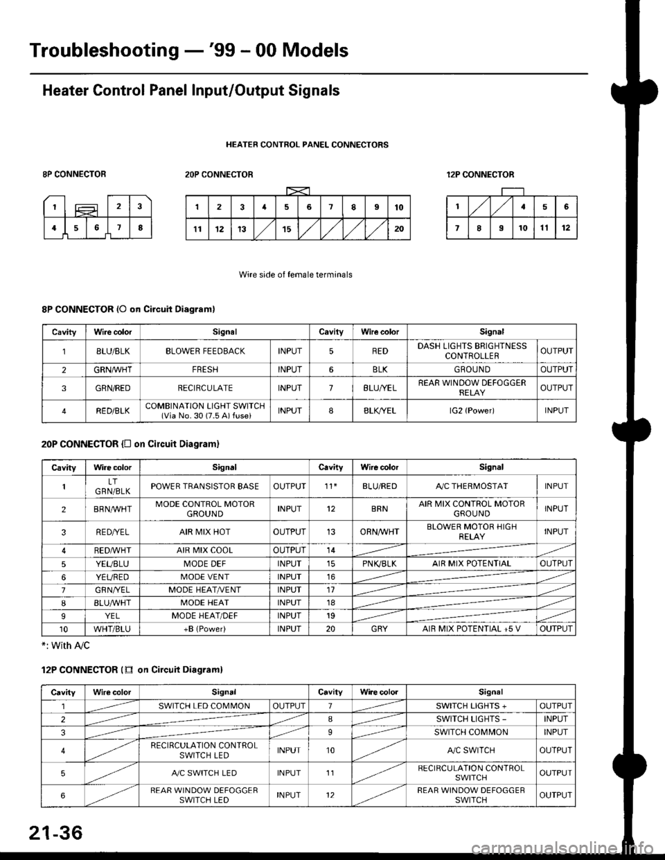
Troubleshooting -'99 - 00 Models
Heater Control Panel Input/Output Signals
HEATER CONTROL PANEL CONNECTORS
8P CONNECTOR2OP CONNECTOR12P CONNECTOR
Wire side of female terminals
8P CONNECTOR (O qn Circuit Diagram)
20P CONNECTOR {D on circuit Diagram}
*: with Ay'c
12P CONNECTOR (tr on Circuit Diagraml
CavityWire colorSignalCavilyWhe colorSignal
BLU/8LKBLOWER FEEDBACKINPUT5REDDASH LIGHTS BRIGHTNESSCONTROLLEROUTPUT
2GRN/lVHTFRESHINPUT6BLKGBOU N DOUTPUT
3GRN/REDRECIRCULATEINPUT7BLU/YELREAR WINDOW DEFOGGERRELAYOUTPUT
4RED/BLKCOMBINATION LIGHT SWITCH(Via No. 30 (7.5 A) fuse)INPUT88LfiELlG2 {Power)INPUT
CavityWire colorSignalCavityWire colorSignal
LTGRN/BLKPOWER TRANSISTOR EASEOUTPUT't1BLU/REDAy'C THERMOSTATINPUT
2BRNMHTMODE CONTROL MOTORGROUNDINPUT12BRNAIR MIX CONTROL MOTORGROU NDINPUT
3RE D/YELAIR MIX HOTOUTPUT13ORNAA/HTBLOWER MOTOR HIGHRELAYINPUT
RED,ryvHIAIR MIX COOLOUTPUT14
5YEUBLUMODE DEFINPUTPN K,/BLKAIR MIX POTENTIALOUTPUT
6YEUREDMODE VENTINPUT16
7GRNI/ELMODE HEAT/r'ENTINPUT11
IBLUAVHTMODE HEATINPUT18
9YELMODE HEAT/DEFINPUT19
10WHT/BLU+B (Power)INPUT20GRYAIR MIX POTENTIAL +5 VOUTPUT
CavityWilecolorSignalCavityWi.e cololSignal
lSWITCH LED COMMONOUTPUT1SWITCH LIGHTS +OUTPUT
2ISWITCH LIGHTS -INPUT
39SWITCH COMMONINPUT
4RECIRCULATION CONTROLSWITCH LEDINPUT10A,/C SWITCHOUTPUT
5A./C SWITCH LEDINPUT11RECIRCULATION CONTROLSWITCHOUTPUT
6REAR WINDOW DEFOGGERSWITCH LEDINPUT12REAR WINDOW DEFOGGEBSWITCHOUTPUT
21-36
Page 1411 of 2189
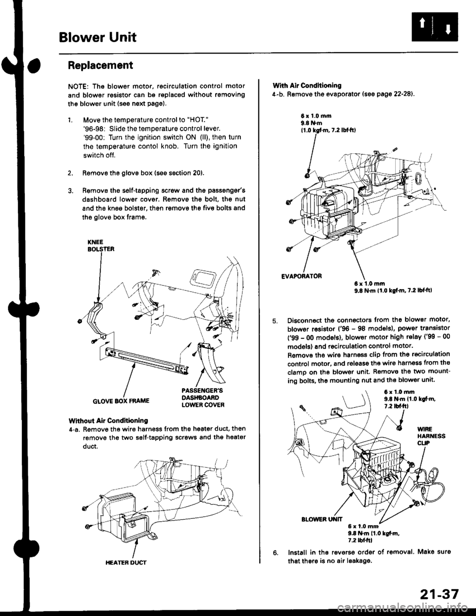
Blower Unit
Replacement
NOTE: The blower motor, recirculation control motor
and blower resistor can bs replacsd without rsmoving
th€ blower unit (see neld Page).
1. Move the temperature control to "HOT."
'96-98: Slide the temperature control lever.'99-00: Turn the ignition switch ON (ll), then turn
the temperature contol knob. Turn the ignition
switch off,
Remove the glovs box (ses ssction 20),
R€move ths s6lf-tapping screw and ths passsng6r's
dashboard low€r cover. Removo the bolt, the nut
and the kn€e bolst€r, then remove the fiv€ bolts and
the glove box trame,
Without Air Condhioning
4-a. Remove the wiro harness from the h68t€r duct, then
remove the two self-tapping scrsws and the heatsr
duct.
KNEE
GLOVE BOX FRAME
HEATER DUCT
21-37
Wrth Air Conditioning
4-b. Removo th6 ev8porator (sss pago 22-28).
6x1.0m|n9.8 N'm
6x1.0mm9.8 N'm lt'o tgf'm, t.2 lb{'ttl
Disconnoct the connectors trom th€ blower motor,
blowor r6sistor {'96 - 98 models), power transiator
('99 - 0O modsls), blowor motor high telay ('99 - 00
models) and recirculation control motor.
R€mov€ ths wiro harnoss clip from tho recirculation
control motor, and release the wir6 harnsss from ths
clamo on the blowor unit. Remove the two mount-
ing bolts, tho mounting nut and ths blowor unit'
9.8 .m 11.0 tgfm,1.2 tblfrl
lnstall in ths reverso order of removal. Mako surs
that thsre is no air leaka96.
6x1.0mm9,t N'm 11.0lgi.m,7.2 tbf.fil
Page 1414 of 2189
Heater Unit
Replacement (cont'dl
6.
7.
8.
9.
Remove the dashboard (see section 20).
Remove the heater duct (see page 21-37) or evapo-
rator (see page 22-28).
Disconnect the connectors from the mode control
motor and air mix control motor ('99 - 00 models),
then remove the wire harness clips and wire har-
ness from the heater unit. Remove the clip from the
heater duct, then remove the two mounting nuts
and the heater unit.
6x1.0mm9.8 N.m 11.0 kgl.m,7.2 lbf.ftl
HEATER UNIT
lnstall in the reverse order of removal. Make note of
the following items.
Apply sealant to the grommets.
Do not interchange the inlet and outlet heater
hoses. Make sure that the clamps are secure.
Refill the cooling system with engine coolant
(see section 10).
Connect all cables, and make sure they are prop-
erly adjusted (see page 21-44 (96 - 98 models)
or page 21-45 ('99 - 00 models)).
Make sure that there is no air leakage.
21-40
Page 1416 of 2189
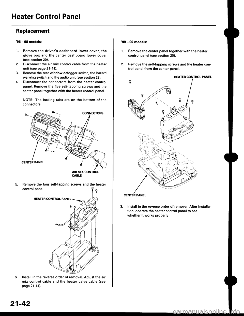
Heater Control Panel
'95 - 98 modolsi
Remove the driver's dashboard lower cover, the
glove box and the center dashboard lower cover(see section 20).
Disconnect the air mix control cabls from the heater
unit {see page 21-44).
Remove the rear window defogger switch, the hazard
warning switch and the audio unit (see section 23).
Disconnect the connectors from the heater control
panel. Remove the five self-tapping screws and the
center panel together with the heater control panel.
NOTE: The locking tabs are on the bottom of the
connecrors.
Install in the .everse order of removal. Adjust the air
mix control cable and the heater valve cable {seepage 21-44)..
Replacement
1.
Remove the four self-tapping screws and the heater
21-42
1.
'9!, - 00 modols:
Remove the center panel together with the heater
control panel (see section 20).
Remove the self-tapping screws and the heater con-
trol panelfrom the center Danel.
Install in the reverse order of removal. After
tion, operate the heater control panel to see
whether it works properly.
installa-