Page 1298 of 2189

Dashboard
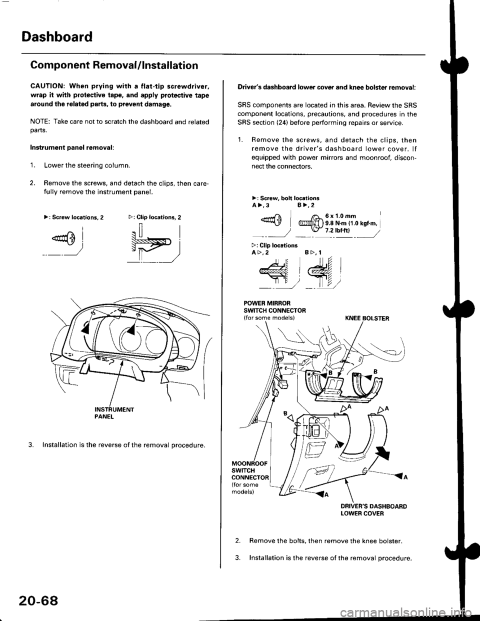
Component RemovaUlnstallation
CAUTION: When prying with a flat-tip screwdriver,
wrap it with protoctivo tape, and apply protective tape
around tho r6lat6d parts, to prevent damag6.
NOTE: Take care not to scratch the dashboard and relatedpans.
Instrument Danel removal:
1.Lower the steering column.
Remove the screws, and detach the clips, then care-
fully remove the instrument panel.
3. Installation is the reverse of the removal procedure.
>: Clip locations, 2
.il |
Pit)_ _ ,/
>: Screw locations,2
^l
@sl
:)
PANEL
20-68
Driver's dashboard lower cover and knee bolster removal:
SRS components are located in this area. Review the SRS
component locations, precautions. and procedures in the
SRS section (24) before performing repairs or service.
'1. Remove the screws, and detach the clips, then
remove the driver's dashboard lower cover. lf
equipped with power mirrors and moonroof, discon-
nect the connectors.
>: Screw, boh loc.tionsA>.3B>,2
_-rri I /a_6x1.0mm*\Y @{[) s 8 N'm tt o rst'm,
_-_- J _ \J- 7 2_rbtftl -_
>: Clip locationsA>.2 B >, 1
tu
DRIVER'S DASHBOARDLOWER COVER
Remove the bolts, then remove the knee bolster.
Installation is the reverse of the removal procedure.
Page 1299 of 2189
Glove box removal:
Remove the bolts, then remove the glove box.
>: Bolt locations,2
Installation is the reverse of the removal proceoure
Side air vent/Side defogger trim removal:
SIOE DEFOGGER TRIMSHOPTOWET_Carefully PrY rt at the
then remove it,side edge,
SIDE AIR VENTRemove the driver's dashboard lower
cover, or oPen the glove Dox,
HOOKS
then push the cliPs from each
opening by hand, and Pull it
out. Disconnect the connedors(driver's side).
HOOKS
DASH LIGHTSBRIGHTNESSCONTROLLERCONNECTOR{for some models)
CFUISE CONTROLMASTER SWITCHCONNECTOR(for some models)
Center dashboard lower covel:
1. Remove:
. Driver's dashboard lower cover
. Glove box
2. Remove the screws and bolt, then remove the cen-
ter dashboard lower cover. Disconnect the accesso-
ry socket connector'
>i Boh, screw locations
a>, 1 B>'5
A s*o.e-- I A
@;*;ry'-1'-.J _e)
3. Installation is the reverse of the removal proceoure'
(cont'd)
20-69
LOWER COVER
Page 1300 of 2189

Dashboard
Gomponent Removal/lnstallation
(cont'd)
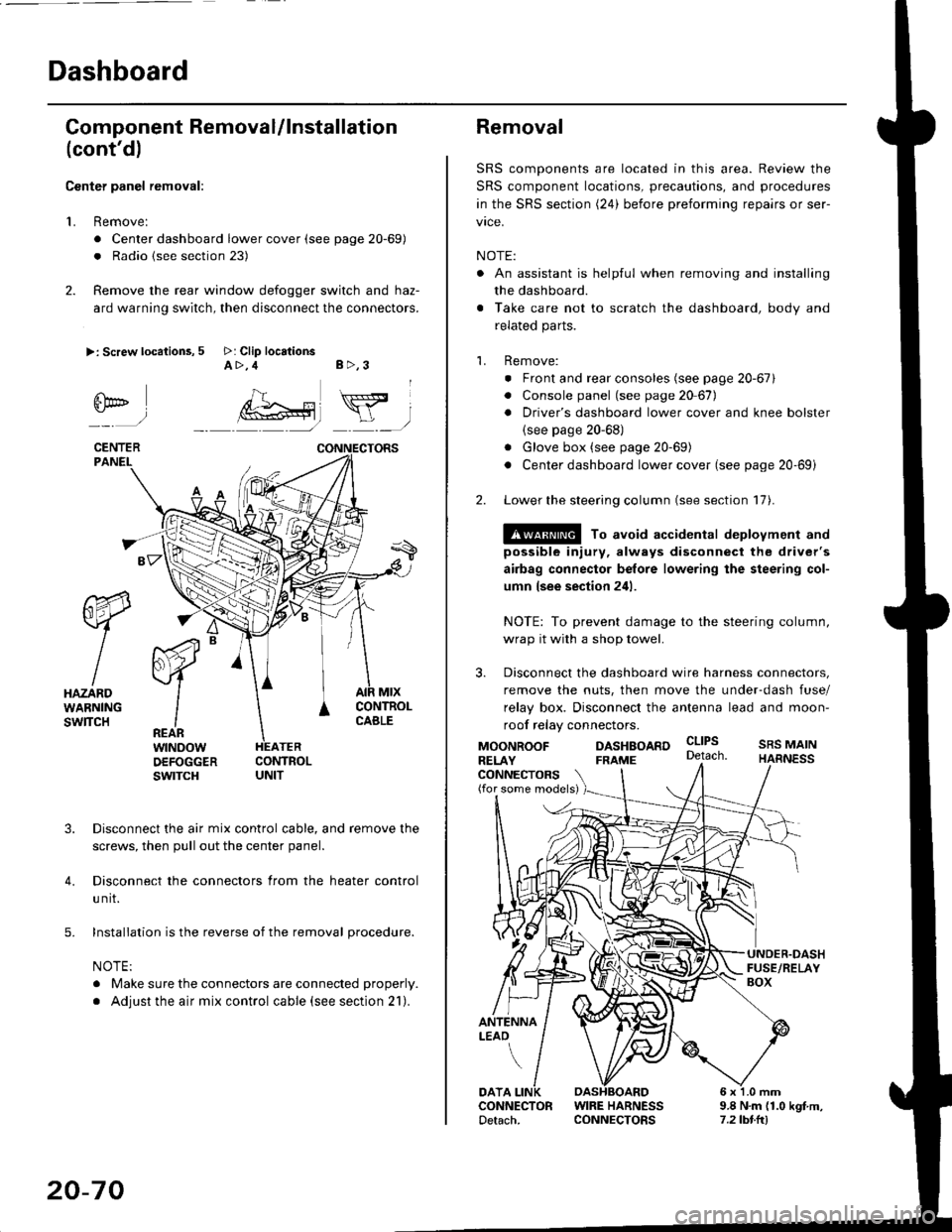
Center panel removal:
1. Remove:
. Center dashboard lower cover (see page 20-69)
. Radio {see section 23)
2. Remove the rear window defogger switch and haz-
ard warning switch, then disconnect the connectors.
>: Screw locations, 5 >: Clip locationsA>,4 B>,3
fii*-)
CENTERPANEI.
rt-xR.
W
IHAZARDWARNINGswlTcH
r44 "
F.IZvl
IIREARwtNoowOEFOGGERswtrcH
MtxCONTNOLCABLE
3. Disconnect the air mix control cable, and remove the
screws, then pull out the center panel.
4. Disconnect the connectors from the heater control
u nit.
5. Installation is the reverse of the removal procedure.
NOTE:
. Make sure the connectors are connected properly.
. Adjust the air mix control cable (see section 21).
20-70
Removal
SRS components are located in this area. Review the
SRS component locations, precautions, and procedures
in the SRS section (24) before preforming repairs or ser-
vice.
NOTE:
. An assistant is helpful when removing and installing
the dashboard.
. Take care not to scratch the dashboard, body and
related parts.
1. Remove:
o Front and rear consoles (see page 20-67)
. Console panel (see page 2O 67),
. Driver's dashboard lower cover and knee bolster(see page 20-68)
. Glove box (see page 20-69)
. Center dashboard lower cover (see page 20-69i
2. Lower the steering column (see section 17).
@ To avoid accidental deplovment and
possible injury, always disconnect the driver's
airbag connector belore lowering the steering col-
umn lsee section 241.
NOTE: To prevent damage to the steering column,
wrap it with a shop towel.
3. Disconnect the dashboard wire harness connectors,
remove the nuts, then move the under-dash fuse/
relay box. Disconnect the antenna lead and moon-
roof relay connectors.
DASHBOARD cltPs
CONNECTORS(for some models)
MOONROOFRELAY
ANTENNALEAO
FRAME
SRS MAINHARNESS
9.8 N.m (1.0 kgf m,7.2lbt.ltl
DATACONNECTOR WIRE HARNESSDetach. CONNECTORS
Page 1301 of 2189
Remove the following parts Irom the dashboard'
. Driver's dashboard side cover
o Passenger's dashboard lower cover
. Dashboard center lid
Disconnect the connectors and air mix control cable'
6x1.0mm9.8 N.m 11.0 kgl.m,
D>, 1
@7 2'orftl - ---//_._J
,{nil Lll , ,"o
Ift#5 L //Hl Wlj%u|5 i//Wt qT
W72-t11 7'::--J
>: Clip locationsA>, 1 B>, 1
Loosen the bolt.
DASHBOARD
AIR MIX CONTROL
CONNECTORS
FRONT PASSENGER'SAIRBAG CONNECTOR
Remove the bolts, then lift and remove the dashboard'
CAUTION: Use proteqtive plates on the bottom ot the front pillar trim'(cont'd)
20-71
M,::;:"lx3T:iJnif:3lilH:fl"*:1::f"*'il;ili"'"
disconnect rhe front passeneer's airbas
>: Bolt, screw locaiions
A>,7B>, 1
,i( 8x125mm(!,@ 22 N.m t2.2 kstm,-v, 16 tbf.ftl
8xl.25mm I22 N.m 12.2 kgt'm, I'"tt:___J
c>, 1
@
c>,6
Page 1302 of 2189
Dashboard
Removal (cont'd)
7. lf necessary, remove the dashboard frame from the dashboard.
>: Screw localionsa>,21 B>,4a: Nut locations, 3
>: Clip locations
l^1./'\
I Shl:' Olb'tvY/l\-]1
ra 6 x '1.0 mm
Yi.!i[11"-"'".
DASHBOARD BRACKETSIDE COVER
Installation is the reverse of the removal orocedure.
NOTE:
. Before tightening the bolts, make sure the dashboard wire harnesses are not pinched.a Make sure the connectors, antenna lead and air mix control cable are connected properly.
FRONT PASSENGER'S
OASHBOARD
20-72
Page 1304 of 2189
Front Seat
Removal
CAUTION: When prying with a flat-tip screwdriver, wrapit with protective tape lo prevent damage.
NOTE: Take care not to scratch the seat covers and body.
1. Remove the seat track end cover, then remove thebolts.
SEAT TRACKCOVER
FRONT SEAT
)
SEAT TRACKEND COVER
BOLT8 x'1.25 mft22 N..n 12.2 kgl.m,16 rbf.ft)
8 x 1.25 mm22 N.rn 12,2 kgl.m,16 tbtft)
20-74
2. Lift the driver's front seat, then disconnect the seatbelt switch connector.
SEAT BELTswtTcHCONNECTOR
4.
Remove the headrest.
Carefully remove the front seat through the dooropening.
Installation is the reverse ol the removal procedure.
NOTE: Make sure the connector is connected prop-
erry.
5.
Page 1307 of 2189
Harness Wiring and Recline
Cable Locations
NOTE: When installing the seat cushion, make sure the
seat belt switch harness, connector and recline cable are
fastened correctly on the seat cushion frame'
Driver's:>: Clip locations
Passenger's (with lecline cablel:
TRACK
Seat Cover RePlacement
CAUTION: Put on gloves to protest yout hands'
NOTE: Take care not to tear the seams or damage the
seat covers.
Seat-back cover removal:
1. Release the hook, and fold back the seat-back cover'
Release all inside springs, then fold back the seat-
back cover.
Remove the headrest.
Remove the headrest guide, then remove the seat-
back cover.
lnst;llation is the reverse of the removal procedure'
NOTE: To prevent wrinkles when installing a seat-
back cover, make sure the material is stretched evenly
over the pad before securing the inside springs and
hook.
3.
(cont'd)
20-77
HEADREST
Page 1317 of 2189

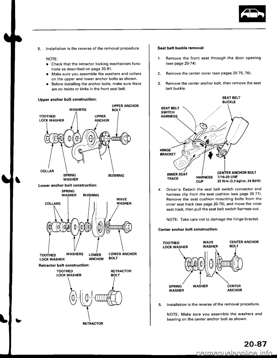
5. Installation is the reverse of the removal procedure.
NOTE:
. Check that the retractor locking mechanism func-
tions as described on page 20-91.
. Make sure you assemble the washers and collars
on the uoDer and lower anchor bolts as shown.
. Before installing the anchor bolts, make sure there
are no twists or kinks in the front seat belt.
SPRINGWASHER
Lower anchor bolt construction:
SPRINGWASHER BUSHING
BUSHING
COLLARS
LOCKWASHER ANCHOR
Reiractor bolt construction:
TOOTHEOLOCK WASHER
WASHERS LowERLOWER ANCHORBOLT
RETRACTOB
Seat belt buckle removal:
1. Remove the front seat through the door opening
{see page 20-74).
2. Remove the center cover (see pages 20-75,76).
3. Remove the center anchor bolt, then remove the seat
belt buckle.
SEAT BELTBUCKLE
ANCHOR BOLTINNER SEATTRACK
TOOTHEOLOCK WASHER
SPRINGWASHER
HARNESS 7/16.20 UNF
CLIP 32 N m (3.3 kgt m, 24 lbf'ft)
4. Driver's: Detach the seat belt switch connector and
harness clip from the seat cushion (see page 20 77).
Remove the seat cushion mounting bolts from the
inner seat track {see page 20-75), and move the inner
seat track, then pull the seat belt switch harness out.
NOTE: Take care not to damage the hinge bracket.
Centsr anchor bolt construction:
CENTER ANCHORBOLT
WASHER
Installation is the reverse of the removal procedure.
NOTE: Make sure you assemble the washers and
bearing on the center anchor bolt as shown.
20-47